EP1070786B1 - Fahrweg für eine Magnetschwebebahn mit Langstator-Linearantrieb sowie Bausatz und Verfahren zu seiner Herstellung - Google Patents
Fahrweg für eine Magnetschwebebahn mit Langstator-Linearantrieb sowie Bausatz und Verfahren zu seiner Herstellung Download PDFInfo
- Publication number
- EP1070786B1 EP1070786B1 EP00115723A EP00115723A EP1070786B1 EP 1070786 B1 EP1070786 B1 EP 1070786B1 EP 00115723 A EP00115723 A EP 00115723A EP 00115723 A EP00115723 A EP 00115723A EP 1070786 B1 EP1070786 B1 EP 1070786B1
- Authority
- EP
- European Patent Office
- Prior art keywords
- stator
- packs
- tooth
- length
- sections
- Prior art date
- Legal status (The legal status is an assumption and is not a legal conclusion. Google has not performed a legal analysis and makes no representation as to the accuracy of the status listed.)
- Expired - Lifetime
Links
- 238000000034 method Methods 0.000 title claims description 16
- 238000010276 construction Methods 0.000 title claims description 9
- 238000004519 manufacturing process Methods 0.000 claims abstract description 11
- 238000005339 levitation Methods 0.000 claims abstract description 9
- 239000000463 material Substances 0.000 claims description 27
- 239000011248 coating agent Substances 0.000 claims description 6
- 238000000576 coating method Methods 0.000 claims description 6
- 238000004904 shortening Methods 0.000 claims description 5
- 230000015572 biosynthetic process Effects 0.000 claims 1
- 238000006073 displacement reaction Methods 0.000 claims 1
- 239000000969 carrier Substances 0.000 description 37
- 239000011295 pitch Substances 0.000 description 28
- 230000007797 corrosion Effects 0.000 description 3
- 238000005260 corrosion Methods 0.000 description 3
- 238000007667 floating Methods 0.000 description 3
- 238000012216 screening Methods 0.000 description 3
- 238000004804 winding Methods 0.000 description 3
- 229910000831 Steel Inorganic materials 0.000 description 2
- 230000006735 deficit Effects 0.000 description 2
- 238000009826 distribution Methods 0.000 description 2
- 239000010410 layer Substances 0.000 description 2
- 230000000737 periodic effect Effects 0.000 description 2
- 239000010959 steel Substances 0.000 description 2
- 239000002131 composite material Substances 0.000 description 1
- 230000001419 dependent effect Effects 0.000 description 1
- 238000005516 engineering process Methods 0.000 description 1
- 230000005284 excitation Effects 0.000 description 1
- 230000002349 favourable effect Effects 0.000 description 1
- 238000009434 installation Methods 0.000 description 1
- 238000003475 lamination Methods 0.000 description 1
- 235000013490 limbo Nutrition 0.000 description 1
- 239000011241 protective layer Substances 0.000 description 1
- 238000003860 storage Methods 0.000 description 1
- 230000001360 synchronised effect Effects 0.000 description 1
- 230000007704 transition Effects 0.000 description 1
Images



Classifications
-
- E—FIXED CONSTRUCTIONS
- E01—CONSTRUCTION OF ROADS, RAILWAYS, OR BRIDGES
- E01B—PERMANENT WAY; PERMANENT-WAY TOOLS; MACHINES FOR MAKING RAILWAYS OF ALL KINDS
- E01B25/00—Tracks for special kinds of railways
- E01B25/30—Tracks for magnetic suspension or levitation vehicles
- E01B25/32—Stators, guide rails or slide rails
Definitions
- the invention relates to a track specified in the preamble of claim 1 Genus and a kit and a method according to the preamble of claim 15 and 16, respectively for its production.
- the driveways can be made with concrete or steel girders as well as supports on demand or to be built near the ground.
- the girders in the direction of one before are arranged in series, all for the operation of the maglev train required equipment. This is especially true for the Guide the vehicles of a maglev required side guide rails as well for the reaction rails required for carrying and driving in the form of stator packets, their functional surfaces exactly on given by the routing space curves must lie.
- the equipment consists of in particular the stator packs, of linear components running within Curved track sections the respective space curve in the manner of a polygon approach.
- the resulting deviations from the ideal lines are extreme low, since the radii of curvature of the routes for reasons of vehicle construction is not may be less than about 350 m.
- stator packs are a Magnetic levitation train with long-stator linear drive, usually also on its underside, alternately provided with teeth and grooves, in which a single- or multi-phase AC traveling wave winding is inserted (DE 196 20 221 A1), which is used to generate the for the drive of the maglev railway required traveling field is used. That's it customary to provide identical linear drives on both sides of the vehicles and therefore to equip each lane of a driveway with two parallel stators. This creates two separate but mechanically fixed drive systems.
- Statorween same length is for design and cost reasons advantageous, but also brings disadvantages. These consist e.g. in that different sized column the ideal distribution of the magnetic field of the long stator to disturb. Since the individual stator packs are comparatively short (e.g., 1000 mm to 2000 mm), this leads to rapid periodic changes in the forces when driving over, with which the vehicles are kept in limbo, and as a result of it Parts of the track or vehicle may be excited to vibrate. These Vibrations can not only the life of all elements of the infrastructure and the Vehicles, but also the ride comfort and the sound generation unfavorably influence.
- the off individual laminations of composite stator packs to prevent too rapid corrosion avoid having a corrosion protection layer of e.g. one to two millimeters too surround.
- a corrosion protection layer e.g. one to two millimeters too surround.
- the invention is therefore based on the object, the track and the kit of Initially designated genus in such a way that even with the use of Statorvolen with only a few different lengths periodic changes in load capacity When driving over largely avoided.
- a cost-effective applicable method for the production of driveways resulting in Use of the same stator packs and fewer mass carriers, in particular for the production of driveways with two or more lanes, without an undesirably large Offset between the lanes occurs or other disturbances arise.
- the invention is based on the recognition that large stator gaps and those of them outgoing impairments thereby largely avoid that the track not only composed of a small number of stator types of different lengths but this stator also in each stator so with each other be combined that result in the most favorable material gap widths. This can be done without or with a very small change in the grid of the stator slot to reach. This results in the further advantage that the carrier to be used unified and can be divided into a few types. Despite minor Cost increases for the production of different types of stator brings this significant Advantages with regard to the routing and configuration of different infrastructure configurations as well as the logistics required to build a roadway.
- Fig. 1 shows a steel or concrete existing carrier 1, for the establishment of a Travel path according to the invention for a magnetic levitation railway with at least two parallel stators having long stator linear drive is suitable.
- a carrier 1 which curves along a predetermined route is as indicated by a space curve 2 shown in its center plane.
- schematically is a Cartesian coordinate system with mutually perpendicular Axles 3, 4 and 5 indicated.
- the carrier 1 and the stators can move around all three axes 3, 4 and 5 are curved, with a curvature about the axis 3 of a cornering, a Curvature about the axis 4 a transition into a mountain or descent and a Curvature around the axis 5 corresponds to an inclination in the sense of a curve elevation.
- stator 6th and 7 On the underside of the carrier 1 and on both sides of the space curve 2 is ever a stator 6th and 7, wherein in the embodiment, the stator 6 on the outside a running around the axis 3 arc, the stator section 7, however, on the Inside of this bow lies.
- the stator sections 6 and 7 are along space curves 8 and 9 arranged, e.g. have the space curve 2 of the carrier 1 as a common center line. It should be understood that this is intended to be exemplary only, d. H. the positions of the space curves 2, 8 and 9 can also be defined in other ways. Alternatively, it would be z. B. possible to arrange the space curves 2, 8 and 9 in a plane to be produced in the Air gap between the long stator and the supporting magnet of the vehicle is located.
- the Stator sections 6 and 7 each consist of a plurality of stator packets, which in Direction of the space curves 8 and 9 in succession and in the manner of a polygon are arranged. Their attachment to the carrier 1 can according to various known per se Procedure done. In addition, there is the whole, not shown in the drawing Track of a variety of in the direction of the space curve 2 arranged one behind the other Straps 1, which are straight or curved depending on the characteristics of the route could be. Finally, the carrier 1 in a conventional manner in a middle Part by means of a fixed bearing and at the two ends by means of one movable bearing Supports or other substructure stored and thus in two fields assigned. Even others, just one field or more than two fields and differently arranged Fixed and floating bearings may be provided.
- Carrier of the type described, their storage, the attachment of the stator to the Carriers and the mounting of e.g. three-phase AC winding in the grooves of Stator sections 6 and 7 are generally known (DE 33 23 696 C2, DE 34 04 061 C1, DE 39 28 277 C1, DE 39 28 278 C2) and therefore need not be explained in more detail become.
- FIG. 2 shows a plan view of the carrier 1 according to FIG. 1.
- the projections of the space curves 2, 8 and 9 are then circles in the exemplary embodiment, but can also arbitrary other curves such.
- Fig. 2 shows that the carrier 1 has an imaginary, indicated by a line 10 center plane and between two imagined, indicated by dash-dotted lines levels 11 and 12, the normal or perpendicular to the space curves 2, 8 and 9 are arranged.
- This allows the Axles of the fixed and floating bearings of the carrier, not shown, also normal to the Space curves 2, 8 and 9 are arranged, and the same can for a carrier start 1a and a carrier end 1b apply.
- Such an arrangement is especially for the production of driveways with two lanes (eg back and forth lanes) with two stators each appropriate.
- stator sections 6 and 7 are made in the embodiment six straight stator packets 6a to 6f and 7a to 7f.
- Each of these stator packages has the From Fig. 3 apparent, shown for the stator 6c, general shape and contains its bottom alternating teeth 14 and grooves 15 of equal length, one on the Curve 2 related, preselected pitch or a preselected tooth / groove pitch 16 have.
- Ended teeth 17 are usually only half the width of the other teeth 14, so that the end teeth 17 of two adjacent Stator packages together each have a tooth of the length of a tooth 14th form.
- the carriers 1 are independent of whether they are straight or curved are each between two lying in the planes 11, 12 points 18 and 19 ( Figure 2) the space curve 2 arranged whose distances an integer multiple of the Tooth / groove pitch 16 correspond.
- the carrier 1 in the path direction (space curve 2) to a degree shorter, which allows between the carrier beginnings 1a and 1b ends and the associated imaginary planes 11 and 12 each leave a gap 20, 21, the together with a corresponding gap 21 or 20 of an adjacent carrier one Forms an expansion gap.
- the space curve portions between the planes 11 and 12 have different Lengths, i. the distance of the planes 11, 12 is, along the space curve. 8 measured, longer than the distance measured for the space curve 9. Therefore, if the stator packs all had the same material overall length, would be between stator 6a to 6f of the stator 6 formed column 23 inevitably greater than gaps formed between stator packets 7a to 7f of the stator section 7, which especially at smaller radii of curvature to the excitation of the above-mentioned Vibrations due to unequal load forces when driving over the column 23, 24 lead can.
- stator end packages 6a, 6f, 7a, 7f of the inner and outer stator sections 6 and 7 lying central stator three types namely to provide "first", “second” and “third” stator packs.
- All Stator packages are straight.
- the "first” stator packs have an average length. there is the length of the "first” stator packets chosen so that the distance between the points 18, 19 without rest is divisible by them, or vice versa, the distance between the Points 18, 19 so that it is an integer multiple of both the tooth / groove pitch 16 as well as the length of the "first” stator packs.
- the "second" Stator packages a larger and the "third” stator packs a smaller length than the "first” stator packages.
- outer and inner stator 6 and 7 composed of "first”, “second” and “third” stator packets such that the material gaps 23, 24 between them and between them and the stator end packages all be made smaller than a preselected maximum material gap size can.
- This condition can be fulfilled according to the invention in particular when the total material gap of a stator section 6 or 7, d. H. the sum of his column 23 or 24 respectively has the smallest value which can be determined by combining the "first", achieve "second” and "third” stator packets.
- FIGS. 2 and 3 show this with reference to a simple embodiment, which follows is explained.
- the pitch or the tooth / groove pitch is 86 mm.
- the "first" stator packs therefore the tooth and groove length each 43 mm, while the End teeth 17 with 21.5 mm are half as long, so that the length of the "first” Statorwee is a full page multiple of the grid length.
- the "first" stator packs e.g., 6c in FIGS. 2 and 3
- eleven teeth 14 and two end teeth 17 have a total length of 1032 mm.
- Shall like in the embodiment six such stator packs are mounted per carrier 1, the distance between Points 18 and 19 are six times larger, d. H. according to a system distance of 6192 mm, which corresponds to 72 times the tooth / groove pitch 16. This System spacing is repeated in the path direction of how the carrier 1 is used becomes.
- the carrier 1 along a space curve 2 with a radius of 350 m is curved about the axis 3 and a bank about the axis 5 of twelve Degree has, while the pitch is fixed about the axis 4 with 0 °.
- this Case has the lying between the axes 11, 12 portion of the outer space curve. 8 e.g. a length of 6212.51 mm and the corresponding section of the inner space curve 9 a length of z. B. 6174.09 mm, which means a difference of 38.42 mm.
- the outer stator section has a stator core (For example, 6d in Fig. 2) with a length of 1035 mm, and two more stator packs (z. B. 6b and 6e in Fig. 2) are each 1040 mm long. These opposite the "first" stator packs with 1032 mm extended stator 6b, 6d and 6e are hereinafter referred to as "second" Statorpakte designates.
- This small oversize is insignificant because at the joint between two carriers 1 according to a particularly preferred embodiment of the Invention Statorendbrie 6a, 6f and 7a, 7f are arranged, which have a length of only 1024 mm instead of 1032 mm.
- stator end package 6a, 6f, 7a, 7f is therefore half of such Elongation gap shorter.
- the inner Statorendwovene can 7a, 7f are also laid so that they protrude slightly into the expansion gap, preferably by half each, d. H. here by 0.455 mm at the beginning 1a or end 1b of Carrier 1.
- Stator packages here kind of interest z. B. made by appropriately tailored Electro sheets stacked and then e.g. using a Druckgelierbacters with surrounded by a coating in the form of a corrosion protection and / or insulating layer (see, for example, DE 197 03 497 A1). This results in practical applications, the apparent from Fig. 5 to 7 ratios.
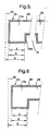
- FIG. 5 shows an end tooth 17a (comparable, for example, with the end tooth 17 in FIG. 3) of a "first" stator core (6c in FIG. 3) of a "first" stator core (6c in FIG. 3) of a "first" stator core (6c in FIG. 3) of a "first" stator core (6c in FIG. 3) of a "first" stator core (6c in FIG. 3) of a "first" stator core (6c in FIG. 3) of a "first" stator core (6c in FIG. 3) of a "first" stator core (6c in FIG. 3) of a "first" stator core (6c in FIG. 3) of a "first" stator core (6c in FIG. 3) of a "first" stator core (6c in FIG. 3) of a "first" stator core (6c in FIG. 3) of a "first" stator core (6c in FIG. 3) of a "first" stator core (6c in FIG. 3) of a
- the teeth 14 and grooves 15, viewed magnetically, for example, have a length of 43 mm, while the grooves 15, considered "material", because of the coating 29 only have a length of 43 mm - 2 mm 41 mm which is insignificant in magnetic terms.
- the coating 29 must be taken into account, because here two end teeth abut one another at an imaginary ideal line or plane 30.
- two stator packets are not adjacent to form an ideal gap of 0 mm, but real mounting column of z. B. 0.2 mm are to be considered. If, on each side of a stator packet, half of such a mounting gap is taken into consideration, as indicated by line 30 in FIG.
- Fig. 7 shows an end tooth 17 c for a Statorendvers 7 a in Fig. 2.
- the "ideal" length of 1024 mm is not calculated up to a line 30, which takes into account a mounting gap, but z. B. to the level 11 in Fig. 2, which also includes half of an expansion gap, ie additionally 8 mm gap width.
- the second end tooth of the stator core 7a corresponds to that of the stator core 6c of FIG. 5.
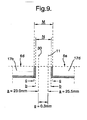
- Fig. 9 shows a joint between the stator 6d and 6e.
- the screening remains unchanged.
- the described central stator packets and Statorendwovene are suitably combined with each other so that - 1 mm ⁇ G ⁇ 2 mm
- G is the difference between the length of a space curve section between planes 11 and 12 associated with a stator section 6, 7, 26, 27 and the sum of the "ideal" lengths of the mean stator packets and stator end packets contained in that stator section.
- G is thus a measure of a total material gap width, which is to be taken into account within a stator section in addition to the mounting gaps and the gaps resulting from the coating.
- Another option is to change the length of the To distribute the end teeth alone on the existing teeth, which is a justifiable Length change of the teeth of 0.25 mm correspond and would have the advantage that the width of the grooves 15 remains unchanged, as is the case for a safe installation of the AC cable is desired.
- the invention was based on a carrier 1 with a between the points 18 and 19 measured length of 6192 mm. However, it is clear that carriers with other lengths can be used. According to the invention, it is proposed in addition to use two more carriers, about four or ten times as long as the carrier 1 and can be equipped with the same stator packets described. When using these carriers, the distance of the associated points 18,19 with z. B. 24768 mm or 61920 mm also equal to an integer multiple of both the Tooth / groove pitch 16 and the length of the "first" stator packs. These two carriers are hereinafter referred to as the carrier 1 as a series carrier.
- stator packs can be done in principle arbitrary. Preferably, however, the "second" stator packets only for outer and the “third” Stator packages used only for inner stator sections. It is also appropriate, the from the normal length (1032 mm) deviating stator packets evenly over the Distribute stator sections.
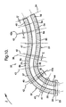
- FIG. 10 shows a guideway for a magnetic levitation railway with two lanes 31 and 32, have the curved and possibly also straight track sections.
- Each lane 31, 32 is formed analogously to the travel of Fig. 1 to 9 and therefore by a space curve 2a or 2b and two space curves 8a, 8b and 9a, 9b, respectively, characterizing the space curves 2, 8 and 9 correspond to FIGS. 2 and 4.
- the between The two compulsory points 33, 34 lying part of the infrastructure is below as Designated section 35.
- the production of the travel path within the projecting section 35 begins according to the invention in that first the distance between the compulsory points 33, 34 is determined so that the space curve 2a of that lane 31 which borders an external lane section 34 at the second constraining point 34 has a length, which exactly corresponds to an integer multiple of a preselected tooth / groove pitch (here, for example, 86 mm). This is easily possible, since the beginning of the special structure following the constraining point 34 can easily be moved forwards or backwards to the extent required for this purpose, which corresponds to half the tooth / groove pitch (here 43 mm).
- an outer lane section analogous to FIGS. 2 and 4 is understood to mean a lane section which lies on the outside in a curve of the travel path. If a straight lane section borders on the constraining point 34 (or also 33), then this is also referred to as the outer lane section, provided that the first section deviating from the straight section is an outer section. The same applies to the inner lane sections.
- the projecting of the support for the infrastructure is started by specifying at the constraining point 33 a series support 36 intended for the outer adjacent traffic lane section as described above.
- further supports 37 are planned for the outer lane section, specifically until a curvature change point 38 is reached, which is indicated here as a line running normal to the space curve 2b.
- the beginnings and ends of the series carriers 36 and 37 determine the positions for schematically indicated floating bearings 39 and 40 and the centers of the series carriers 36 and 37 the positions for corresponding fixed bearings 41, which are then calculated according to the usual methods and by the projecting of the associated supports or other substructures.
- Schematically indicated planes 42 and carrier beginnings and ends correspond in FIG. 2 and 4, the levels 11 and 12, on which the points 18 and 19 lie, and levels 43 or the carrier centers the levels 10, depending on the case and terrain, the levels 43 and the fixed bearing 41 may also be arranged off-center with respect to the carrier.
- a carrier 44 is provided for the inner lane section, the length of which originally corresponds to that of the series carrier 36, but is shortened by as many integer multiples of the tooth / groove pitch that the plane 42a decisive for its end offset by a measure w to the plane 42 which is smaller than half the tooth / groove pitch.
- the carrier 44 may project beyond this level beyond the plane 42 or terminate in front of this plane 42. Accordingly, with the projecting direction z following carrier, z.
- a carrier 45 which is attached to the carrier 44 in the same manner as described above in connection with FIGS. 1 to 9 in detail.
- this support 45 is, if necessary, again shortened by an integer multiple of the tooth / groove pitch, so that the offset v is less than 43 mm here.
- the outer carrier 37 protrudes by no more than half its length beyond the center of curvature 38, it forms the last serial carrier of the outer portion.
- the series carriers are used along the now outer traffic lane section of the traffic lane 31 by connecting a first series carrier 46 to the carrier 45, while on the now internal traffic lane section of the lane 32 carriers (eg 47) are used, which are integer Multiples of the tooth / groove pitch are shortened so that an offset x is less than 43 mm. This procedure is continued until either another turn point or constraint point 34 is reached.
- a carrier 48 which is smaller by an integer multiple of the tooth / groove pitch, and the same applies to a carrier 49 at the end of the inner lane section.
- serial carrier 37 used were so long that it was more than half its length protrudes beyond the curvature change point 38, would already at the previous Carrier started to change the lane for the series carriers, i. in this case
- the carrier 45 would already be a series carrier and the carrier 37 would be a shortened carrier.
- the method described has the significant advantage that the positions for the movable bearings 39, 40 result from the configuration of series carriers arranged along the two lanes 31, 32 and the same supports and substructures can be used for the movable bearings of the respective shortened carriers, because the offset u , v , w or x of the beam ends is comparatively small and at no point greater than 43 mm here.
- both the series carrier and the stator of the kit described can be used and internal support are only to be shortened.
- the procedure can be continued in an analogous manner by first planning a possibly existing special structure in the grid of 86 and then projecting the next section of track in the manner described.
- the entire distance to be produced can be planned in the grid once selected or divided into pieces with a length corresponding to the tooth / groove pitch and then projected in the preselected direction z .
- the invention is not limited to the described embodiments, which can be modified in many ways. This applies in particular to the described lengths, tooth / groove divisions, assembly gaps, expansion gaps and other dimensions. Corresponding kits of carriers and stator packages can of course be realized with other tooth / groove divisions. Furthermore, it would be possible, instead of just two different "second” or “third” stator packs and a “first” stator pack, to include further “first”, “second” and “third” stator packs with lengths other than those indicated and / or others to provide as the specified gradations or to omit one or the other "second” or “third” stator packet, in which case other inequalities for G may result.
Landscapes
- Engineering & Computer Science (AREA)
- Mechanical Engineering (AREA)
- Architecture (AREA)
- Civil Engineering (AREA)
- Structural Engineering (AREA)
- Linear Motors (AREA)
- Iron Core Of Rotating Electric Machines (AREA)
- Control Of Vehicles With Linear Motors And Vehicles That Are Magnetically Levitated (AREA)
- Hard Magnetic Materials (AREA)
- Railway Tracks (AREA)
Description
Claims (18)
- Fahrweg für eine Magnetschwebebahn mit einem wenigstens zwei parallele Statoren aufweisenden Langstator-Linearabtrieb, enthaltend: eine Vielzahl von längs einer Trasse angeordneten, zur Bildung von geraden und gekrümmten Fahrwegsabschnitten bestimmten Trägern (1) und an den Trägern (1) montierte Statorabschnitte, die längs paralleler, ihnen zugeordneter Raumkurvenabschnitte angeordnet und aus geraden Statorendpaketen (6a,f; 7a,f; 26a,f; 27a,f) und zwischen diesen angeordneten, ebenfalls geraden, mittleren Statorpaketen (6b-e; 7b-e; 26b-e; 27b-e) zusammengesetzt sind, die im Bereich der gekrümmten Fahrwegabschnitte unter Bildung von äußeren und inneren Statorabschnitten (6,7,26,27) nach Art von Polygonzügen verlegt und durch Spalte (23,24) voneinander getrennt sind, wobei die Statorendpakete (6a,f; 7a,f;26a,f;27a,f) und die mittleren Statorpakete (8b-e; 7b-e; 26b-e; 27b-e), bezogen auf eine zwischen den beiden Raumkurvenabschnitten liegende, gedachte Raumkurve (2), eine vorgewählte Zahn/Nut-Teilung (16) sowie unterschiedliche "ideelle" Längen aufweisen, die sich um Bruchteile einer Zahn/Nut-Teilung (16) voneiner unterscheiden und sich aus den Summen je eines Blechpaket-, Montagespalt- und Beschichtungsanteils ergeben, dadurch gekennzeichnet, daß die mittleren Statorpakete (6b-e; 7b-e; 26b-e; 27b-e) in wenigstens einem äußeren und inneren Statorabschnitt (6,7,26,27) unter Berücksichtigung ihrer unterschiedlichen "ideellen" Länge so miteinander kombiniert sind, daß ein "materieller" Gesamtspalt zwischen den Statorendpaketen (6a,f;7a,f; 26a,f;27a,f) und den mittleren Statorpaketen (6b-e; 7b-e; 26b-e; 27b-e) dieses Statorabschnitts (6,7,26,27) die kleinste mögliche Breite aufweist, wobei der "materielle" Gesamtspalt die Differenz zwischen der Länge eines diesem Statorabschnitt (6,7,26,27) zugeordneten Raumkurvenabschnitts (8,9) und der Summe der "ideellen" Längen der in diesem Statorabschnitt (6,7,26,27) liegenden Statorendpakete (6a,f; 7a,f; 26a,f; 27a,f) und der mittleren Statorpakete (6b-e; 7b-e; 26b-e; 27b-e) ist.
- Fahrweg nach Anspruch 1, dadurch gekennzeichnet, daß die mittleren Statorpakete erste Statorpakete (6c, 26b-e; 27b,c,e) mit einer "ideellen" Länge enthalten, die einem ganzzahligen Vielfachen der Zahn/Nut-Teilung (16) entspricht.
- Fahrweg nach Anspruch 2, dadurch gekennzeichnet, daß die mittleren Statorpakete zweite und dritte Statorpakete (6b,d,e; 7b-e; 27d) enthalten, deren "ideelle" Längen um Bruchteile einer Zahn/Nut-Teilung (16) größer bzw. kleiner als Längen der ersten Statorpakete (6c; 26b-e; 27b,c,e) sind.
- Fahrweg nach einem der Ansprüche 1 bis 3, dadurch gekennzeichnet, daß die Träger (1) zwischen Punkten (18,19) der Raumkurve (2) verlegt sind, die Abstände voneinander aufweisen, die einem ganzzahligen Vielfachen der Zahn/Nut-Teilung (16) entsprechen.
- Fahrweg nach Anspruch 4, dadurch gekennzeichnet, daß die Abstände der Punkte (18,19) überwiegend auch ganzzahligen Vielfachen der "ideellen" Längen der ersten Statorpakete (6c; 26b-e; 27b,c,e) entsprechen.
- Fahrweg nach einem der Ansprüche 1 bis 5, dadurch gekennzeichnet, daß zwischen in Trassenrichtung aneinander grenzenden Statorabschnitten zweier Träger (1) jeweils Dehnungsspalte (20a,21a) vorgesehen sind und diesen zugeordnete Statorendpakete (6a,f; 7a,f; 26a,f; 27a,f) eine Länge aufweisen, die unter Berücksichtigung der Größen der Dehnungsspalte (20a,21a) eine "materielle" Länge aufweisen, die uni einen Bruchteil einer Zahn/Nut-Teilung (16) kleiner als die Länge der ersten Statorpakete (6c; 26b-e; 27b,c,e) ist.
- Fahrweg nach einem der Ansprüche 1 bis 6, dadurch gekennzeichnet, daß zwischen in Trassenrichtung aneinander grenzenden Statorabschnitten zweier Träger (1) jeweils Dehnungsspalte (20a,21a) vorgesehen und diesen zugeordnete Statorendpakete im Vergleich zu den ersten Statorpaketen (6c; 26b-e; 27b,c,e) um eine Zahn/Nut-Teilung (16) gekürzt sind.
- Fahrweg nach einem der Ansprüche 4 bis 7, dadurch gekennzeichnet, daß die Punkte (18,19) auf normal zur Raumkurve (2) gerichteten Ebenen (11,12) liegen.
- Fahrweg nach einem der Ansprüche 3 bis 8, dadurch gekennzeichnet, daß die zweiten und dritten Statorpakete (6b,d,e bzw. 7b-e,27d) und die Statorendpakete (6a,f; 7a,f; 26a,f; 27a,f) eine der Zahn/Nut-Teilung (16) der ersten Statorpakete (6c; 26b-e; 26b,c,e) entsprechende Zahn/Nut-Teilung (16) aufweisen und die größere bzw. kleinere "ideelle" Länge durch entsprechende Verlängerung bzw. Verkürzung von Endzähnen (17b,c) erhalten wird.
- Fahrweg nach einem der Ansprüche 3 bis 8, dadurch gekennzeichnet, daß die zweiten und dritten Statorpakete und die Statorendpakete eine Zahn/Nut-Teilung aufweisen, die um ein ihrer größeren bzw. kleineren "ideellen" Länge entsprechendes Maß größer bzw. kleiner als die Zahn/Nut-Teilung der ersten Statorpakete (6; 26b-e; 27b,c,e) ist.
- Fahrweg nach einem der Ansprüche 3 bis 8, dadurch gekennzeichnet, daß die zweiten und dritten Statorpakete und die Statorendpakete bei unveränderter Nutbreite eine Zahnbreite aufweisen, die um ein ihrer größeren bzw. kleineren "ideellen" Länge entsprechendes Maß größer bzw. kleiner als die Zahnbreite der ersten Statorpakete ist.
- Fahrweg nach einem der Ansprüche 1 bis 11, dadurch gekennzeichnet, daß er unter Anwendung einer vorgewählten kleinen Anzahl von Trägertypen bzw. Serienträgern mit unterschiedlichen Längen hergestellt ist, die jeweils zwischen Punkten (18,19) angeordnet sind, deren Abstände unterschiedlichen ganzzahlingen Vielfachen der Zahn/Nut-Teilung (16) und unterschiedlichen ganzzahlingen Vielfachen der ersten Statorpakete (6b; 26b-e; 27b,c,e) entsprechen.
- Fahrweg nach einem der Ansprüche 1 bis 12, dadurch gekennzeichnet, daß die zweiten Statorpakete (6b,d,e) nur innerhalb der äußeren Statorabschnitte (6,27) vorgesehen sind.
- Fahrweg nach einem der Ansprüche 1 bis 13, dadurch gekennzeichnet, daß die Statorendpakete (6a,f; 7a,f; 26a,f; 27a,f) und die mittleren Statorpakete (6b-e; 7b-e; 26b-e; 27b-e) innerhalb der äußeren und inneren Statorabschnitte (6,7,26,27) so miteinanderkombiniert sind, daß - 1 mm ≤ G < 2 mm gilt, worin G die Differenz zwischen den Längen der den Statorabschnitten (6,7,26,27) zugeordneten Raumkurvenabschnitten und den Summen der "ideellen" Längen der in den Statorabschnitten (6,7,26,27) enthaltenen Statorendpakete (6a,f; 7a,f; 26a,f; 27a,f) und mittleren Statorpakete (6b-e; 7b-e; 26b-e; 27b-e) ist.
- Bausatz zur Herstellung von Fahrwegen nach einem der Ansprüche 1 bis 14 für eine Magnetschwebebahn mit einem wenigstens zwei parallele Statoren aufweisenden Langstator-Linearmotor, dadurch gekennzeichnet, daß er eine Vielzahl der ersten, zweiten und dritten Statorpakete (6b-e; 7b-e; 26b-e; 27b-e) und der Statorendpakete (6a,f; 7a,f; 26a,f; 27a,f) entsprechend wenigstens einem der Ansprüche 3,7,9,10 und 11 sowie Serienträger (1) entsprechend Anspruch 12 enthält.
- Verfahren zur Herstellung eines Fahrwegs für eine Magnetschwebebahn mit gekrümmten und ggf. auch geraden Fahrwegabschnitten, die wenigstens zwei Fahrspuren (31,32) bilden, mit Statoren von je einem Langstator-Linearmotor pro Fahrspur versehen sind und entsprechend ihren Krümmungen äußere und innere Fahrspurabschnitte aufweisen, wobei läng einer vorgegebenen Trasse zwei den Fahrspuren (31,32) zugeordnete Raumkurven (2a,2b), wenigstens ein erster und ein zweiter Zwangspunkt (33,34) und ein zwischen diesen angeordneter Projektierungsabschnitt (35) festgelegt, längs des Projektierungsabschnitts (35) Träger (36,37,44-49) und deren Lager für den Fahrweg und die Statoren angeordnet und die Träger (36,37,44-49) mit die Statoren bildenden Statorpaketen versehen werden, dadurch gekennzeichnet, daß der Abstand zwischen den beiden Zwangspunkten (33,34) so festgelgt wird, daß die Raumkurve (2a) derjenigen Fahrspur (31), die mit einem äußeren Fahrspurabschnitt an den zweiten Zwangspunkt (34) grenzt, eine Länge besitzt, die einem ganzzahlingen Vielfachen einer vorgewählten Zahn/Nut-Teilung (16) für den Fahrweg entspricht, daß ferner, beginnend am ersten Zwangspunkt (33), längs der jeweiligen äußeren Fahrspurabschnitte Serienträger (36,37,46,48) aus dem Bausatz nach Anspruch 15 angeordnet werden, während längs der jeweils inneren Fahrspurabschnitte Träger (44,45,47,49) angeordnet werden, die gegenüber den Serienträgern (36,37,46,48) um ganzzahlige Vielfache der Zahn/Nut-Teilung (16) gekürzt sind, wobei die Kürzung dieser Träger (44,45,47,49) derart erfolgt, daß ihre Enden gegenüber den Enden eines zugeordneten Serienträgers(36,37,46,48) des äußeren Fahrspurabschnitts höchstens um je eine halbe Zahn/Nut-Teilung versetzt sind, und daß alle Träger (36,37,44-49) unter Herstellung eines Fahrwegs nach wenigstens einem der Ansprüche 1 bis 14 mit Statorpaketen und Statorendpaketen aus dem Bausatz nach Anspruch 15 ausgerüstet werden.
- Verfahren nach Anspruch 16, dadurch gekennzeichnet, daß für den Fall, daß der letzte Träger (48) des an den zweiten Zwangspunkt (34) grenzenden äußeren Fahrspurabschnitts eine den zweiten Zwangspunkt (34) überragende Länge besitzt, so um ein ganzzahliges Vielfaches der Zahn/Nut-Teilung (16) gekürzt wird, daß er ohne Versatz an den zweiten Zwangspunkt (34) grenzt.
- Verfahren nach Anspruch 16, oder 17, dadurch gekennzeichnet, daß beim Erreichen eines Krümmungswechselpunktes (38) der diesen überquerende Serienträger (37) nur dann längs des vor dem Krümmungswechselpunkt (38) äußeren Fahrspurabschnitts verlegt wird, wenn er den Krümmungswechselpunkt (38) um nicht mehr als die Hälfte seiner Länge überquert, andern falls auf demjenigen Fahrspurabschnitt angeordnet wird, der hinter dem Krümmungswechselpunkt (38) außen liegt.
Applications Claiming Priority (2)
| Application Number | Priority Date | Filing Date | Title |
|---|---|---|---|
| DE19934912 | 1999-07-21 | ||
| DE19934912A DE19934912A1 (de) | 1999-07-21 | 1999-07-21 | Fahrweg für eine Magnetschwebebahn mit Langsstator- Linearantrieb sowie Bausatz und Verfahren zu seiner Herstellung |
Publications (3)
| Publication Number | Publication Date |
|---|---|
| EP1070786A2 EP1070786A2 (de) | 2001-01-24 |
| EP1070786A3 EP1070786A3 (de) | 2001-06-27 |
| EP1070786B1 true EP1070786B1 (de) | 2005-12-07 |
Family
ID=7916021
Family Applications (1)
| Application Number | Title | Priority Date | Filing Date |
|---|---|---|---|
| EP00115723A Expired - Lifetime EP1070786B1 (de) | 1999-07-21 | 2000-07-21 | Fahrweg für eine Magnetschwebebahn mit Langstator-Linearantrieb sowie Bausatz und Verfahren zu seiner Herstellung |
Country Status (10)
| Country | Link |
|---|---|
| US (1) | US6568332B1 (de) |
| EP (1) | EP1070786B1 (de) |
| JP (1) | JP2001073304A (de) |
| CN (1) | CN1278894C (de) |
| AT (1) | ATE312240T1 (de) |
| AU (1) | AU771673B2 (de) |
| CA (1) | CA2314161A1 (de) |
| DE (2) | DE19934912A1 (de) |
| DK (1) | DK1070786T3 (de) |
| RU (1) | RU2271414C2 (de) |
Families Citing this family (31)
| Publication number | Priority date | Publication date | Assignee | Title |
|---|---|---|---|---|
| DE10110613B4 (de) * | 2001-03-06 | 2009-06-10 | Otmar Fahrion | Fahrwegsegment für eine Magnetschwebebahn |
| DE10111919A1 (de) * | 2001-03-13 | 2002-09-19 | Boegl Max Bauunternehmung Gmbh | Fahrwegträger |
| DE50306008D1 (de) * | 2002-04-10 | 2007-02-01 | Transrapid Int Gmbh & Co Kg | Vorrichtung zum Betreiben eines Magnetfahrzeugs |
| DE10227253A1 (de) * | 2002-04-10 | 2003-10-23 | Transrapid Int Gmbh & Co Kg | Vorrichtung zum Betreiben eines Magnetfahrzeugs |
| WO2003102304A1 (de) * | 2002-05-28 | 2003-12-11 | Thyssenkrupp Technologies Ag | Fahrweg für magnetschwebefahrzeuge |
| DE10317014A1 (de) * | 2003-04-11 | 2004-10-21 | Max Bögl Bauunternehmung GmbH & Co. KG | Fahrweg für ein spurgebundenes Fahrzeug mit einem wenigstens einen Langstator aufweisenden Langstator-Linearantrieb sowie einen Bausatz und ein Statorpaket zu seiner Herstellung |
| DE102004012746A1 (de) * | 2004-03-15 | 2005-10-06 | Thyssenkrupp Transrapid Gmbh | Magnetanordnung für ein Magnetschwebefahrzeug |
| DE102004012748A1 (de) * | 2004-03-15 | 2005-10-06 | Thyssenkrupp Transrapid Gmbh | Magnetanordnung für ein Magnetschwebefahrzeug |
| DE102006043378A1 (de) * | 2006-09-12 | 2008-03-27 | Thyssenkrupp Transrapid Gmbh | Magnetanordnung für Magnetschwebefahrzeuge |
| NL2002682C2 (nl) * | 2009-03-30 | 2010-10-04 | Roof Safety Systems B V | Beveiligingsconstructie voor een spoorlijn. |
| DE102009002612B4 (de) * | 2009-04-23 | 2017-07-06 | Robert Bosch Gmbh | Umlaufende Transportvorrichtung mit verbessertem Antriebskonzept |
| DE102009002606A1 (de) * | 2009-04-23 | 2010-10-28 | Robert Bosch Gmbh | Umlaufende Transportvorrichtung mit verbessertem Antriebskonzept |
| DE102009002609A1 (de) * | 2009-04-23 | 2010-10-28 | Robert Bosch Gmbh | Umlaufende Transportvorrichtung mit verbessertem Antriebskonzept |
| DE102009049225A1 (de) | 2009-10-09 | 2011-05-05 | Thyssenkrupp Transrapid Gmbh | Muffe zur Verbindung der Enden von Wicklungen eines Langstator-Linearmotors und damit ausgerüsteter Langstator |
| KR101069707B1 (ko) | 2010-03-30 | 2011-10-05 | (주)시아이에스 | 흡인식 자기부상 열차용 추진레일 및 그 추진레일의 제조방법 |
| CN101851882B (zh) * | 2010-06-18 | 2011-11-30 | 北京交通大学 | 跨座式单轨交通曲线轨道梁变窄方法 |
| DE102012204919A1 (de) * | 2012-03-27 | 2013-10-02 | Beckhoff Automation Gmbh | Statorvorrichtung für einen linearmotor und lineares transportsystem |
| DE102012204916A1 (de) | 2012-03-27 | 2013-10-02 | Beckhoff Automation Gmbh | Statorvorrichtung für einen Linearmotor und lineares Transportsystem |
| DE102012204917A1 (de) | 2012-03-27 | 2013-10-02 | Beckhoff Automation Gmbh | Positionserfassungsvorrichtung und Verfahren zum Erfassen einer Position eines beweglichen Elements einer Antriebsvorrichtung |
| DE102012220008B4 (de) * | 2012-11-02 | 2023-06-01 | Syntegon Technology Gmbh | Transportvorrichtung mit steuerbarem Förderelement |
| AT518618B1 (de) * | 2016-05-09 | 2021-10-15 | B & R Ind Automation Gmbh | Baukastensystem aus einer Vielzahl von Transportstreckenbaugruppen eines Langstatorlinearmotors |
| CN111051227B (zh) | 2017-09-13 | 2022-08-16 | 莱特拉姆有限责任公司 | 带有无源导轨的单轨托盘输送机 |
| US10807803B2 (en) | 2018-01-31 | 2020-10-20 | Laitram, L.L.C. | Hygienic low-friction magnetic tray and conveyor |
| US10654660B2 (en) * | 2018-01-31 | 2020-05-19 | Laitram, L.L.C. | Hygienic magnetic tray and conveyor |
| CN112281553A (zh) * | 2020-10-10 | 2021-01-29 | 中铁第四勘察设计院集团有限公司 | 一种磁悬浮桥梁结构 |
| DE102020134829A1 (de) * | 2020-12-23 | 2022-06-23 | Max Bögl Stiftung & Co. Kg | Fahrwegträger einer Magnetschwebebahn |
| DE102020134832A1 (de) | 2020-12-23 | 2022-06-23 | Max Bögl Stiftung & Co. Kg | Betonträger einer Magnetschwebebahn |
| CN112695605B (zh) * | 2020-12-31 | 2025-12-05 | 中铁第四勘察设计院集团有限公司 | 磁悬浮交通的预制功能面板、板梁结构及施工方法 |
| CN113408026B (zh) * | 2021-06-16 | 2023-06-20 | 中国铁路设计集团有限公司 | 一种铁路桥梁精准弯道布置计算方法 |
| CN116177175B (zh) * | 2023-01-31 | 2024-01-30 | 果栗智造(上海)技术股份有限公司 | 一种接驳装置及输送线体 |
| CN116377774B (zh) * | 2023-06-05 | 2023-08-18 | 成都西交华创科技有限公司 | 用于永磁轨道的伸缩缝补偿装置及补偿方法 |
Family Cites Families (19)
| Publication number | Priority date | Publication date | Assignee | Title |
|---|---|---|---|---|
| JPS4824417B1 (de) * | 1970-07-08 | 1973-07-20 | ||
| JPS4862114A (de) * | 1971-11-30 | 1973-08-30 | ||
| CA1044774A (en) * | 1974-07-26 | 1978-12-19 | Gotz Heidelberg | Magnetic system for supporting and propelling a vehicle along a roadway |
| JPS558922A (en) * | 1978-06-30 | 1980-01-22 | Tokyo Shibaura Electric Co | Construction of track and vehicle magnetically buoyed up by ordinary conduction |
| JPS57193601A (en) * | 1981-05-22 | 1982-11-29 | Nihon Koukuu Kk | Construction of curved rail of suction type magnetic float running system |
| DE3323696A1 (de) | 1983-07-01 | 1985-01-10 | Thyssen Industrie Ag, 4300 Essen | Verfahren und vorrichtung zum verlegen einer vorgefertigten wicklung eines linearmotors |
| DE3335058A1 (de) * | 1983-09-28 | 1985-04-04 | Dyckerhoff & Widmann AG, 8000 München | Zweibahnige, aufgestaenderte fahrwegkonstruktion fuer magnetschwebefahrzeuge |
| EP0144000B1 (de) * | 1983-11-04 | 1991-07-24 | Fuji Electric Corporate Research And Development Ltd. | Schwebevorrichtung für Schwebefahrzeug mit magnetischer Anziehung |
| DE3404061C1 (de) | 1984-02-06 | 1985-09-05 | Thyssen Industrie Ag, 4300 Essen | Verfahren zur Iagegenauen Befestigung von Ausruestungsteilen an vorgegebenen Anschlussorten an der Tragkonstruktion von Fahrwegen |
| DE3700774C2 (de) * | 1986-01-13 | 1998-11-12 | Papst Motoren Gmbh & Co Kg | Kollektorlose Gleichstrommaschine |
| JP2585409B2 (ja) * | 1988-12-16 | 1997-02-26 | 株式会社日立製作所 | 超電導マグネット装置、その冷却システム及びこれらを備えた磁気浮上走行装置 |
| DE3928278A1 (de) | 1989-07-25 | 1991-02-07 | Thyssen Industrie | Tragkonstruktion fuer den fahrweg eines spurgebundenen fahrzeugs, insbesondere einer magnetschwebebahn |
| DE3928277C1 (de) | 1989-07-25 | 1990-12-13 | Thyssen Industrie Ag, 4300 Essen, De | |
| JP3092723B2 (ja) * | 1990-06-20 | 2000-09-25 | 株式会社安川電機 | 水中リニア輸送システム |
| JPH0834684B2 (ja) * | 1990-11-30 | 1996-03-29 | 財団法人鉄道総合技術研究所 | 磁気浮上車両の推進装置 |
| JP2986935B2 (ja) * | 1991-02-25 | 1999-12-06 | 中部エィチ・エス・エス・ティ開発株式会社 | リニアモーターカー浮上用マグネット |
| JPH05130765A (ja) * | 1991-11-01 | 1993-05-25 | Hitachi Kiden Kogyo Ltd | 曲路用リニアモータ |
| DE4434121A1 (de) * | 1994-09-23 | 1996-03-28 | Thyssen Industrie | Verfahren und Vorrichtung zur lagegenauen Anordnung von Funktionskomponenten an der Tragkonstruktion von Fahrwegen für spurgebundene Fahrzeuge, insbesondere Magnetschwebebahnen |
| DE19620221A1 (de) | 1995-10-30 | 1997-05-07 | Thyssen Industrie | Langstator für einen Linearmotor und zur Herstellung des Langstators bestimmtes Blechpaket |
-
1999
- 1999-07-21 DE DE19934912A patent/DE19934912A1/de not_active Withdrawn
-
2000
- 2000-07-19 US US09/619,726 patent/US6568332B1/en not_active Expired - Fee Related
- 2000-07-19 CA CA002314161A patent/CA2314161A1/en not_active Abandoned
- 2000-07-20 RU RU2000119432/11A patent/RU2271414C2/ru not_active IP Right Cessation
- 2000-07-20 CN CN00120183.2A patent/CN1278894C/zh not_active Expired - Lifetime
- 2000-07-21 DK DK00115723T patent/DK1070786T3/da active
- 2000-07-21 AU AU48774/00A patent/AU771673B2/en not_active Ceased
- 2000-07-21 DE DE50011797T patent/DE50011797D1/de not_active Expired - Lifetime
- 2000-07-21 EP EP00115723A patent/EP1070786B1/de not_active Expired - Lifetime
- 2000-07-21 JP JP2000221077A patent/JP2001073304A/ja not_active Ceased
- 2000-07-21 AT AT00115723T patent/ATE312240T1/de not_active IP Right Cessation
Also Published As
| Publication number | Publication date |
|---|---|
| HK1036255A1 (en) | 2001-12-28 |
| CA2314161A1 (en) | 2001-01-21 |
| EP1070786A3 (de) | 2001-06-27 |
| DK1070786T3 (da) | 2006-04-18 |
| EP1070786A2 (de) | 2001-01-24 |
| CN1278894C (zh) | 2006-10-11 |
| CN1295000A (zh) | 2001-05-16 |
| AU4877400A (en) | 2001-01-25 |
| US6568332B1 (en) | 2003-05-27 |
| JP2001073304A (ja) | 2001-03-21 |
| AU771673B2 (en) | 2004-04-01 |
| RU2271414C2 (ru) | 2006-03-10 |
| DE50011797D1 (de) | 2006-01-12 |
| DE19934912A1 (de) | 2001-01-25 |
| ATE312240T1 (de) | 2005-12-15 |
Similar Documents
| Publication | Publication Date | Title |
|---|---|---|
| EP1070786A2 (de) | Fahrweg für eine Magnetschwebebahn mit Langstator-Linearantrieb sowie Bausatz und Verfahren zu seiner Herstellung | |
| EP2789082B1 (de) | Linear-synchronmotor | |
| EP2064087B1 (de) | Magnetschwebefahrzeug mit führmagneten | |
| EP1725423A1 (de) | Führmagnetsystem und damit ausgerüstetes magentschwebefahrzeug | |
| DE29809580U1 (de) | Fahrwegplatte für die Fahrbahn von Magnetbahnzügen | |
| DE2239656A1 (de) | Fahrbahnkoerper fuer hochleistungsschnellbahnen | |
| EP1613811B1 (de) | Fahrweg für ein spurgebundenes fahrzeug mit einem wenigstens einen langstator aufweisenden langstator-linearantrieb sowie einen bausatz und ein statorpaket zu seiner herstellung | |
| DE10253136A1 (de) | Funktionsebenenträger | |
| DE3111385C2 (de) | Stahlfahrweg für Magnetbahnen | |
| WO2003102303A1 (de) | Fahrweg, fahrwegmodul und verfahren zu dessen herstellung | |
| DE9304251U1 (de) | Stromabnehmer | |
| DE2853489C2 (de) | Magnetschwebebahn | |
| DE102020134829A1 (de) | Fahrwegträger einer Magnetschwebebahn | |
| DE3335058A1 (de) | Zweibahnige, aufgestaenderte fahrwegkonstruktion fuer magnetschwebefahrzeuge | |
| DE4416821C2 (de) | System von Übergängen, wie Weichen | |
| DE10224148A1 (de) | Fahrweg, Fahrwegmodul und Verfahren zu dessen Herstellung | |
| DE2314119A1 (de) | Doppelweiche | |
| DE2900053A1 (de) | Stosskonstruktion fuer magnetschienen von hochleistungs-schnellbahnen | |
| DE20208421U1 (de) | Biegeträger aus Stahl für eine Spurwechseleinrichtung bei Fahrwegen von Magnetschwebefahrzeugen | |
| DE202008016183U1 (de) | Fahrwegträger für Magnetschwebefahrzeuge und Statorpaket dafür | |
| EP1900084B1 (de) | Vorrichtung und verfahren zum verarbeiten, aufnehmen und/oder montieren eines elektrischen leiters | |
| DE3233032A1 (de) | Eisenkern fuer dreiphasige elektromagnetische induktionsmaschinen | |
| EP2280844B1 (de) | Magnetschwebefahrzeug mit einer mehrzahl von führ- und bremsmagneten | |
| DE3329788C2 (de) | Fahrbahn für Spurbusse | |
| DE102024103720A1 (de) | Primäreinheit, Verwendung einer Wicklung, Antriebsvorrichtung sowie Magnetschwebebahn |
Legal Events
| Date | Code | Title | Description |
|---|---|---|---|
| PUAI | Public reference made under article 153(3) epc to a published international application that has entered the european phase |
Free format text: ORIGINAL CODE: 0009012 |
|
| AK | Designated contracting states |
Kind code of ref document: A2 Designated state(s): AT BE CH CY DE DK ES FI FR GB GR IE IT LI LU MC NL PT SE |
|
| AX | Request for extension of the european patent |
Free format text: AL;LT;LV;MK;RO;SI |
|
| PUAL | Search report despatched |
Free format text: ORIGINAL CODE: 0009013 |
|
| AK | Designated contracting states |
Kind code of ref document: A3 Designated state(s): AT BE CH CY DE DK ES FI FR GB GR IE IT LI LU MC NL PT SE |
|
| AX | Request for extension of the european patent |
Free format text: AL;LT;LV;MK;RO;SI |
|
| 17P | Request for examination filed |
Effective date: 20010821 |
|
| AKX | Designation fees paid |
Free format text: AT BE CH CY DE DK ES FI FR GB GR IE IT LI LU MC NL PT SE |
|
| 17Q | First examination report despatched |
Effective date: 20040414 |
|
| GRAP | Despatch of communication of intention to grant a patent |
Free format text: ORIGINAL CODE: EPIDOSNIGR1 |
|
| GRAS | Grant fee paid |
Free format text: ORIGINAL CODE: EPIDOSNIGR3 |
|
| GRAA | (expected) grant |
Free format text: ORIGINAL CODE: 0009210 |
|
| AK | Designated contracting states |
Kind code of ref document: B1 Designated state(s): AT BE CH CY DE DK ES FI FR GB GR IE IT LI LU MC NL PT SE |
|
| PG25 | Lapsed in a contracting state [announced via postgrant information from national office to epo] |
Ref country code: IE Free format text: LAPSE BECAUSE OF FAILURE TO SUBMIT A TRANSLATION OF THE DESCRIPTION OR TO PAY THE FEE WITHIN THE PRESCRIBED TIME-LIMIT Effective date: 20051207 Ref country code: FI Free format text: LAPSE BECAUSE OF FAILURE TO SUBMIT A TRANSLATION OF THE DESCRIPTION OR TO PAY THE FEE WITHIN THE PRESCRIBED TIME-LIMIT Effective date: 20051207 |
|
| REG | Reference to a national code |
Ref country code: GB Ref legal event code: FG4D Free format text: NOT ENGLISH |
|
| REG | Reference to a national code |
Ref country code: CH Ref legal event code: EP |
|
| REG | Reference to a national code |
Ref country code: IE Ref legal event code: FG4D Free format text: LANGUAGE OF EP DOCUMENT: GERMAN |
|
| REF | Corresponds to: |
Ref document number: 50011797 Country of ref document: DE Date of ref document: 20060112 Kind code of ref document: P |
|
| PG25 | Lapsed in a contracting state [announced via postgrant information from national office to epo] |
Ref country code: GR Free format text: LAPSE BECAUSE OF FAILURE TO SUBMIT A TRANSLATION OF THE DESCRIPTION OR TO PAY THE FEE WITHIN THE PRESCRIBED TIME-LIMIT Effective date: 20060307 Ref country code: SE Free format text: LAPSE BECAUSE OF FAILURE TO SUBMIT A TRANSLATION OF THE DESCRIPTION OR TO PAY THE FEE WITHIN THE PRESCRIBED TIME-LIMIT Effective date: 20060307 |
|
| PG25 | Lapsed in a contracting state [announced via postgrant information from national office to epo] |
Ref country code: ES Free format text: LAPSE BECAUSE OF FAILURE TO SUBMIT A TRANSLATION OF THE DESCRIPTION OR TO PAY THE FEE WITHIN THE PRESCRIBED TIME-LIMIT Effective date: 20060318 |
|
| GBT | Gb: translation of ep patent filed (gb section 77(6)(a)/1977) |
Effective date: 20060315 |
|
| REG | Reference to a national code |
Ref country code: CH Ref legal event code: NV Representative=s name: E. BLUM & CO. PATENTANWAELTE |
|
| REG | Reference to a national code |
Ref country code: DK Ref legal event code: T3 |
|
| PG25 | Lapsed in a contracting state [announced via postgrant information from national office to epo] |
Ref country code: PT Free format text: LAPSE BECAUSE OF FAILURE TO SUBMIT A TRANSLATION OF THE DESCRIPTION OR TO PAY THE FEE WITHIN THE PRESCRIBED TIME-LIMIT Effective date: 20060508 |
|
| REG | Reference to a national code |
Ref country code: IE Ref legal event code: FD4D |
|
| PG25 | Lapsed in a contracting state [announced via postgrant information from national office to epo] |
Ref country code: MC Free format text: LAPSE BECAUSE OF NON-PAYMENT OF DUE FEES Effective date: 20060731 |
|
| ET | Fr: translation filed | ||
| PLBE | No opposition filed within time limit |
Free format text: ORIGINAL CODE: 0009261 |
|
| STAA | Information on the status of an ep patent application or granted ep patent |
Free format text: STATUS: NO OPPOSITION FILED WITHIN TIME LIMIT |
|
| 26N | No opposition filed |
Effective date: 20060908 |
|
| REG | Reference to a national code |
Ref country code: CH Ref legal event code: PFA Owner name: TRANSRAPID INTERNATIONAL GMBH & CO.KG Free format text: TRANSRAPID INTERNATIONAL GMBH & CO.KG#PASCALSTRASSE 10 F#10587 BERLIN (DE) -TRANSFER TO- TRANSRAPID INTERNATIONAL GMBH & CO.KG#PASCALSTRASSE 10 F#10587 BERLIN (DE) |
|
| PG25 | Lapsed in a contracting state [announced via postgrant information from national office to epo] |
Ref country code: LU Free format text: LAPSE BECAUSE OF NON-PAYMENT OF DUE FEES Effective date: 20060721 |
|
| PGFP | Annual fee paid to national office [announced via postgrant information from national office to epo] |
Ref country code: CH Payment date: 20080815 Year of fee payment: 9 Ref country code: DK Payment date: 20080721 Year of fee payment: 9 |
|
| PG25 | Lapsed in a contracting state [announced via postgrant information from national office to epo] |
Ref country code: CY Free format text: LAPSE BECAUSE OF FAILURE TO SUBMIT A TRANSLATION OF THE DESCRIPTION OR TO PAY THE FEE WITHIN THE PRESCRIBED TIME-LIMIT Effective date: 20051207 |
|
| PGFP | Annual fee paid to national office [announced via postgrant information from national office to epo] |
Ref country code: AT Payment date: 20080711 Year of fee payment: 9 Ref country code: FR Payment date: 20080718 Year of fee payment: 9 Ref country code: IT Payment date: 20080729 Year of fee payment: 9 Ref country code: NL Payment date: 20080703 Year of fee payment: 9 |
|
| PGFP | Annual fee paid to national office [announced via postgrant information from national office to epo] |
Ref country code: BE Payment date: 20090126 Year of fee payment: 9 |
|
| BERE | Be: lapsed |
Owner name: *TRANSRAPID INTERNATIONAL G.M.B.H. & CO. K.G. Effective date: 20090731 |
|
| REG | Reference to a national code |
Ref country code: CH Ref legal event code: PL |
|
| REG | Reference to a national code |
Ref country code: DK Ref legal event code: EBP |
|
| NLV4 | Nl: lapsed or anulled due to non-payment of the annual fee |
Effective date: 20100201 |
|
| REG | Reference to a national code |
Ref country code: FR Ref legal event code: ST Effective date: 20100331 |
|
| PG25 | Lapsed in a contracting state [announced via postgrant information from national office to epo] |
Ref country code: CH Free format text: LAPSE BECAUSE OF NON-PAYMENT OF DUE FEES Effective date: 20090731 Ref country code: FR Free format text: LAPSE BECAUSE OF NON-PAYMENT OF DUE FEES Effective date: 20090731 Ref country code: LI Free format text: LAPSE BECAUSE OF NON-PAYMENT OF DUE FEES Effective date: 20090731 |
|
| PG25 | Lapsed in a contracting state [announced via postgrant information from national office to epo] |
Ref country code: AT Free format text: LAPSE BECAUSE OF NON-PAYMENT OF DUE FEES Effective date: 20090721 Ref country code: BE Free format text: LAPSE BECAUSE OF NON-PAYMENT OF DUE FEES Effective date: 20090731 |
|
| PG25 | Lapsed in a contracting state [announced via postgrant information from national office to epo] |
Ref country code: DK Free format text: LAPSE BECAUSE OF NON-PAYMENT OF DUE FEES Effective date: 20090731 |
|
| REG | Reference to a national code |
Ref country code: GB Ref legal event code: 732E Free format text: REGISTERED BETWEEN 20110113 AND 20110119 |
|
| PG25 | Lapsed in a contracting state [announced via postgrant information from national office to epo] |
Ref country code: IT Free format text: LAPSE BECAUSE OF NON-PAYMENT OF DUE FEES Effective date: 20090721 |
|
| REG | Reference to a national code |
Ref country code: DE Ref legal event code: R082 Ref document number: 50011797 Country of ref document: DE Representative=s name: ANDREJEWSKI - HONKE PATENT- UND RECHTSANWAELTE, DE |
|
| PGFP | Annual fee paid to national office [announced via postgrant information from national office to epo] |
Ref country code: GB Payment date: 20110721 Year of fee payment: 12 |
|
| REG | Reference to a national code |
Ref country code: DE Ref legal event code: R082 Ref document number: 50011797 Country of ref document: DE Representative=s name: ANDREJEWSKI - HONKE PATENT- UND RECHTSANWAELTE, DE |
|
| REG | Reference to a national code |
Ref country code: DE Ref legal event code: R082 Ref document number: 50011797 Country of ref document: DE Representative=s name: ANDREJEWSKI - HONKE PATENT- UND RECHTSANWAELTE, DE Effective date: 20120110 Ref country code: DE Ref legal event code: R081 Ref document number: 50011797 Country of ref document: DE Owner name: THYSSENKRUPP TRANSRAPID GMBH, DE Free format text: FORMER OWNER: TRANSRAPID INTERNATIONAL GMBH & CO. KG, 10587 BERLIN, DE Effective date: 20120110 Ref country code: DE Ref legal event code: R082 Ref document number: 50011797 Country of ref document: DE Representative=s name: ANDREJEWSKI - HONKE PATENT- UND RECHTSANWAELTE, DE Effective date: 20110915 |
|
| PG25 | Lapsed in a contracting state [announced via postgrant information from national office to epo] |
Ref country code: NL Free format text: LAPSE BECAUSE OF NON-PAYMENT OF DUE FEES Effective date: 20100201 |
|
| GBPC | Gb: european patent ceased through non-payment of renewal fee |
Effective date: 20120721 |
|
| PG25 | Lapsed in a contracting state [announced via postgrant information from national office to epo] |
Ref country code: GB Free format text: LAPSE BECAUSE OF NON-PAYMENT OF DUE FEES Effective date: 20120721 |
|
| PGFP | Annual fee paid to national office [announced via postgrant information from national office to epo] |
Ref country code: DE Payment date: 20190719 Year of fee payment: 20 |
|
| REG | Reference to a national code |
Ref country code: DE Ref legal event code: R071 Ref document number: 50011797 Country of ref document: DE |