EP1069693A2 - Vorrichtung zum Reduzieren von Rauschen und Audioausgangsvorrichtung - Google Patents
Vorrichtung zum Reduzieren von Rauschen und Audioausgangsvorrichtung Download PDFInfo
- Publication number
- EP1069693A2 EP1069693A2 EP00305982A EP00305982A EP1069693A2 EP 1069693 A2 EP1069693 A2 EP 1069693A2 EP 00305982 A EP00305982 A EP 00305982A EP 00305982 A EP00305982 A EP 00305982A EP 1069693 A2 EP1069693 A2 EP 1069693A2
- Authority
- EP
- European Patent Office
- Prior art keywords
- noise
- signal
- correction
- detection means
- output
- Prior art date
- Legal status (The legal status is an assumption and is not a legal conclusion. Google has not performed a legal analysis and makes no representation as to the accuracy of the status listed.)
- Granted
Links
Images


Classifications
-
- G—PHYSICS
- G11—INFORMATION STORAGE
- G11B—INFORMATION STORAGE BASED ON RELATIVE MOVEMENT BETWEEN RECORD CARRIER AND TRANSDUCER
- G11B20/00—Signal processing not specific to the method of recording or reproducing; Circuits therefor
- G11B20/24—Signal processing not specific to the method of recording or reproducing; Circuits therefor for reducing noise
-
- H—ELECTRICITY
- H04—ELECTRIC COMMUNICATION TECHNIQUE
- H04B—TRANSMISSION
- H04B1/00—Details of transmission systems, not covered by a single one of groups H04B3/00 - H04B13/00; Details of transmission systems not characterised by the medium used for transmission
- H04B1/06—Receivers
- H04B1/16—Circuits
- H04B1/1646—Circuits adapted for the reception of stereophonic signals
- H04B1/1661—Reduction of noise by manipulation of the baseband composite stereophonic signal or the decoded left and right channels
Definitions
- the present invention relates to a noise reduction apparatus at the time of an audio signal receiving, and more specifically to a noise reduction apparatus used for, for example, a car radio in which a pulsive noise is easily mixed, and to an audio output apparatus.
- various pulsive electromagnetic noises such as an ignition noise, or mirror noise
- these pulsive noises mix into a reception antenna connected to a car radio inside the car, it is ordinarily often experienced that the pulsive noise is generated in an output audio signal, therefore, generally for the car radio, the noise reduction apparatus to remove the pulsive noise is used.
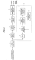
- Fig. 8 is a block diagram of the conventional (pulsive) noise reduction apparatus disclosed in, for example, JP-A-63-87026.
- a detection signal outputted from an FM detection circuit 1 is supplied to a delay circuit 2 composed of a LPF (low pass filter) and delayed, and the output of the delay circuit 2 is supplied to a stereo demodulation circuit 5 through a gate circuit 3, and a level hold circuit 4.
- the detection signal is supplied to a HPF (high pass filter) 6, and a noise component signal passed through the HPF 6 is amplified by a noise amplifier 7, and supplied to a noise detection circuit 8.
- the noise detection circuit 8 is composed of a rectifier circuit to rectify the output signal of the noise amplifier 7, and a noise detection output is obtained thereby.
- This noise detection output is supplied to a waveform shaping circuit 9 and an integration circuit 10.
- a noise detection means 11 is structured by including the HPF 6, noise amplifier 7, noise detection circuit 8, waveform shaping circuit 9 and integration circuit 10.
- the waveform shaping circuit 9 transforms the noise detection output into a pulse having a pulse width of a predetermined time period width, and supplied to the gate circuit 3.
- the gate circuit 3 is driven by a pulse supplied from the waveform shaping circuit 9 to the gate circuit 3 and comes to a signal cut out condition, and at the time of the signal cut out condition, a delay output level before the signal cut out is held by the level hold circuit 4, and supplied to the stereo demodulation circuit 5.
- the generation of a spike noise by the sudden change of the potential of the demodulation signal due to the pulsive noise is prevented.
- the gate circuit 3 and the level hold circuit 4 become the signal through condition (through).
- the integration circuit 10 smoothes the noise detection output and obtains a DC signal corresponding to the noise level, and supplies the output of the integration circuit 10 to the noise amplifier 7 (feedback), and thereby, an AGC loop is formed.
- the delay circuit 2 is provided to make up for a time period from the time when the pulsive noise is supplied to the HPF 6 to the time when the gate circuit 3 is made to be in the cut out condition.
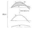
- the Lch (left channel) signal and Rch (right channel) signal are inputted in the form which is balancedly modulated with the frequency of 38 kHz around (Lch + Rch) /2, the LCh signal and the Rch signal can be separately picked out by the time division with, for example, 38 kHz.
- Fig. 10A a waveform in the case where a correction error in which a low frequency signal is corrected to a correction period, becomes maximum, is shown.
- ⁇ mark is a value in which ⁇ mark is corrected, and the difference between ⁇ mark and ⁇ mark shows the correction error.
- Fig. 10B a waveform when a high freqency signal is corrected to a correction period, is shown.
- O mark shows a value in which ⁇ mark is corrected.
- the difference between ⁇ mark and ⁇ mark shows the correction error.
- Fig. 10B when each of correction errors is observed, Fig. 10B is larger.. That is, it is found that the relative relationship of the time width of the frequency to the correction period is very important, and even when a signal of a high frequency component is corrected, the error is large. Accordingly, even when the correction is conducted on the signal of the high frequency component, the correction error is heard as a noise.
- the pulse width of the pulsive noise is several tens ⁇ s to several hundreds ⁇ s
- a composite signal has, as shown in Fig. 9, a component which is balancedly modulated with 38 kHz, and because the period of the signal is shorter than that of the pulsive noise, the correction error as shown in Fig. 10B, is generated.
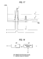
- FIG. 19A A case where the pulsive noise is generated in a time period of ta of the demodulated signal in the FM demodulator 1, is shown in Fig. 19A.
- a value of A in Fig. 19A is held in a period of ta in the level hold circuit 4.
- FIG. 19B A Lch waveform obtained by the stereo demodulation of this corrected signal is shown in Fig. 19B, and a Rch waveform is shown in Fig. 19C.
- the object of the present invention is to obtain a noise reduction apparatus by which the correction error can be reduced even for the signal in which many high frequency components are included, and the noise suppression ability is increased.
- a noise reduction apparatus is provided with: a noise detection means for detecting a noise included in a demodulated audio signal; the first correction means for outputting a correction signal for correcting the noise according to a signal value existing just before and just after a predetermined period including a generation time point of the noise in the demodulated audio signal which is detected by the noise detection means; the second correction means for outputting the correction signal for correcting the noise according to a plurality of signal values respectively existing before and after the predetermined period including the generation time point of the noise in the demodulated audio signal which is detected by the noise detection means; a high band level detection means for detecting the level of a high band component of the audio signal; and a selection means for selecting either one of the first or the second correction means according to the output of the high band level detection means.
- the noise reduction apparatus is structured such that the first correction means outputs a low pass filter output of a signal value obtained from a linear interpolation of 2 signal values existing just before and just after a predetermined period including a generation time point of the noise, as a correction signal.
- the noise reduction apparatus is structured such that the second correction means outputs a low pass filter output of the signal value obtained from the linear interpolation of 2 average signal values obtained by averaging a plurality of signal values existing before and after a predetermined period including the generation time point of the noise, corresponding to each of before and after the generation of the noise, as the correction signal.
- the noise reduction apparatus is structured such that a level detection means for detecting the whole band level in the demodulated audio signal is further provided, and a selection means is operated according to a relationship between a ratio of the level output of a high band level detection means to the level output of the level detection means, -and a predetermined value.
- the noise reduction apparatus is structured such that the detection sensitivity of the noise detection means is changeable corresponding to the output level of the high band level detection means.
- the noise reduction apparatus is structured such that the selection means is operated according to the level of an addition signal and the level of a subtraction signal between the right channel signal and the left channel signal constituting the audio signal.
- An audio output apparatus is provided with the noise reduction apparatus according to any one of the first aspect to the sixth aspect of the invention.
- the object of the present invention is to obtain a noise reduction apparatus by which the correction error is not influenced by the other channel, and an audio apparatus.
- a noise detection means for detecting the noise included in a demodulation signal having the information corresponding to audio signals of a plurality of channels from the demodulation signals; an audio signal demodulation means for demodulating and outputting the audio signals corresponding to each of the plurality of channels from the information corresponding to the audio signals included in the demodulation signals; and a correction means which can correct independently for each audio signal outputted from the audio signal demodulation means according to the output of the noise detection means, are provided.
- the noise detection means is structured in such a manner that the apparatus conducts the noise detection so that, for each predetermined period which alternates between a plurality of channels, a portion of the period respectively overlaps with each other.
- the apparatus is structured in such a manner that, according to the output of the noise detection means, a generation condition of the noise is detected, and corresponding to the detected result, the detection sensitivity of the noise detection means is controlled.
- the audio apparatus is structured by including any one of the above noise reduction apparatus.
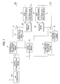
- Fig. 1 is a block diagram showing the structure of the embodiment 1.
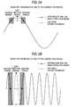
- Figs. 2A and 2B are views showing a corrected waveform of a noise reduction apparatus of the embodiment 1.
- Figs. 3A and 3B are block diagrams showing the structure of a level detection means after the stereo demodulation of the noise reduction apparatus of the embodiment 1.
- Fig. 4 is a block diagram showing the structure of the embodiment 2.
- Figs. 5A and 5B are block diagrams explaining a correction operation of the embodiment 2.
- Fig. 6 is a block diagram showing the structure of a noise detection means of the embodiment 2.
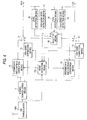
- Fig. 7 is a block diagram showing the structure of the embodiment 3.
- Fig. 8 is a block diagram showing the structure of the conventional noise reduction apparatus.
- Fig. 9 is a view showing the FM stereo demodulation waveform.
- Figs. 10A and 10B are an example of a noise correction waveform.
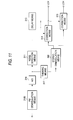
- Fig. 11 is a block diagram showing the structure of a noise reduction apparatus.
- Fig. 12 is an illustration for explaining the spectrum of an FM demodulation signal.
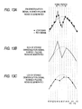
- Figs. 13A to 13C are illustration for explaining the stereo demodulation signal of the signal in which the pulsive noise is generated.
- Fig. 14 is a block diagram showing the structure of a noise detection means.
- Figs. 15A and 15B are illustration for explaining the output of an absolute value circuit.
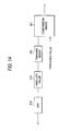
- Fig. 16 is a block diagram for explaining the structure for controlling the pulse density.
- Fig. 17 is an illustration for explaining the detection of a pulsive noise.
- Fig. 18 is a block diagram showing the structure of a pulse density detection means.
- Figs. 19A to 19C are illustration for explaining the waveform when the signal in which the pulsive noise is generated, is stereo-demodulated by the conventional apparatus.
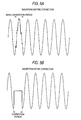
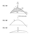
- Figs. 20A to 20C are illustration for explaining the waveform in a simple type of a high band correction means.
- An embodiment having the structure by which a great effect can be displayed for the noise reduction, when being applied for, for example, a car audio device such as a car radio, an audio output apparatus such as a car video device of a car mounting type television, or an image sound apparatus including this audio output apparatus, will be described below.
- Fig. 1 is a block structural diagram of a noise reduction apparatus of the embodiment 1 of the present invention.
- Numeral 1000 is an FM demodulation means for demodulating an FM signal from a received broadcasting wave
- numeral 5 is a stereo demodulation means
- numeral 12 is an intermediate and low band correction means for intermediate and low band signals of an Rch of the stereo demodulation means
- numeral 13 is a high band correction means for a high band signal of the Rch of the stereo demodulation means
- numeral 21 is a switch for switching output signals of the high band correction means 13 and intermediate and low band correction means 12
- numeral 14 is an intermediate and low band correction means for intermediate and low band signals of an Lch of the stereo demodulation means 5 (herein, the intermediate and low band correction means 12 and 14 are the first correction means provided respectively corresponding to the Rch and Lch).
- Numeral 15 is a high band correction means for the high band signal of the Lch of the stereo demodulation means
- numeral 22 is a switch for switching the outputs of the high band correction means 15 and the intermediate and low band correction means 14
- numeral 16 is a level detection means for detecting the level (envelope) of the output signal of the switch 21
- numeral 17 is a high band level detection means for detecting the high band component of the output signal of the switch 21, (herein, the high band correction means 13 and 15 are the second correction means provided respectively corresponding to the Rch and Lch).
- Numeral 18 is a level detection means for detecting the level of the output signal of the switch 22
- numeral 19 is a high band level detection means for detecting the high band component of the output signal of the switch
- numeral 200 is a selection means for controlling the switch 21 corresponding to each output level of the level detection means 16 and the high band level detection means 17
- numeral 201 is a selection means for controlling the switch 22 corresponding to each output level of the level detection means 18 and the high band level detection means 19.
- the broadcasting signal received by the attached antenna enters into the FM demodulator 1000, and the FM demodulation signal is outputted by the FM demodulator 1000.
- This FM demodulation signal is inputted into the respective stereo demodulation circuit 5 and noise detection means 110, and the following processing, which will be detailed below, is conducted.
- the noise detection means 110 detects the pulsive noise, for example, in the same manner as in the noise detection means 11 in the conventional apparatus.
- a gate signal of the high level (H level) is outputted, in the period in which the pulsive noise is detected
- the gate signal of the low level (L level) is outputted, in the period in which the pulsive noise is not detected, and these gate signal outputs are inputted into the high band correction means 13, intermediate and low band correction means 12, the high band correction means 15, and intermediate and low band correction means 14.
- each of correction means 12 - 15 corrects the input signal (the output from the stereo demodulation means 5) in the period in which the gate signal is the H level, and the input signal is outputted as it is, in the period of the L level. (Correction by the values before and after the correction period)
- the intermediate and low band correction means 12 and 14 linear interpolate (the signal outputted by the linear interpolation is called the correction signal) the signal in the period in which the noise is generated, by using the values before and after the correction period.
- the correction signal is outputted through the low pass filter.
- ⁇ mark shows the level to be originally obtained when the noise is not generated, and in this example, it corresponds to a point at which the correction error becomes the maximum, and ⁇ mark shows the correction value (the correction value by the intermediate and low band correction means 12).
- Fig. 2A shows a case where the wavelength of the output signal of the stereo demodulation means 5 is long to the correction period (that is, the frequency is low to the correction period), and the level difference (differential value)between ⁇ mark and ⁇ mark is small, the error by the correction is very small or slight to the amplitude of the signal waveform.
- the correction signal for correcting the noise according to the signal values which exist just before and just after a predetermined period including the generation time point of the noise is outputted (in the first correction means in the description of each embodiment below, the same operation is conducted except for the specific exception).
- Fig. 2B shows a case where the wavelength of the output signal of the stereo demodulation means 5 is short to the correction period (that is, the frequency is high to the correction period), and the level difference (differential value)between ⁇ mark and ⁇ mark is large, and the error by the correction is large to the amplitude of the signal waveform.
- the high band correction means 13 and 15 conduct the averaging processing before and after the correction period, ( ⁇ mark is the average value in the average period), and by using these two average values (the average signal value as the correction signal), the linear interpolation is conducted. Incidentally, this correction signal (average signal value) is outputted through the low pass filter.
- the average period herein means a predetermined period before and after the noise period, and the average value of the signal level in the period is obtained according to a plurality of signal values included in the period.
- Fig. 2A shows a case where the wavelength of the output signal of the stereo demodulation means 5 is long to the correction period (that is, the frequency is low to the correction period), and in the level difference from ⁇ mark, ⁇ mark is smaller than ⁇ mark.
- Fig. 2A shows a case where the wavelength of the output signal of the stereo demodulation means 5 is short to the correction period (that is, the frequency is high to the correction period), and in the level difference from ⁇ mark, ⁇ mark is smaller than ⁇ mark.
- the correction (interpolation processing) is conducted by using the intermediate and low band correction means 12 and 14, and when the wavelength of the signal waveform is short to the correction period (that is, the frequency of the signal waveform is high to the correction period), the correction (interpolation processing) is conducted by using the high band correction means 13 and 15.
- the correction signal for correcting the noise according to a plurality of signal values which exist just after a predetermined period including the generation time point of the noise is outputted (in the second correction means in the description of each embodiment below, the same operation is conducted except for the specific exception).
- the level detection means 16 the level of the signal corrected by using the high band correction means 12 or the intermediate and low band correction means 13, is detected (envelope detection).
- the level detection means 16 in this case can be realized by adopting the structure, for example, as in Fig. 3A.
- the DC component is not included in the output of the switch 21.
- numeral 23 is an absolute value circuit
- numeral 24 is a low pass filter (LPF).
- LPF 24 is a low pass filter
- the level detector 18, for the high band correction means 15 or the intermediate and low band correction means 14 and the switch 22, the structure to which the Rch corresponds, is respectively adopted, and for also the structure of the level detector 18, the same structure as shown in Fig. 3A is adopted, and its operation is also the same.
- the high band level detection means will be described (hereinafter, for simple understanding, initially, the structure according to the series of Rch will be described) .
- the high band level detection means 17 detects the level of the signal which is corrected by using the high band correction means 12 and intermediate and low band correction means 13 (envelope detection).
- the high band level detection means 17 in this case can be realized by adopting the structure, for example, as shown in Fig. 3B.
- a DC component is not included in the output of the switch 21.
- numeral 25 is a high pass filter (HPF)
- numeral 26 is an absolute value circuit
- numeral 27 is a low pass filter (LPF) . Initially, in the HPF 25, the low band component of the output signal outputted from the switch 21 is removed, and the high band component is obtained.
- HPF high pass filter
- LPF low pass filter
- the absolute value circuit 26 the absolute value of the output signal of the HPF 25 is obtained.
- the high band component is removed by the LPF 27.
- the output signal of the LPF 27 is outputted as an envelope of the high band component of the signal outputted from the switch 21.
- the structure to which the Rch corresponds is respectively adopted, and for also the structure of the high band level detector 19, the same structure as shown in Fig. 3B is adopted, and its operation is also the same.
- the output signal VH form the high band level detection means 17 and the output signal VA from the level detection means 16 are inputted.
- the selection means 200 connect the output side of the Rch to the intermediate and low band correction means 12 by the switch 21, or the selection means 201 connects the output side of the Lch to the intermediate and low band correction means 14 by the switch 22.
- the selection means 200 connect the output side of the Rch to the high band correction means 13 by the switch 21, or the selection means 201 connects the output side of the Lch to the high band correction means 15 by the switch 22.
- the correction means is selected corresponding to the result of the comparison of the ratio of the level VH of the high band component (the envelope of the high band component) in the FM stereo demodulation signal to the level VA of the whole band (the envelope of the whole band), with the predetermined value, the correction error can be decreased.
- the above described these processing may also be conducted by the digital signal processing by using the DSP (Digital Signal Processor) after the output signal of the FM detection circuit 1 is A/D converted (Analog to Digital conversion).
- DSP Digital Signal Processor
- the processing for the correction may be neglected.
- the high band level detection means 17 or 19 a case in which the HPF 25 shown in Fig. 3 is used, is described, however, because, in the stereo demodulated signal, for example, the component higher than 15 kHz is basically unused, the BPF by which the component higher than 15 kHz can be removed, may be used.
- the signal in the noise period is linearly interpolated, further, passes through the LPF, and after the high band component of the correction error is suppressed, it may be replaced with the signal (noise) in the noise period.
- an input signal (Fig. 20A) of the high band correction means 13 and 15 is input into an LPF, and holds an output signal level (P of Fig. 20B) of LPF immediately before a pulse noise generation so as to correct (Fig. 20C).
- the operation of the selection means is determined according to the relationship between the rate (VH/VA) of the VH (the level output of the high band level detection means) to the VA (the level output of the level detection means), and a predetermined value, however, when the signal level of the VH is not extremely large, it is needless to explain that the operation of the selection means may be determined according to the relationship between only the VH and the predetermined value.
- Fig. 4 is a block structural diagram of the noise reduction apparatus of the embodiment 2 of the present invention.
- Numeral 5 is a stereo demodulation means
- numeral 12 is an intermediate and low band correction means for conduct the correction on the intermediate and low band signal of the Rch of the stereo demodulation means
- numeral 13 is a high band correction means for conduct the correction on the high band signal of the Rch of the stereo demodulation means 5.
- Numeral 21 is a switch to switch the output signals of the high band correction means 13 and intermediate and low band correction means 12
- numeral 14 is an intermediate and low band correction means for an intermediate and low band signal of the Lch of the stereo demodulation means 5
- numeral 15 is a high band correction means for a high band signal of the Lch of the stereo demodulation means 5.
- Numeral 22 is a switch to switch the output signals of the high band correction means 15 and intermediate and low band correction means 14, numeral 16 is a level detection means of the output signal of the switch 21, and numeral 17 is a high band level detection means for detecting the high band component of the output signal of the switch 21.
- Numeral 18 is a level detection means for detecting the level of the output signal of the switch 22, and numeral 19 is a high band level detection means for detecting the high band component of the output signal of the switch 22.
- Numeral 28 is a selection means for controlling the switches 21 and 22 corresponding to each output level of the high band level detection means 17 and 19, and the level detection means 16 and 18, and numeral 111 is a noise-detection means for adjusting the sensitivity of the noise detection corresponding to the output from the high band level detection means 17 and 19.
- a small pulsive noise is corrected.
- a noise having the amplitude up to 50 % of the amplitude level of the signal waveform is called a small pulsive noise.
- Fig. 5A shows an example of a waveform before the small pulsive noise is corrected
- Fig. 5B shows an example of a waveform after the small pulsive noise is corrected.
- the level difference (error) is larger in the waveform after the correction than in the waveform before correction (the waveform largely deforms from the original signal waveform.
- the waveform is largely deformed in the portion which is corrected from the original sinusoidal wave), there is a case where the noise is rather larger by the correction.
- the high frequency signal is corrected, because the correction error becomes large, this tendency becomes large.
- FIG. 6 An example of the detection means 111 by which the above operations can re realized, is shown in Fig. 6.
- the operations of the HPF 6, noise amplifier 7, waveform shaping circuit 9, and integration circuit 10, which are shown in Fig. 6, are the same as the operations in the conventional apparatus.
- the output of the integration circuit 10 and the outputs of the high band level detection means 17 and 19, are given weight through a weight section 29 and a weight section 30 (a coefficient is respectively multiplied, of course, a case where the coefficient is 1, is included), and after that, each output is added, and the addition result is inputted into the noise amplifier 7 as the control signal.
- the gain of the noise amplifier 7 in the case where the outputs of the high band level detection means 17 and 19 are 0, acts so that the average level of the output signal of the noise detection circuit 8 is kept constant.
- the average level of the output signal of the noise detection circuit 8 is smaller than the threshold value of the waveform shaping circuit 9.
- the gain of the noise amplifier 7 does not change, when the pulsive noise is added to the noise amplifier 7, the output of the noise-detection circuit 8 is larger than the threshold value of the waveform shaping circuit 9, and the waveform shaping circuit 9 outputs the H level and the pulsive noise is detected.
- the pulsive noise smaller than the difference between the average value of the output of the noise detection circuit 8 and the threshold value of the waveform shaping circuit 9 is generated, it is not detected. Accordingly, when up to the small pulsive noise is detected, the difference between the average value of the output of the noise detection circuit 8 and the threshold value of the waveform shaping circuit 9 is made small, and when the small pulsive noise is not detected, the difference between the average value of the output of the noise detection circuit 8 and the threshold value of the waveform shaping circuit 9 may be made large.
- the average value of the output signal of the noise detection circuit 8 becomes small, and because the difference to the threshold value of the waveform shaping circuit 9 becomes large, the small pulsive noise is not detected.
- the detection sensitivity of the pulsive noise is lowered (that is, the detection sensitivity is changeable corresponding to the output level of the high band level detection means), the correction error due to the correction of the small pulsive noise is decreased.
- these processing may A/D convert the output signal of the FM detection circuit 1, and the processing after that may be conducted by using the digital signal processing technique such as the DSP.
- the processing for the correction in the correction means which is not selected can be neglected.
- Fig. 7 is a block structural diagram of the noise reduction apparatus of the embodiment 3 of the present invention.
- numeral 112 is a noise detection means for detecting the pulsive noise from the output of the FM detection circuit 1
- numeral 120 is an intermediate and low band correction means for conducting the correction on the intermediate and low band signals when there are many intermediate and low band components
- numeral 130 is a high band correction means for conducting the correction on the high band signals when there are many high band components
- numeral 21 is a switch to switch the outputs of the intermediate and low band correction means 120 and the high band correction means 130.
- Numeral 5 is a stereo demodulation means connected to the output signal of the switch 21, numeral 160 is a level detection means for detecting the level of the Lch signal of the stereo demodulation means 5, numeral 170 is a high band level detection means for detecting the high band signal level in the Lch signals of the stereo demodulation means 5, and numeral 180 is a level detection means for detecting the signal level of the Rch signal of the stereo demodulation means 5.
- Numeral 190 is a high band level detection means for detecting the high band signal level in the Rch signal of the stereo demodulation means
- numeral 300 is an L - R level detection means for detecting the level of the L - R component which is the difference between the signal level of the Lch signal and the signal level of the Rch signal (the level of the subtraction signal. incidentally, R - L component may be allowable)
- numeral 301 is an L + R level detection means for detecting the level of the L + R component which is the sum of the signal level of the Lch signal and the signal level of the Rch signal (the level of the addition signal).
- Numeral 400 is a selection means for switching the switch 21 corresponding to each of outputs of the level detection means 160 and 180, high band detection means 170 and 190, and L - R level detection means 300.
- the noise detection means 112 detects the pulsive noise, for example, in the same manner as the detection means 11 in the conventional apparatus.
- the output signal of the noise detection means 112 outputs the high level (H level) in the period in which the pulsive noise is detected, and the low level (L level) in the period in which the pulsive noise is not detected, and it is inputted into the high band correction means 130 and the intermediate and low band correction means 120.
- the correction means 120 and 130 correct the signals in the period in which the gate signal is the H level.
- the output signal to be corrected of the FM detection circuit 1 is composed of the L + R component of 0 to 15 kHz, L - R component which is AM modulated with 38 kHz in the band of 23 to 53 kHz, and the pilot signal of 19 kHz.
- the correction corresponding to the pulsive noise with the width of several tens ⁇ s is conducted, there is also a case in which the pulsive noises of several wavelengths exist in the correction period, and when the pre-value holding, or linear interpolation is simply conducted, there is a case in which the correction error rather becomes large.
- the high band correction means 130 is used, and the error due to the correction is made small.
- the correction error can be made small.
- the selection means 400 operates in such a manner that the switch 21 is connected to the intermediate and low band correction means 120.
- the output signal of the L - R level detection means 300 is obtained from the output in which , for example, the absolute value of the difference between the stereo demodulated Lch and Rch is inputted into the LPF.
- the output signal of the L + R level detection means 301 is obtained from the output of the LPF in which , for example, the absolute value of the sum of the Lch signal and Rch signal which are FM demodulated into the stereo, is an input.
- the above described these processing may be conducted as follows: the output signal of the FM detection circuit 1 is A/D converted, and the subsequent processing is conducted by using the digital signal processing technique such as the DSP.
- the processing is conducted on the signal after the stereo FM demodulation, and the processed signal is inputted into the selection means 400, however, the signal level of the high band in the composite signal in which the output signal of the switch 21 is corrected, is detected, and when it is small, because the L - R component is small, and further, the high band component of the signal which is FM demodulated into the stereo is also small, the switch 21 may be connected to the intermediate and low band correction means 120.
- the apparatus is provided with: a noise detection means for detecting a noise included in a demodulated audio signal; the first correction means for outputting a correction signal for correcting the noise according to a signal value existing just before and just after a predetermined period including a generation time point of the noise in the demodulated audio signal which is detected by the noise detection means; the second correction means for outputting the correction signal for correcting the noise according to a plurality of signal values respectively existing before and after the predetermined period including the generation time point of the noise in the demodulated audio signal which is detected by the noise detection means; a high band level detection means for detecting the level of a high band component of the audio signal; and a selection means for selecting either one of the first or the second correction means according to the output of the high band level detection means, thereby, even when the high frequency components are included in the audio signal, the high frequency components are detected, and when the rate of the high frequency components is large, because the correction in which the error is few to the
- the first correction means is structured such that it outputs a low pass filter output of a signal value obtained from a linear interpolation of 2 signal values existing just before and just after a predetermined period including a generation time point of the noise, as a correction signal, thereby, the correction error when the rate of the low frequency components is large, can be decreased.
- the second correction means is structured such that it outputs a low pass filter output of the signal value obtained from the linear interpolation of 2 average signal values obtained by averaging a plurality of signal values existing before and after a predetermined period including the generation time point of the noise, corresponding to each of before and after of the generation of the noise, as the correction signal, thereby, the signal correction when the rate of the high frequency components is large, can be accurately corrected, and the correction error can be decreased.
- the apparatus is structured such that a level detection means for detecting the whole band in the demodulated audio signal is further provided, and a selection means is operated according to a relationship between a ratio of the level output of a high band level detection means to the level output of the level detection means, and a predetermined value, thereby, even when the output from the high band level detection means is large, the noise can be surely caught.
- the noise detection means is structured such that the detection sensitivity of the noise detection means is changeable corresponding to the output level of the high band level detection means, thereby, the generation of large error due to the correction in the case where the low level noise is included, can be prevented.
- the apparatus is structured such that the selection means is operated according to the level of an addition signal and the level of a subtraction signal between the right channel signal and the left channel signal constituting the audio signal, thereby, the correction suited to the received signal can be conducted.
- an audio output apparatus because the apparatus is provided with the noise reduction apparatus according to the first aspect to the sixth aspect, thereby, the audio output apparatus by which, even when the noise is included, the optimum correction to the noise is conducted, and the high quality audio output can be obtained, can be realized.
- An embodiment having the structure by which a great effect can be displayed for the noise reduction, when being applied for, for example, a car audio device such as a car radio, an audio output apparatus such as a car video device of a car mounting type television, or an image sound apparatus including this audio output apparatus, will be described below.
- Fig. 11 is a block structural diagram of the noise reduction apparatus of the embodiment 4 of the present invention.
- numeral 2100 is an FM demodulation means for demodulating an FM signal from a received broadcasting wave
- numeral 305 is a stereo demodulation means
- numeral 313 is a delay means for adjusting a timing between an output signal from the noise detection means and an output signal from the stereo demodulation means 305
- numeral 314 is an Lch correction means
- numeral 315 is an Rch correction means
- numeral 316 is an A/D converter means
- numeral 317 is a thinning means for thinning out the data of the A/D converter means 316.
- the received broadcast signal is FM-demodulated by the FM demodulator means 2100, and the demodulated signal (demodulation signal) is converted into a digital data by the A/D converter means 316.
- the signal component up to 53 kHz is included.
- the thinning means 317 lowers the sampling frequency of the output signal from the A/D converter 316, to the degree which at least satisfies the Nyquist frequency (106 kHz) of 53 kHz which is the highest frequency of the FM demodulation signal f(t), as described above, and outputs to the stereo demodulation means 305.
- each of signals of Lch and Rch can be taken out in such a manner that the signal of the Lch can be taken out, when the sampling is conducted at the timing of every 4n, and the signal of Rch can be taken out, when the sampling is conducted at the timing of every 4n in which 2n is shifted from the timing of every 4n.
- Fig. 13 the waveform in which the pulsive noise as the noise, mixes in the output signal of the FM demodulation means 301 in the case where the waveforms of the Lch and Rch are essentially the same, is shown.
- Fig. 13A shows the output from the FM demodulation means 301, and • is a sample value of the Lch, o is the sample value of Rch, and ⁇ is the sample value of the other timings.
- the sample value at the timing of the above ⁇ mark is a value which is sampled for basically detecting the generation position of the noise or the generation time, and is obtained by, for example, the sample frequency in which the sample period is such as 60 kHz - 100 kHz, which is higher than 53 kHz.
- Fig. 13B shows the Rch signal after the stereo demodulation
- Fig. 13C shows the Lch signal after the stereo demodulation.
- the condition that the mixed pulsive noise is generated in which the pulsive noise for 2 sampling is mixed in the Lch and the pulsive noise for 2 sampling is mixed in the Rch, is shown.
- the correction is conducted at the independent timing, that is, the correction means 315 corrects the Rch signal at t2 and t8, and the correction means 314 corrects the Rch signal at t3 and t9.
- the correction in this case is conducted in such a manner that, when so called front hold type interpolation by which, for example, the t2 value is corrected to t4 and t6 values (Rch), or the t3 value is corrected to t5 and t7 values (Lch), or so called linear interpolation type interpolation by which the correction value is the value (Rch) corresponding to each time of t4 and t6 when the linear interpolation is conducted at the t2 value and the t8 value, or the correction value is the value (Lch) corresponding to each time of t5 and t7 when the linear interpolation is conducted at the t3 value and the t9 value, is adopted, the signal is corrected.
- the noise detection means 311 as the noise detection means will be described.
- the noise detection means 311 the pulsive noise is detected by using the higher frequency signal than each sampling frequency of the Lch and Rch (thereby, the resolution of the noise detection is determined.)
- the output signal (noise detection signal) from the noise detection means 311 outputs the gate signal of the H level in a period in which the noise is detected, and the L level in a period in which the noise is not detected.
- the period in which the noise generates is from t4 to t7, and in this period, the detection means 311 outputs the H level, and the sampling frequency of the output data in the noise detection means 311 in this case, is not smaller than 2 times of the sampling frequency of the Lch signal or Rch signal.
- the delay is generated in the inputted signal into the stereo demodulation means 305.
- the delay is also generated in the correction means 314 and 315.
- the delay means 313 the output signal from the noise detection means 311 is delayed, and the time point (position) at which the pulsive noise in the output signal of the stereo demodulation means 305 in which the delay is generated, is generated, is timed with the noise detection signal outputted from the noise detection means 311.
- the noise is detected from the FM stereo demodulated signal, and because a signal portion in which the pulsive noise of the FM stereo demodulated signal is mixed (generated) is corrected independently in the left and right, (viewed from respective channels), the amplitude of the signal of the other channel does not influence on the correction result, and the suppression effect of the noise is increased.
- the noise detection can be conducted under the condition that the noise component is not lost.
- Fig. 14 shows the noise detection means 311 by the digital processing.
- the component of the high frequency is extracted by the HPF 318 from the output of the A/D converter 316.
- the output level of the HPF 318 is increased.
- the absolute value of the output signal of the HPF 318 is calculated in the absolute value circuit 319.
- o ⁇ shows the sample value of the Lch
- o shows the sample value of the Rch
- • shows the other sample value.
- Fig. 15A the maximum values st1, st2, and st3 of the t1, t2, and t3 periods are outputted as the noise levels of L1, R1 and L2.
- the pulse width of the pulsive noise included in the output signal of the A/D converter 316 spreads due to the filter processing by, for example, the FIR filter in the thinning means 317, and the stereo demodulator 305. Accordingly, even when the noise is slightly generated in L2, there is a case in which it becomes as if the noise is generated in the signal after the stereo demodulation.
- the thinning means 320 makes the period to detect the noise of L1, R1, and L2 overlap with each other as t1', t2' and t3' shown in Fig. 15B, and outputs the maximum values of the respective periods of st1', st2', and st3' as the noise levels of L1, R1 and L2.
- the comparison means 321 judges that the pulsive noise is generated at R1 and L2.
- the period in which the sample noise such as L2 is detected is overlapped, and can be detected as the noise exists therein, wherein the large noise exists in the near sample of L2, and after the stereo demodulation, the influence of the noise is exerted on L2.
- the noise detection means is structured in such a manner that, for each predetermined period which alternates among a plurality of channels, a portion of the period is made to overlap each other, and the noise is detected, thereby, the noise detection means can more exactly detect the noise.
- Fig. 15B the detection of the noise by which 1 sample is made to overlap the other, and the influence is exerted on the subsequent signal, is described, however, the overlap of the sample may be carried out on a plurality of points, and it may be determined by considering the pass band characteristic of the filter processing by, for example, the FIR filter (specifically, the LPF included in these structures) in the thinning means 317, or the stereo demodulator 305, or the amplitude level.
- the FIR filter specifically, the LPF included in these structures
- the detection sensitivity of the pulsive noise may be controlled so that the pulse width of the detected pulsive noise is not larger than a predetermined value (predetermined width).
- the structure by which the density of the pulsive noise to be detected (herein, sometimes simply called pulse density) can be controlled, is shown in Fig. 16 (incidentally, in the structure shown in Fig. 16, the output of the thinning means 320 of the noise detection means 311 shown in Fig. 14 is changed to the input.
- the noise detection means 311 is structured by including the structure shown in Fig. 14 and the structure shown in Fig. 16.)
- the output signal of the LPF 323 corresponds to the level of the continuously generating noise such as the background noise (due to the noises of the devices or the thermal noise).
- the adder 324 adds the output signal of the LPF 323 and the output of the pulse density detection means 325, and when the output of thinning means 320 is larger than the output signal of the adder 324, the comparison means 321 judges that the pulsive noise exists.
- the output signal of the comparison means 321 is inputted into the pulse density detection means 325, and when the pulse density of the inputting signal is higher than a predetermined value, the output signal is made larger and inputted into the adder 324. Thereby, the output signal of the adder 324 becomes large. That is, by the pulse density detection means 325, the feedback loop is structured between the output of the comparison means 321 and the adder 324.
- Fig. 17 is a view showing an example of the operation by the structure shown in Fig. 16.
- the output of the adder 324 when the pulse density is small is shown by the waveform b.
- the output of the adder 324 when the pulse density is increased and the output of the pulse density detection means 325 is inputted into the adder 324 is shown by the waveform a (incidentally, in the drawing, the waveforms a and b are linearly shown for the simplification, but, generally these are waveforms).
- the waveform c An example of the output from the thinning means 320 is shown by the waveform c.
- the waveform b is inputted into the comparison means 321 as the threshold value 321.
- the comparison means 321 outputs the H level as the pulsive noise is generated in a portion of the waveform c whose value is larger than the waveform b inputted as the threshold value. Accordingly, in the example shown in the drawing, it is shown that the pulsive noises of 2 portions are detected as shown in the waveform d.
- the comparison means 321 outputs the H level as the pulsive noise is generated in a portion of the waveform c whose value is larger than the waveform a inputted as the threshold value. Accordingly, in the example shown in the drawing, the small pulsive noise as shown in the waveform e is not detected.
- the peak value of the output signal of the comparison means 321 shown in Fig. 16 is constant, and inputted into the LPF 326, and the DC component DO is taken out.
- the DC component DO in this case is proportional to the pulse density.
- the calculation means 327 conducts the following processing, in which the desired value of the pulsive noise to be detected is D1, and the output signal is the feedback amount Nc (A is a feedback gain, and is a fixed value herein) .
- Nc Nc + A ⁇ (D0 - D1)
- the detection sensitivity of the noise detection means is controlled according to the density of the pulsive noise (noise) as the generation condition of the noise, the lowering of the audio quality due to the excessive signal correction can be prevented.
- the above embodiment can be realized by using the DSP (Digital Signal Processor) using the digital signal processing technology, which needs no description here, and by using such the technology, the adaptability of the noise reduction processing which is adaptive to the reduction of the circuit structure and the nature of the noise, can be increased.
- DSP Digital Signal Processor
- the noise reduction apparatus is provided with: a noise detection means for detecting the noise included in a demodulation signal having the information corresponding to audio signals of a plurality of channels from the demodulation signals; an audio signal demodulation means for demodulating and outputting the audio signals corresponding to each of the plurality of channels from the information corresponding to the audio signals of the demodulation signals; and a correction means which can correct independently for each audio signal outputted from the audio signal demodulation means according to the output of the noise detection means, thereby, the influence of the other channel is not exerted in the correction of the signal of one channel, and further, because the detection of the noise is carried out in the demodulation signal, the noise detection can be carried out under the condition that the noise component is not lost.
- the noise detection means is structured such that the noise detection is conducted in such a manner that, for each predetermined period which alternates among a plurality of channels, a portion of the period respectively overlaps with each other, thereby, the noise reduction apparatus by which the more exact noise detection can be conducted, can be realized.
- the noise reduction apparatus is structured such that, according to the output of the noise detection means, a generation condition of the noise is detected, and corresponding to the detected result, the detection sensitivity of the noise detection means is controlled, thereby, the noise reduction apparatus by which the lowering of the audio quality due to the excessi-ve signal correction can be prevented, can be realized.
- the audio output apparatus is structured by including any one of the above noise reduction apparatus, thereby, even when the noise is included, an audio output apparatus by which the audio quality is not lowered, can be obtained.
Landscapes
- Engineering & Computer Science (AREA)
- Signal Processing (AREA)
- Computer Networks & Wireless Communication (AREA)
- Stereo-Broadcasting Methods (AREA)
- Noise Elimination (AREA)
Applications Claiming Priority (4)
| Application Number | Priority Date | Filing Date | Title |
|---|---|---|---|
| JP20124599A JP3627577B2 (ja) | 1999-07-15 | 1999-07-15 | 雑音除去装置およびオーディオ出力装置 |
| JP20124699A JP3465638B2 (ja) | 1999-07-15 | 1999-07-15 | 雑音除去装置およびオーディオ出力装置 |
| JP20124599 | 1999-07-15 | ||
| JP20124699 | 1999-07-15 |
Publications (3)
| Publication Number | Publication Date |
|---|---|
| EP1069693A2 true EP1069693A2 (de) | 2001-01-17 |
| EP1069693A3 EP1069693A3 (de) | 2003-03-19 |
| EP1069693B1 EP1069693B1 (de) | 2004-10-13 |
Family
ID=26512682
Family Applications (1)
| Application Number | Title | Priority Date | Filing Date |
|---|---|---|---|
| EP00305982A Expired - Lifetime EP1069693B1 (de) | 1999-07-15 | 2000-07-14 | Vorrichtung zum Reduzieren von Rauschen |
Country Status (3)
| Country | Link |
|---|---|
| US (1) | US7551743B1 (de) |
| EP (1) | EP1069693B1 (de) |
| DE (1) | DE60014790T2 (de) |
Cited By (5)
| Publication number | Priority date | Publication date | Assignee | Title |
|---|---|---|---|---|
| WO2005053175A1 (en) * | 2003-11-21 | 2005-06-09 | Bae Systems Plc | Suppression of unwanted signal elements by sinusoidal amplitude windowing |
| US7269237B2 (en) * | 2001-07-13 | 2007-09-11 | Sanyo Electric Co., Ltd. | Noise canceller |
| CN101056110B (zh) * | 2006-04-13 | 2010-06-30 | 三洋电机株式会社 | 噪声消除器以及使用了该噪声消除器的am接收装置 |
| CN1758336B (zh) * | 2001-07-10 | 2010-08-18 | 编码技术股份公司 | 用于低比特率音频编码应用的高效可标度参数立体声编码 |
| US8929558B2 (en) | 2009-09-10 | 2015-01-06 | Dolby International Ab | Audio signal of an FM stereo radio receiver by using parametric stereo |
Families Citing this family (8)
| Publication number | Priority date | Publication date | Assignee | Title |
|---|---|---|---|---|
| JP2005286787A (ja) * | 2004-03-30 | 2005-10-13 | Sanyo Electric Co Ltd | ノイズ除去回路 |
| US7706542B2 (en) * | 2005-03-28 | 2010-04-27 | Pioneer Corporation | Noise removal device |
| JP5311831B2 (ja) * | 2008-01-11 | 2013-10-09 | 富士通株式会社 | 通信装置、ノイズキャンセラ、ノイズ除去方法およびノイズ除去プログラム |
| JP5059677B2 (ja) * | 2008-04-18 | 2012-10-24 | ルネサスエレクトロニクス株式会社 | ノイズ除去装置、及びノイズ除去方法 |
| US8577056B2 (en) | 2010-06-30 | 2013-11-05 | Intel Corporation | Limiting peak audio power in mobile devices |
| US8306493B2 (en) * | 2010-04-13 | 2012-11-06 | Newport Media, Inc. | Pilot based adaptation for FM radio receiver |
| US9588566B2 (en) * | 2011-09-07 | 2017-03-07 | Texas Instruments Incorporated | Programmable time delay and signal polarity improving transceiver signal-to-noise metric |
| EP3822933B1 (de) * | 2019-11-15 | 2025-06-25 | Carrier Corporation | Verfahren und system zur rauschunterdrückung |
Family Cites Families (19)
| Publication number | Priority date | Publication date | Assignee | Title |
|---|---|---|---|---|
| JPS5946457B2 (ja) * | 1978-11-30 | 1984-11-13 | 松下電器産業株式会社 | パルス性雑音抑圧回路 |
| US4416024A (en) * | 1979-12-17 | 1983-11-15 | Sanyo Electric Co., Inc. | Distortion reducing circuit in FM receiver |
| JPS59182641A (ja) | 1983-03-31 | 1984-10-17 | Victor Co Of Japan Ltd | Fm放送波の受信に際してのパルス性雑音の低減装置 |
| US4574390A (en) * | 1983-03-26 | 1986-03-04 | Victor Company Of Japan, Limited | Noise reduction for stereophonic FM signals by high-speed sampling and linear interpolation |
| US4727580A (en) * | 1986-04-23 | 1988-02-23 | Alpine Electronics, Inc. | Radio receiver |
| JPH0681064B2 (ja) | 1986-09-30 | 1994-10-12 | パイオニア株式会社 | Fm受信機におけるパルス性雑音除去装置 |
| JPH0750860B2 (ja) | 1988-03-07 | 1995-05-31 | パイオニア株式会社 | Fm受信機におけるパルス性雑音除去装置 |
| DE4030560C1 (de) * | 1990-09-27 | 1992-02-20 | Sanwa Seidlitz Gmbh, 3593 Edertal, De | |
| US5134719A (en) * | 1991-02-19 | 1992-07-28 | Mankovitz Roy J | Apparatus and methods for identifying broadcast audio program selections in an FM stereo broadcast system |
| US5432854A (en) * | 1993-02-25 | 1995-07-11 | Chrysler Corporation | Stereo FM receiver, noise control circuit therefor |
| US5363413A (en) * | 1993-05-20 | 1994-11-08 | Motorola, Inc. | Data decoder and method for use therein using a dynamically indexed channel state metric |
| CA2125220C (en) | 1993-06-08 | 2000-08-15 | Joji Kane | Noise suppressing apparatus capable of preventing deterioration in high frequency signal characteristic after noise suppression and in balanced signal transmitting system |
| JPH07231268A (ja) * | 1993-12-21 | 1995-08-29 | Toshiba Corp | Fmチューナにおけるパルスノイズキャンセラ |
| DE69535621T2 (de) * | 1994-09-02 | 2008-02-07 | Matsushita Electric Industrial Co., Ltd., Kadoma | Erkennungsvorrichtung zur Modulationsgrad |
| JP3681783B2 (ja) * | 1995-03-31 | 2005-08-10 | エルジー電子株式会社 | ダブルデッキビデオテープレコーダ |
| US6029053A (en) * | 1995-09-12 | 2000-02-22 | Lockheed Martin Corp. | Apparatus and method for reducing co-channel radio interference |
| JPH11186924A (ja) * | 1997-12-18 | 1999-07-09 | Mitsubishi Electric Corp | 雑音除去装置 |
| JP2954570B1 (ja) * | 1998-06-02 | 1999-09-27 | 株式会社次世代デジタルテレビジョン放送システム研究所 | 周波数選択性妨害訂正装置 |
| JP3675179B2 (ja) * | 1998-07-17 | 2005-07-27 | 三菱電機株式会社 | オーディオ信号の雑音除去装置 |
-
2000
- 2000-07-14 EP EP00305982A patent/EP1069693B1/de not_active Expired - Lifetime
- 2000-07-14 DE DE60014790T patent/DE60014790T2/de not_active Expired - Lifetime
- 2000-07-14 US US09/617,086 patent/US7551743B1/en not_active Expired - Fee Related
Cited By (8)
| Publication number | Priority date | Publication date | Assignee | Title |
|---|---|---|---|---|
| CN1758336B (zh) * | 2001-07-10 | 2010-08-18 | 编码技术股份公司 | 用于低比特率音频编码应用的高效可标度参数立体声编码 |
| US7269237B2 (en) * | 2001-07-13 | 2007-09-11 | Sanyo Electric Co., Ltd. | Noise canceller |
| WO2005053175A1 (en) * | 2003-11-21 | 2005-06-09 | Bae Systems Plc | Suppression of unwanted signal elements by sinusoidal amplitude windowing |
| AU2004310544B2 (en) * | 2003-11-21 | 2009-08-13 | Bae Systems Plc | Suppression of unwanted signal elements by sinusoidal amplitude windowing |
| US8085886B2 (en) | 2003-11-21 | 2011-12-27 | Bae Systems Plc | Supression of unwanted signal elements by sinusoidal amplitude windowing |
| CN101056110B (zh) * | 2006-04-13 | 2010-06-30 | 三洋电机株式会社 | 噪声消除器以及使用了该噪声消除器的am接收装置 |
| US8929558B2 (en) | 2009-09-10 | 2015-01-06 | Dolby International Ab | Audio signal of an FM stereo radio receiver by using parametric stereo |
| US9877132B2 (en) | 2009-09-10 | 2018-01-23 | Dolby International Ab | Audio signal of an FM stereo radio receiver by using parametric stereo |
Also Published As
| Publication number | Publication date |
|---|---|
| EP1069693B1 (de) | 2004-10-13 |
| US7551743B1 (en) | 2009-06-23 |
| EP1069693A3 (de) | 2003-03-19 |
| DE60014790D1 (de) | 2004-11-18 |
| DE60014790T2 (de) | 2006-02-09 |
Similar Documents
| Publication | Publication Date | Title |
|---|---|---|
| EP0253902B1 (de) | Rauschunterdrückungsvorrichtung und verfahren | |
| EP1069693A2 (de) | Vorrichtung zum Reduzieren von Rauschen und Audioausgangsvorrichtung | |
| EP0967738B1 (de) | Proportionaler Funk-Diversity-Empfänger | |
| US7756501B2 (en) | Multipass noise detecting apparatus and FM receiving apparatus | |
| EP1408616B1 (de) | Rauschlöscher | |
| JP2001237725A (ja) | 雑音除去装置 | |
| JP2000174644A (ja) | Fm信号受信中ノイズを低減する方法及びレシ―バ | |
| JP2004260528A (ja) | 音声放送受信装置および音声放送受信方法 | |
| US20080261549A1 (en) | Noise blanker circuit and method for removing noise and correcting a signal | |
| US20120142297A1 (en) | Receiver | |
| JP2809897B2 (ja) | テレビジョン信号受信装置および送信装置 | |
| JP2004056173A (ja) | ノイズ抑圧装置 | |
| JP3570378B2 (ja) | 雑音除去装置およびオーディオ装置 | |
| JP3465638B2 (ja) | 雑音除去装置およびオーディオ出力装置 | |
| JP3627577B2 (ja) | 雑音除去装置およびオーディオ出力装置 | |
| US7239710B2 (en) | Stereo radio receiver with noise suppression | |
| JP2003249863A (ja) | 受信機のトラッキングフィルタ制御方式 | |
| JP2005192060A (ja) | 自動利得制御装置 | |
| JP3120457B2 (ja) | ダイバーシティ方式のfm受信装置 | |
| JPH0789657B2 (ja) | 音声多重放送受信機 | |
| EP2290829A2 (de) | Tonsignalprozessor, FM-Empfänger und Verfahren zur Verarbeitung von Tondaten | |
| JP2928041B2 (ja) | Fm受信機 | |
| JP3733937B2 (ja) | Fm復調器及びfm受信装置 | |
| JP3119490B2 (ja) | ダイバーシティ方式のfm受信装置 | |
| JP2003273756A (ja) | ノイズ抑圧装置 |
Legal Events
| Date | Code | Title | Description |
|---|---|---|---|
| PUAI | Public reference made under article 153(3) epc to a published international application that has entered the european phase |
Free format text: ORIGINAL CODE: 0009012 |
|
| AK | Designated contracting states |
Kind code of ref document: A2 Designated state(s): AT BE CH CY DE DK ES FI FR GB GR IE IT LI LU MC NL PT SE |
|
| AX | Request for extension of the european patent |
Free format text: AL;LT;LV;MK;RO;SI |
|
| PUAL | Search report despatched |
Free format text: ORIGINAL CODE: 0009013 |
|
| AK | Designated contracting states |
Kind code of ref document: A3 Designated state(s): AT BE CH CY DE DK ES FI FR GB GR IE IT LI LU MC NL PT SE |
|
| AX | Request for extension of the european patent |
Extension state: AL LT LV MK RO SI |
|
| RIC1 | Information provided on ipc code assigned before grant |
Ipc: 7H 04B 1/12 B Ipc: 7H 04B 1/16 B Ipc: 7H 04B 1/10 A |
|
| 17P | Request for examination filed |
Effective date: 20030520 |
|
| 17Q | First examination report despatched |
Effective date: 20030711 |
|
| AKX | Designation fees paid |
Designated state(s): DE GB |
|
| GRAP | Despatch of communication of intention to grant a patent |
Free format text: ORIGINAL CODE: EPIDOSNIGR1 |
|
| RTI1 | Title (correction) |
Free format text: NOISE REDUCTION APPARATUS |
|
| RTI1 | Title (correction) |
Free format text: NOISE REDUCTION APPARATUS |
|
| GRAS | Grant fee paid |
Free format text: ORIGINAL CODE: EPIDOSNIGR3 |
|
| GRAA | (expected) grant |
Free format text: ORIGINAL CODE: 0009210 |
|
| AK | Designated contracting states |
Kind code of ref document: B1 Designated state(s): DE GB |
|
| REG | Reference to a national code |
Ref country code: GB Ref legal event code: FG4D |
|
| REG | Reference to a national code |
Ref country code: IE Ref legal event code: FG4D |
|
| REF | Corresponds to: |
Ref document number: 60014790 Country of ref document: DE Date of ref document: 20041118 Kind code of ref document: P |
|
| PLBE | No opposition filed within time limit |
Free format text: ORIGINAL CODE: 0009261 |
|
| STAA | Information on the status of an ep patent application or granted ep patent |
Free format text: STATUS: NO OPPOSITION FILED WITHIN TIME LIMIT |
|
| 26N | No opposition filed |
Effective date: 20050714 |
|
| REG | Reference to a national code |
Ref country code: GB Ref legal event code: 746 Effective date: 20110513 |
|
| REG | Reference to a national code |
Ref country code: DE Ref legal event code: R084 Ref document number: 60014790 Country of ref document: DE Effective date: 20110701 Ref country code: DE Ref legal event code: R084 Ref document number: 60014790 Country of ref document: DE Effective date: 20110506 |
|
| PGFP | Annual fee paid to national office [announced via postgrant information from national office to epo] |
Ref country code: DE Payment date: 20140709 Year of fee payment: 15 |
|
| PGFP | Annual fee paid to national office [announced via postgrant information from national office to epo] |
Ref country code: GB Payment date: 20140709 Year of fee payment: 15 |
|
| REG | Reference to a national code |
Ref country code: DE Ref legal event code: R119 Ref document number: 60014790 Country of ref document: DE |
|
| GBPC | Gb: european patent ceased through non-payment of renewal fee |
Effective date: 20150714 |
|
| PG25 | Lapsed in a contracting state [announced via postgrant information from national office to epo] |
Ref country code: GB Free format text: LAPSE BECAUSE OF NON-PAYMENT OF DUE FEES Effective date: 20150714 Ref country code: DE Free format text: LAPSE BECAUSE OF NON-PAYMENT OF DUE FEES Effective date: 20160202 |