EP1069652A1 - Kontaktbuchse für elektrische Steckverbinder - Google Patents
Kontaktbuchse für elektrische Steckverbinder Download PDFInfo
- Publication number
- EP1069652A1 EP1069652A1 EP00114141A EP00114141A EP1069652A1 EP 1069652 A1 EP1069652 A1 EP 1069652A1 EP 00114141 A EP00114141 A EP 00114141A EP 00114141 A EP00114141 A EP 00114141A EP 1069652 A1 EP1069652 A1 EP 1069652A1
- Authority
- EP
- European Patent Office
- Prior art keywords
- contact
- socket
- sleeve body
- strips
- contact spring
- Prior art date
- Legal status (The legal status is an assumption and is not a legal conclusion. Google has not performed a legal analysis and makes no representation as to the accuracy of the status listed.)
- Granted
Links
Images

Classifications
-
- H—ELECTRICITY
- H01—ELECTRIC ELEMENTS
- H01R—ELECTRICALLY-CONDUCTIVE CONNECTIONS; STRUCTURAL ASSOCIATIONS OF A PLURALITY OF MUTUALLY-INSULATED ELECTRICAL CONNECTING ELEMENTS; COUPLING DEVICES; CURRENT COLLECTORS
- H01R13/00—Details of coupling devices of the kinds covered by groups H01R12/70 or H01R24/00 - H01R33/00
- H01R13/02—Contact members
- H01R13/15—Pins, blades or sockets having separate spring member for producing or increasing contact pressure
- H01R13/187—Pins, blades or sockets having separate spring member for producing or increasing contact pressure with spring member in the socket
Definitions
- the invention relates to a contact socket for electrical connectors, which from a stable sleeve body formed from a sheet material and one lying in it, a plurality with one to be inserted into the socket Contact pin in line-shaped or strip-shaped contacting contacting means, such as contact wires or contact strips, contact spring bushing there is, the contact wires or contact strips of the contact spring bushing aligned around the socket axis and at both ends with a Edge strips of sheet metal are connected, and furthermore the contact spring bush is mechanically and electrically connected to the sleeve body.
- Lamellar spring contact sockets are known per se and are distinguished on the one hand by particularly excellent contacting properties and on the other hand by their economical producibility.
- a first known type of such a contact socket is characterized in that the contact spring socket has a number of contact strips, which are aligned obliquely to the longitudinal axis of the contact spring socket.
- Characteristic of contact bushes of this configuration is the fact that their contact spring bushings have a number of strip-shaped contacting means which are formed from a number of contact strips formed by punching out a continuous strip of contact material and remaining connected to one another at the upper and lower ends of the contact spring bushing via edge strips.
- the invention is therefore based on the object of producing at low cost Contact socket of the type described at the beginning for electrical connectors to show which on one side a secure anchoring of the contact spring bush guaranteed in the stable sleeve body and on the other side is also easy to implement in mechanical series production.
- This task is based on a contact socket according to the generic term of claim 1 according to the invention essentially solved in that the sleeve body with at least one directed transversely to the longitudinal axis of the contact socket and is provided with at least one protrusion, which with one of the two the contact wires or contact strips of the contact spring socket interconnecting edge strips made of sheet metal in a form-fitting manner Intervention stands.
- the purely positive connection of the contact spring bushing according to the invention and stable sleeve body is initially characterized by the preference, that a contact-safe connection is created and still on all thermal engineering Connection methods, such as welding or soldering and the like, for mutual purposes Connection of contact spring bushing and stable sleeve part dispensed with can be and therefore no heat distortion or similar undesirable Phenomena can occur.
- the purely mechanical form-fit permits Fixing the contact spring bushing in a stable sleeve body simple manufacture of the contact socket overall with exclusive use of cutting and shaping tools, which means manufacturing the contact sockets very accommodating from continuous strips of material, especially in that that by means of a punching and / or cutting tool from a continuous Material strips with a crimp part for connecting the contact socket to a Single conductor one-piece contact spring bushings cut and punched and can then be rolled up more or less completely in some areas, in such a way that the areas of the cutouts forming the contact spring bushings rolled into a cylinder body and the areas forming the crimp parts the free cuts only to a U-shaped profile cross section, for example can be bent.
- the prefabricated contact spring bushings are then without prejudice to the maintenance of their connection by means of a transport lane in a mechanically producible, form-fitting manner by mutual Clawing or interlocking free cuts and abutments with them
- Pre-made stable by cutting and rolling a sheet metal material
- Sleeve bodies connected to a usable contact sleeve, the free cuts but preferably not exclusively in the stable sleeve body and the abutments are arranged accordingly on the contact spring bush or are trained.
- the reversal of this is alternate Arrangement of free cuts and abutments in the area of the present Invention.
- one of a contact spring bushing and one stable sleeve body existing contact socket is provided that the contacting means the contact spring bushing from a continuous Tape material punched out contact strip sequence exist and mutually at both ends connected to each other via marginal meetings of the continuous strip material and are held at constant mutual intervals and that the sleeve body two forms spaced apart in the axial direction each with one of the two, the contact strips at both ends interconnecting edge strips is in positive engagement.
- one of a contact spring bushing and a stable sleeve body existing contact socket can also be provided be that at least one of the two the contact strips of the contact spring bushing edge strips connecting at both ends with a window recess is provided and the sleeve body at least one cut free and has tongue with the window recess in positive engagement.
- the window recess is advantageously in the free end of the contact socket opposite edge strips arranged and in the circumferential direction the contact spring bush aligned so that the positive connection between Contact spring bush and stable sleeve body to the area of the connection the contact socket is shifted towards the single conductor.
- An advantageous design of the positive connection of the contact spring bush with the stable sleeve body is that in which the free Edge of the contact spring bush opposite the end of the contact bush arranged window recess has a rectangular plan shape and in the sleeve body two opposite and angled inwards Tongues are cut free, which with the narrow sides of the window recess to be in positive engagement.
- This training is particularly there of particular advantage, where it is further provided that the two in the sleeve body cut out tongues pointing towards each other and each of the two tongues in one of the two longitudinal edges of the one forming the sleeve body Sheet material blank is cut free expiring.
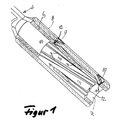
- a contact spring bush shown in FIGS. 1 to 5 for electrical connectors are in an originally smooth surface Strip 1 of a strip material made of an electrically conductive sheet material
- a large number of free cuts 2 are punched out, such that between the punched out Open cuts 2, in the embodiment shown strip-shaped, contacting means 3 remain, which have a rectangular cross-sectional shape and also connected to each other at both ends via an edge strip 4 or 5 stay.
- contacting means 3 is also simultaneously a crimp connection 6 cut out of the strip of strip material 1.
- the one with the the contact spring bushing 7 forming cut areas in one piece, crimp connections 6 forming cutting areas remain in total and constantly with one an area of the starting material forming a transport strip.
- the Contact spring bushing 7 is in turn in one of the two embodiments shown through a flat material section rolled into a cylinder body formed, stable sleeve body 8 received and fixed positively.
- the stable sleeve body is 8 with two cut out and aligned opposite to each other Center of the sleeve body 8 through, designed as tongues 9 and 10 Provide free cuts, the tongues 9 and 10 with their free ends 11 each rest on the inner end face 12 of the edge strips 4 and 5 and so a stable axial and radial support of the contact spring bushing 7 in the stable Form sleeve body 8.
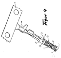
- the edge strip 4 as is particularly clear from the illustration in FIG. 4 evident, a rectangular plan and in the circumferential direction of the edge strip 4 aligned window recess 13.
- the stable sleeve body 8 Complementary to the window recess 13 there are two in the stable sleeve body 8 likewise aligned in the circumferential direction, arranged opposite one another and cut free tongues 14 and 15 with their free ends and bent inward with respect to the contact sleeve such that they in positive engagement with the narrow edges 16 and 17 of the window recess 13 stand.
- the two tongues 14 and 15 are in the shown Embodiment in one of the two longitudinal edges 18 or 19 of the sleeve body 8 sheet metal blank cut out expired cut out. Is further from the illustration in FIG.
Landscapes
- Manufacturing Of Electrical Connectors (AREA)
- Coupling Device And Connection With Printed Circuit (AREA)
- Connector Housings Or Holding Contact Members (AREA)
- Connecting Device With Holders (AREA)
Abstract
Description
Eine erste bekannte Bauart einer solchen Kontaktbuchse zeichnet sich dadurch aus, daß die Kontaktfederbuchse eine Anzahl von Kontaktstreifen aufweist, welche insgesamt schräg zur Längsachse der Kontaktfederbuchse ausgerichtet sind. Charakteristisch für Kontaktbuchsen dieser Ausgestaltung ist der Umstand, daß deren Kontaktfederbuchsen eine Anzahl von streifenförmigen Kontaktierungsmitteln aufweisen, die aus einer Anzahl durch Ausstanzen eines fortlaufenden Streifens eines Kontaktmaterials gebildeten und am oberen und unteren Ende der Kontaktfederbuchse über Randstreifen untereinander verbunden bleibenden Kontaktstreifen gebildet sind. Im Zusammenhang mit der Anwendung aus einem Kontaktmaterial freigeschnittener streifenförmiger Kontaktierungsmittel ist es ferner bekannt die mittels entsprechender Ausstanzungen aus einem fortlaufenden Materialstreifen hergestellten und zu einer Kontaktfederbuchse bzw. einer Kontaktierungsauskleidung eines stabilen Hülsenkörpers gerollten Zuschnitte entlang schräger Schnittlinien vom fortlaufenden Materialstreifen abzulängen und die beiden Schnittkanten des die Kontaktfederbuchse bildenden Zuschnittes dann entlang einer schräg zur Buchsenachse ausgerichteten Verbindungslinie miteinander zu verbinden, um eine schräg zur Buchsenachse ausgerichtete bzw. um die Buchsenachse tordiert ausgerichtete Anordnung der streifenförmigen Kontaktierungen zu erreichen.
- Figur 1
- eine teilweise aufgeschnittene schaubildliche Darstellung einer ersten Verwirklichungsform einer Kontaktbuchse;
- Figur 2
- eine schaubildliche Darstellung einer zweiten Verwirklichungsform einer Kontaktbuchse;
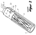
- Figur 3
- eine aufgeschnittene Darstellung der zweiten Verwirklichungsform nach Figur 2;
- Figur 4
- eine schaubildliche Einzeldarstellung einer Kontaktfederbuchse mit angeformtem Crimpteil;
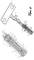
- Figur 5
- eine schaubildliche Darstellung der Lage einer Kontaktfederbuchse in einem stabilen Hülsenkörper.
Claims (8)
- Kontaktbuchse für elektrische Steckverbinder, welche aus einen stabilen aus einem Blechmaterial gebildeten Hülsenkörper und einer in diesem einliegenden, eine Vielzahl mit einem in die Buchse einzuführenden Kontaktstift in linienförmigen oder streifenförmigen Kontakt tretender Kontaktierungsmitteln, wie Kontaktdrähte oder Kontaktstreifen aufweisenden, Kontaktfederbuchse besteht, wobei die Kontaktdrähte oder Kontaktstreifen der Kontaktfederbuchse um die Buchsenachse verdreht ausgerichtet und beidendig mit einem Randstreifen aus Blech-material verbunden sind, und wobei ferner die Kontaktfederbuchse mechanisch und elektrisch mit dem Hülsenkörper verbunden ist,
dadurch gekennzeichnet,
daß der Hülsenkörper mit wenigstens einem quer zur Längsachse der Kontaktbuchse gerichteten und mindestens durch eine Ausprägung gebildeten Vorsprung versehen ist, welcher mit einem der beiden die Kontaktdrähte oder Kontaktstreifen der Kontaktfederbuchse untereinander verbindenden Randstreifen aus Blechmaterial im formschlüssigen Eingriff steht. - Kontaktbuchse nach Anspruch 1, dadurch gekennzeichnet, daß die Kontaktierungsmittel der Kontaktfederbuchse aus einer aus einem fortlaufenden Bandmaterial freigestanzten Kontaktstreifenfolge bestehen und untereinander beidendig über Randstreifen des fortlaufenden Bandmaterials untereinander verbunden sowie in gleichbleibenden gegenseitigen Abständen gehalten sind und daß der Hülsenkörper zwei in axialer Richtung zueinander beabstandete Ausprägungen aufweist deren jede mit jeweils einem der beiden die Kontaktstreifen beidendig untereinander verbindenden Randstreifen im formschlüssigen Eingriff steht.
- Kontaktbuchse nach Anspruch 1 und 2, dadurch gekennzeichnet, daß die radial zu dessen Längsachse gerichteten Vorsprünge des Hülsenkörpers durch zungenförmige nach innen durchgestellte Freischnitte gebildet sind und jeweils in eine Lücke zwischen benachbarten Kontaktstreifen der Kontaktfederbuchse eingreifend formschlüssig am inneren Rand der die Kontaktstreifen beidendig untereinander verbindenden Randstreifen anliegen.
- Kontaktbuchse nach Anspruch 1, dadurch gekennzeichnet, daß mindestens einer der beiden die Kontaktstreifen der Kontaktfederbuchse beidendig untereinander verbindenden Randstreifen mit einer Fensterausnehmung versehen ist und der Hülsenkörper wenigstens eine freigeschnittene und in einer nach innen durchgestellten Lage mit der Fensterausnehmung im formschlüssigen Eingriff stehende Zunge aufweist.
- Kontaktbuchse nach Anspruch 1 und 4, dadurch gekennzeichnet, daß die Fensterausnehmung in dem dem freien Ende der Kontaktbuchse gegenüberliegenden Randstreifen angeordnet und in Umfangsrichtung der Kontaktfederbuchse ausgerichtet ist.
- Kontaktbuchse nach einem der voraufgehenden Ansprüche 1 und 4 bzw. 5, dadurch gekennzeichnet, daß die in dem dem freien Ende der Kontaktbuchse gegenüberliegenden Randstreifen der Kontaktfederbuchse angeordnete Fensterausnehmung eine rechteckige Grundrißform aufweist und im Hülsenkörper zwei einander gegenüberliegende und nach innen abgewinkelte Zungen freigeschnitten sind, welche mit den Schmalseiten der Fensterausnehmung im formschlüssigen Eingriff stehen.
- Kontaktbuchse nach einem der voraufgehenden Ansprüche 1 bis 6, dadurch gekennzeichnet, daß die beiden im Hülsenkörper freigeschnittenen Zungen gegeneinander zeigend ausgerichtet und jede der beiden Zungen in einen der beiden Längsränder des den Hülsenkörper bildenden Blechmaterialzuschnittes auslaufend freigeschnitten ist.
- Kontaktbuchse nach einem der voraufgehenden Ansprüche 1 bis 7, dadurch gekennzeichnet, daß die Stoßränder des die Kontaktfederbuchse bildenden Materialzuschnittes und des den Hülsenkörper bildenden Materialzuschnittes um wenigstens 45° gegeneinander verdreht angeordnet sind.
Applications Claiming Priority (2)
| Application Number | Priority Date | Filing Date | Title |
|---|---|---|---|
| DE19933091A DE19933091A1 (de) | 1999-07-15 | 1999-07-15 | Kontaktbuchse für elektrische Steckverbinder |
| DE19933091 | 1999-07-15 |
Publications (2)
| Publication Number | Publication Date |
|---|---|
| EP1069652A1 true EP1069652A1 (de) | 2001-01-17 |
| EP1069652B1 EP1069652B1 (de) | 2003-09-17 |
Family
ID=7914832
Family Applications (1)
| Application Number | Title | Priority Date | Filing Date |
|---|---|---|---|
| EP00114141A Expired - Lifetime EP1069652B1 (de) | 1999-07-15 | 2000-07-11 | Kontaktbuchse für elektrische Steckverbinder |
Country Status (4)
| Country | Link |
|---|---|
| US (1) | US6425786B1 (de) |
| EP (1) | EP1069652B1 (de) |
| AT (1) | ATE250286T1 (de) |
| DE (2) | DE19933091A1 (de) |
Cited By (3)
| Publication number | Priority date | Publication date | Assignee | Title |
|---|---|---|---|---|
| WO2007084085A3 (en) * | 2006-01-19 | 2007-09-07 | Mkem Spol S R O | Contact tube with lamella |
| WO2017121564A1 (de) * | 2015-12-15 | 2017-07-20 | Amphenol-Tuchel Electronics Gmbh | Radialkontaktbuchse |
| CN108110469A (zh) * | 2018-01-26 | 2018-06-01 | 深圳市特拉利线簧端子技术有限公司 | 一种金属簧片、插孔组件及电连接器 |
Families Citing this family (16)
| Publication number | Priority date | Publication date | Assignee | Title |
|---|---|---|---|---|
| JP2004509440A (ja) * | 2000-09-15 | 2004-03-25 | アルコア フジクラ リミテッド | 車両部品用電気的端子ソケット組立体 |
| US6860768B2 (en) * | 2000-09-15 | 2005-03-01 | Alcoa Fujikura Limited | Combination sleeve and spring cage incorporated into a one-piece female terminal for interengaging a corresponding male terminal and method of configuring such a sleeve and spring cage from a blank shape |
| US6656002B2 (en) * | 2000-09-15 | 2003-12-02 | Alcoa Fujikura Limited | Electrical terminal socket assembly including T shaped sealed connectors |
| DE10235058A1 (de) * | 2002-07-31 | 2004-02-12 | Siemens Ag | Leitfähiges Kontaktstück für eine lösbare elektrische Steckverbindung |
| DE10235053A1 (de) * | 2002-07-31 | 2004-02-12 | Siemens Ag | Verfahren zur Herstellung eines Kontaktstückes |
| US6848922B2 (en) * | 2003-03-10 | 2005-02-01 | Hypertronics Corporation | Socket contact with integrally formed arc arresting portion |
| US6997750B2 (en) * | 2003-07-23 | 2006-02-14 | Fci Americas Technology, Inc. | Electrical connector contact |
| DE102005043692A1 (de) * | 2005-09-14 | 2007-03-15 | Robert Bosch Gmbh | Elektrischer Steckverbinder mit vorgespannten Kontaktlamellen |
| CH704749B1 (fr) * | 2007-09-05 | 2012-10-15 | Preci Dip Sa | Clip de contact. |
| DE202010003649U1 (de) * | 2010-03-16 | 2010-07-15 | Rosenberger Hochfrequenztechnik Gmbh & Co. Kg | Hochstromsteckverbinder |
| DE102011054316B4 (de) * | 2011-10-07 | 2021-04-01 | Te Connectivity Germany Gmbh | Zweiteiliges Crimpkontaktelement |
| US20150244096A1 (en) * | 2014-02-27 | 2015-08-27 | Amphenol Corporation | Electrical socket with improved misalignment tolerance |
| WO2018063928A1 (en) * | 2016-09-30 | 2018-04-05 | Molex, Llc | Socket connector |
| CN106684603A (zh) * | 2017-03-03 | 2017-05-17 | 王轶 | 一种具有转簧接触件的紧凑型插孔连接器 |
| CN108365371B (zh) * | 2017-11-07 | 2020-10-02 | 得意精密电子(苏州)有限公司 | 电连接器及电连接器的制造方法 |
| US10541489B2 (en) | 2018-03-29 | 2020-01-21 | Amphenol Corporation | Electrical socket with contoured contact beams |
Citations (3)
| Publication number | Priority date | Publication date | Assignee | Title |
|---|---|---|---|---|
| US5147230A (en) * | 1991-12-19 | 1992-09-15 | General Motors Corporation | Two piece electrical female terminal |
| US5474479A (en) * | 1994-09-28 | 1995-12-12 | The Whitaker Corporation | Louvered contact electrical connector |
| US5921822A (en) * | 1995-07-25 | 1999-07-13 | Framatome Connectors Interlock Inc. | Connector assembly |
Family Cites Families (10)
| Publication number | Priority date | Publication date | Assignee | Title |
|---|---|---|---|---|
| US4128293A (en) * | 1977-11-02 | 1978-12-05 | Akzona Incorporated | Conductive strip |
| DE2852267C2 (de) * | 1978-12-02 | 1982-02-18 | Wampfler Gmbh, 7858 Weil | Verbindungsvorrichtung für Schleifleitungen |
| DE3531845C2 (de) * | 1985-09-06 | 1994-05-26 | Daut & Rietz Trw | Kontaktteil, geformt als Buchsen- oder Steckerteil zum Einsetzen in Buchsen- oder Steckergehäusen |
| DE3625384A1 (de) * | 1986-07-26 | 1988-02-04 | Reinshagen Kabelwerk Gmbh | Elektrische steckverbindung |
| US4973272A (en) * | 1987-01-30 | 1990-11-27 | Wyle Laboratories | Electrical connector with contactors |
| DE4203379A1 (de) * | 1992-02-06 | 1993-08-12 | Daut & Rietz Trw | Federkontakt fuer elektrische flachstecksysteme |
| US5810627A (en) * | 1996-01-11 | 1998-09-22 | Molex Incorporated | Female electrical terminal |
| FR2758213B1 (fr) * | 1997-01-07 | 1999-01-29 | Cinch Connecteurs Sa | Organe de contact electrique femelle |
| US6062919A (en) * | 1997-08-29 | 2000-05-16 | Thomas & Betts International, Inc. | Electrical connector assembly having high current-carrying capability and low insertion force |
| DE19802821B4 (de) * | 1998-01-26 | 2008-02-07 | The Whitaker Corp., Wilmington | Elektrische Anschlußklemme |
-
1999
- 1999-07-15 DE DE19933091A patent/DE19933091A1/de not_active Withdrawn
-
2000
- 2000-07-11 AT AT00114141T patent/ATE250286T1/de active
- 2000-07-11 DE DE50003701T patent/DE50003701D1/de not_active Expired - Lifetime
- 2000-07-11 EP EP00114141A patent/EP1069652B1/de not_active Expired - Lifetime
- 2000-07-12 US US09/614,315 patent/US6425786B1/en not_active Expired - Lifetime
Patent Citations (3)
| Publication number | Priority date | Publication date | Assignee | Title |
|---|---|---|---|---|
| US5147230A (en) * | 1991-12-19 | 1992-09-15 | General Motors Corporation | Two piece electrical female terminal |
| US5474479A (en) * | 1994-09-28 | 1995-12-12 | The Whitaker Corporation | Louvered contact electrical connector |
| US5921822A (en) * | 1995-07-25 | 1999-07-13 | Framatome Connectors Interlock Inc. | Connector assembly |
Cited By (5)
| Publication number | Priority date | Publication date | Assignee | Title |
|---|---|---|---|---|
| WO2007084085A3 (en) * | 2006-01-19 | 2007-09-07 | Mkem Spol S R O | Contact tube with lamella |
| WO2017121564A1 (de) * | 2015-12-15 | 2017-07-20 | Amphenol-Tuchel Electronics Gmbh | Radialkontaktbuchse |
| US10535943B2 (en) | 2015-12-15 | 2020-01-14 | Amphenol-Tuchel Electronics Gmbh | Radial contact socket |
| CN108110469A (zh) * | 2018-01-26 | 2018-06-01 | 深圳市特拉利线簧端子技术有限公司 | 一种金属簧片、插孔组件及电连接器 |
| CN108110469B (zh) * | 2018-01-26 | 2024-04-05 | 深圳市特拉利线簧端子技术有限公司 | 一种金属簧片、插孔组件及电连接器 |
Also Published As
| Publication number | Publication date |
|---|---|
| DE19933091A1 (de) | 2001-02-01 |
| DE50003701D1 (de) | 2003-10-23 |
| ATE250286T1 (de) | 2003-10-15 |
| EP1069652B1 (de) | 2003-09-17 |
| US6425786B1 (en) | 2002-07-30 |
Similar Documents
| Publication | Publication Date | Title |
|---|---|---|
| EP1069652A1 (de) | Kontaktbuchse für elektrische Steckverbinder | |
| DE3817803C2 (de) | ||
| EP1103088B1 (de) | Buchsenkontakt | |
| EP0520950A1 (de) | Kontaktorgan und Verfahren zur Herstellung des Kontaktorgans | |
| EP3196981B1 (de) | Querverbinder für reihenklemmen | |
| DE10310899B3 (de) | Elektrische Kontaktiervorrichtung | |
| EP0716474A1 (de) | Kontaktelement zum Verbinden zweier Kontaktstücke | |
| EP0536523B1 (de) | Anschlussklemme | |
| DE3116731C2 (de) | Kontaktelement | |
| EP0198408B1 (de) | Werkzeug zur Herstellung eines elektrischen Kontaktstiftes für gedruckte Schaltungsplatten | |
| DE102005017988B3 (de) | Elektrische Kontakthülse | |
| DE202008008656U1 (de) | Schutzleiteranschlußvorrichtung aus Metall | |
| DE102005063286A1 (de) | Kontaktbuchse für einen Steckerstift | |
| DE69503902T2 (de) | Kontakt für schneidklemmverbinder | |
| DE102019204704A1 (de) | Aufwickelbarer Stanzstreifen mit erhöhter Flexibilität | |
| EP1763111B1 (de) | Buchsenkontakt mit mindestens zwei in Steckrichtung angeordneten Kontaktpunkten | |
| DE29912351U1 (de) | Kontaktbuchse für elektrische Steckverbinder | |
| EP1114493A1 (de) | Verfahren zur herstellung von kontaktbuchsen für elektrische steckverbinder | |
| DE29805916U1 (de) | Kontaktbuchse für elektrische Steckverbinder | |
| EP0650222B1 (de) | Elektrische Flachsteckkontaktbuchse | |
| BE1032048B1 (de) | Lamellenkörper für ein Steckverbinderteil | |
| BE1032011B1 (de) | Elektrisches Kontaktelement | |
| DE9304392U1 (de) | Kontaktelement mit Schneidklemm- und Crimpanschluß | |
| EP1213790A2 (de) | Elektrische Anschlussklemme | |
| DE10237830A1 (de) | Elektrischer Steckkontaktkörper |
Legal Events
| Date | Code | Title | Description |
|---|---|---|---|
| PUAI | Public reference made under article 153(3) epc to a published international application that has entered the european phase |
Free format text: ORIGINAL CODE: 0009012 |
|
| AK | Designated contracting states |
Kind code of ref document: A1 Designated state(s): AT BE CH CY DE DK ES FI FR GB GR IE IT LI LU MC NL PT SE |
|
| AX | Request for extension of the european patent |
Free format text: AL;LT;LV;MK;RO;SI |
|
| 17P | Request for examination filed |
Effective date: 20010306 |
|
| AKX | Designation fees paid |
Free format text: AT BE CH CY DE DK ES FI FR GB GR IE IT LI LU MC NL PT SE |
|
| GRAH | Despatch of communication of intention to grant a patent |
Free format text: ORIGINAL CODE: EPIDOS IGRA |
|
| 17Q | First examination report despatched |
Effective date: 20021202 |
|
| GRAH | Despatch of communication of intention to grant a patent |
Free format text: ORIGINAL CODE: EPIDOS IGRA |
|
| GRAA | (expected) grant |
Free format text: ORIGINAL CODE: 0009210 |
|
| AK | Designated contracting states |
Kind code of ref document: B1 Designated state(s): AT BE CH CY DE DK ES FI FR GB GR IE IT LI LU MC NL PT SE |
|
| PG25 | Lapsed in a contracting state [announced via postgrant information from national office to epo] |
Ref country code: IE Free format text: LAPSE BECAUSE OF FAILURE TO SUBMIT A TRANSLATION OF THE DESCRIPTION OR TO PAY THE FEE WITHIN THE PRESCRIBED TIME-LIMIT Effective date: 20030917 Ref country code: CY Free format text: LAPSE BECAUSE OF FAILURE TO SUBMIT A TRANSLATION OF THE DESCRIPTION OR TO PAY THE FEE WITHIN THE PRESCRIBED TIME-LIMIT Effective date: 20030917 Ref country code: FI Free format text: LAPSE BECAUSE OF FAILURE TO SUBMIT A TRANSLATION OF THE DESCRIPTION OR TO PAY THE FEE WITHIN THE PRESCRIBED TIME-LIMIT Effective date: 20030917 Ref country code: NL Free format text: LAPSE BECAUSE OF FAILURE TO SUBMIT A TRANSLATION OF THE DESCRIPTION OR TO PAY THE FEE WITHIN THE PRESCRIBED TIME-LIMIT Effective date: 20030917 |
|
| REG | Reference to a national code |
Ref country code: GB Ref legal event code: FG4D Free format text: NOT ENGLISH |
|
| REG | Reference to a national code |
Ref country code: CH Ref legal event code: EP |
|
| REF | Corresponds to: |
Ref document number: 50003701 Country of ref document: DE Date of ref document: 20031023 Kind code of ref document: P |
|
| REG | Reference to a national code |
Ref country code: IE Ref legal event code: FG4D Free format text: GERMAN |
|
| PG25 | Lapsed in a contracting state [announced via postgrant information from national office to epo] |
Ref country code: GR Free format text: LAPSE BECAUSE OF FAILURE TO SUBMIT A TRANSLATION OF THE DESCRIPTION OR TO PAY THE FEE WITHIN THE PRESCRIBED TIME-LIMIT Effective date: 20031217 Ref country code: SE Free format text: LAPSE BECAUSE OF FAILURE TO SUBMIT A TRANSLATION OF THE DESCRIPTION OR TO PAY THE FEE WITHIN THE PRESCRIBED TIME-LIMIT Effective date: 20031217 Ref country code: DK Free format text: LAPSE BECAUSE OF FAILURE TO SUBMIT A TRANSLATION OF THE DESCRIPTION OR TO PAY THE FEE WITHIN THE PRESCRIBED TIME-LIMIT Effective date: 20031217 |
|
| PG25 | Lapsed in a contracting state [announced via postgrant information from national office to epo] |
Ref country code: PT Free format text: LAPSE BECAUSE OF FAILURE TO SUBMIT A TRANSLATION OF THE DESCRIPTION OR TO PAY THE FEE WITHIN THE PRESCRIBED TIME-LIMIT Effective date: 20031226 |
|
| PG25 | Lapsed in a contracting state [announced via postgrant information from national office to epo] |
Ref country code: ES Free format text: LAPSE BECAUSE OF FAILURE TO SUBMIT A TRANSLATION OF THE DESCRIPTION OR TO PAY THE FEE WITHIN THE PRESCRIBED TIME-LIMIT Effective date: 20031228 |
|
| REG | Reference to a national code |
Ref country code: CH Ref legal event code: NV Representative=s name: KIRKER & CIE SA Ref country code: CH Ref legal event code: PFA Owner name: HYPERTAC GMBH Free format text: INTERCONNECTRON GMBH#AUWIESENSTRASSE 5#94469 DEGGENDORF (DE) -TRANSFER TO- HYPERTAC GMBH#AUWIESENSTRASSE 5#94469 DEGGENDORF (DE) |
|
| GBT | Gb: translation of ep patent filed (gb section 77(6)(a)/1977) |
Effective date: 20040104 |
|
| RAP2 | Party data changed (patent owner data changed or rights of a patent transferred) |
Owner name: HYPERTAC GMBH |
|
| NLV1 | Nl: lapsed or annulled due to failure to fulfill the requirements of art. 29p and 29m of the patents act | ||
| REG | Reference to a national code |
Ref country code: IE Ref legal event code: FD4D |
|
| ET | Fr: translation filed | ||
| PG25 | Lapsed in a contracting state [announced via postgrant information from national office to epo] |
Ref country code: LU Free format text: LAPSE BECAUSE OF NON-PAYMENT OF DUE FEES Effective date: 20040711 |
|
| PLBE | No opposition filed within time limit |
Free format text: ORIGINAL CODE: 0009261 |
|
| STAA | Information on the status of an ep patent application or granted ep patent |
Free format text: STATUS: NO OPPOSITION FILED WITHIN TIME LIMIT |
|
| PG25 | Lapsed in a contracting state [announced via postgrant information from national office to epo] |
Ref country code: MC Free format text: LAPSE BECAUSE OF NON-PAYMENT OF DUE FEES Effective date: 20040731 Ref country code: BE Free format text: LAPSE BECAUSE OF NON-PAYMENT OF DUE FEES Effective date: 20040731 |
|
| 26N | No opposition filed |
Effective date: 20040618 |
|
| BERE | Be: lapsed |
Owner name: *INTERCONNECTRON G.M.B.H. Effective date: 20040731 |
|
| BERE | Be: lapsed |
Owner name: *INTERCONNECTRON G.M.B.H. Effective date: 20040731 |
|
| REG | Reference to a national code |
Ref country code: FR Ref legal event code: CD |
|
| REG | Reference to a national code |
Ref country code: FR Ref legal event code: PLFP Year of fee payment: 17 |
|
| REG | Reference to a national code |
Ref country code: FR Ref legal event code: PLFP Year of fee payment: 18 |
|
| PGFP | Annual fee paid to national office [announced via postgrant information from national office to epo] |
Ref country code: CH Payment date: 20170712 Year of fee payment: 18 |
|
| PGFP | Annual fee paid to national office [announced via postgrant information from national office to epo] |
Ref country code: AT Payment date: 20170626 Year of fee payment: 18 |
|
| REG | Reference to a national code |
Ref country code: FR Ref legal event code: PLFP Year of fee payment: 19 |
|
| REG | Reference to a national code |
Ref country code: CH Ref legal event code: PL |
|
| REG | Reference to a national code |
Ref country code: AT Ref legal event code: MM01 Ref document number: 250286 Country of ref document: AT Kind code of ref document: T Effective date: 20180711 |
|
| PG25 | Lapsed in a contracting state [announced via postgrant information from national office to epo] |
Ref country code: CH Free format text: LAPSE BECAUSE OF NON-PAYMENT OF DUE FEES Effective date: 20180731 Ref country code: AT Free format text: LAPSE BECAUSE OF NON-PAYMENT OF DUE FEES Effective date: 20180711 Ref country code: LI Free format text: LAPSE BECAUSE OF NON-PAYMENT OF DUE FEES Effective date: 20180731 |
|
| PGFP | Annual fee paid to national office [announced via postgrant information from national office to epo] |
Ref country code: FR Payment date: 20190619 Year of fee payment: 20 |
|
| PGFP | Annual fee paid to national office [announced via postgrant information from national office to epo] |
Ref country code: DE Payment date: 20190625 Year of fee payment: 20 Ref country code: IT Payment date: 20190719 Year of fee payment: 20 |
|
| PGFP | Annual fee paid to national office [announced via postgrant information from national office to epo] |
Ref country code: GB Payment date: 20190710 Year of fee payment: 20 |
|
| REG | Reference to a national code |
Ref country code: DE Ref legal event code: R071 Ref document number: 50003701 Country of ref document: DE |
|
| REG | Reference to a national code |
Ref country code: GB Ref legal event code: PE20 Expiry date: 20200710 |
|
| PG25 | Lapsed in a contracting state [announced via postgrant information from national office to epo] |
Ref country code: GB Free format text: LAPSE BECAUSE OF EXPIRATION OF PROTECTION Effective date: 20200710 |