EP1069404B1 - Procede et appareil de navigation - Google Patents
Procede et appareil de navigation Download PDFInfo
- Publication number
- EP1069404B1 EP1069404B1 EP99901902A EP99901902A EP1069404B1 EP 1069404 B1 EP1069404 B1 EP 1069404B1 EP 99901902 A EP99901902 A EP 99901902A EP 99901902 A EP99901902 A EP 99901902A EP 1069404 B1 EP1069404 B1 EP 1069404B1
- Authority
- EP
- European Patent Office
- Prior art keywords
- time
- route
- obstacle
- information
- destination
- Prior art date
- Legal status (The legal status is an assumption and is not a legal conclusion. Google has not performed a legal analysis and makes no representation as to the accuracy of the status listed.)
- Expired - Lifetime
Links
Images


Classifications
-
- G—PHYSICS
- G08—SIGNALLING
- G08G—TRAFFIC CONTROL SYSTEMS
- G08G1/00—Traffic control systems for road vehicles
- G08G1/09—Arrangements for giving variable traffic instructions
- G08G1/0962—Arrangements for giving variable traffic instructions having an indicator mounted inside the vehicle, e.g. giving voice messages
- G08G1/0968—Systems involving transmission of navigation instructions to the vehicle
- G08G1/096805—Systems involving transmission of navigation instructions to the vehicle where the transmitted instructions are used to compute a route
- G08G1/096827—Systems involving transmission of navigation instructions to the vehicle where the transmitted instructions are used to compute a route where the route is computed onboard
-
- G—PHYSICS
- G01—MEASURING; TESTING
- G01C—MEASURING DISTANCES, LEVELS OR BEARINGS; SURVEYING; NAVIGATION; GYROSCOPIC INSTRUMENTS; PHOTOGRAMMETRY OR VIDEOGRAMMETRY
- G01C21/00—Navigation; Navigational instruments not provided for in groups G01C1/00 - G01C19/00
- G01C21/26—Navigation; Navigational instruments not provided for in groups G01C1/00 - G01C19/00 specially adapted for navigation in a road network
- G01C21/34—Route searching; Route guidance
- G01C21/3453—Special cost functions, i.e. other than distance or default speed limit of road segments
- G01C21/3492—Special cost functions, i.e. other than distance or default speed limit of road segments employing speed data or traffic data, e.g. real-time or historical
-
- G—PHYSICS
- G08—SIGNALLING
- G08G—TRAFFIC CONTROL SYSTEMS
- G08G1/00—Traffic control systems for road vehicles
- G08G1/09—Arrangements for giving variable traffic instructions
- G08G1/0962—Arrangements for giving variable traffic instructions having an indicator mounted inside the vehicle, e.g. giving voice messages
- G08G1/0968—Systems involving transmission of navigation instructions to the vehicle
- G08G1/096855—Systems involving transmission of navigation instructions to the vehicle where the output is provided in a suitable form to the driver
- G08G1/096872—Systems involving transmission of navigation instructions to the vehicle where the output is provided in a suitable form to the driver where instructions are given per voice
Definitions
- the present invention relates to a navigation device and method therefor which displays a recommended route which can be accomplished with reference to the shortest timeframe, when searching a route from a present position to a destination.
- Navigation devices for use in a moving body, for example an automobile, have recently enjoyed increasing popularity. Such devices calculate a recommended route from a present position of the vehicle to a destination on the basis of a destination set by a user. The recommended route is then displayed. Some devices provide for indicating the direction of turning with voice commands so that the route may be correctly selected at the next intersection.
- Devices which have the function of searching for recommended routes entail the problem of searching for the route on the basis of some kind of standard. Normally this is defined as a route which is "short" with respect to distance or time. However the selection of the shortest route with respect to time entails the use of expressways and the resultant problem of increases in tolls. It is difficult to search for a route in consideration of all parameters. Normally a method of selecting a route, which satisfies a user, is adopted in which the user selects each condition in order of priority.
- the present invention proposes an improvement related to a device which searches a route on the basis that travelling time is prioritized.
- the present invention prioritizes time by analyzing the speed limits set on each road divided into a number of sections.
- the recommended route is assumed to be the combination of routes having the smallest total for the time required for the divided sections.
- the route as calculated above may not be the shortest route as regards time and a detour may be shorter.
- JP-A-9-5100 An invention which addresses the above problem is disclosed for example in JP-A-9-5100 .
- this invention the presence of railway crossings and the timetables of main stations are included in road data.
- routes which include railway crossings with long waiting times are excluded by a weighting process which corresponds to the number of trains passing in unit time.
- JP-A-7-229746 discloses a device in which the timetables of all modes of transportation are stored. This enables an estimation of the waiting time at railway crossings which intersect with the road by displaying superimposed timetables on the road map in conjunction with the progress of the moving body.
- EP 0 703 436 A2 discloses a navigation system for vehicles which searches routes depending on different parameters, inter alia depending on the traffic signal waiting time or on the occurence of a traffic jam.
- US 5 818 356 describes a device for guiding vehicles as a function of the traffic situation using a control center computer for determining the optimum route as a function of traffic situation data and sending the navigation data to a vehicle-end navigation device.
- the present invention is proposed to solve the above problems and has the object of providing a navigation device and method therefor which can increase the searching accuracy for a recommended route along which a vehicle can travel in the shortest time.
- the navigation device of the present invention is provided with a route searching means which refers to delay time information which is obtained from an information acquisition means and which searches for a recommended route along which movement is possible in the shortest time from a present position of a moving body detected by a detection means to a destination which is set by a setting means.
- the route searching device searches a recommended route by adding waiting time, which is the time at which the vehicle will pass, to the time taken for the vehicle to travel from a present position to a destination.
- the navigation device of the present invention is provided with an information acquisition means which reads obstacle time information from a recording medium.
- the navigation device of the present invention is provided with an information acquisition means which receives radio signals relating to obstacle time information.
- the navigation method of the present invention consists of searching for a the shortest recommended route with respect to time from a present position to a destination by referring to obstacle time information about obstacles on the route.
- the navigation method of the present invention consists of searching a recommended route by adding waiting time, which is the time by which a vehicle can pass an obstacle, to the time taken for the vehicle to travel from a present position to a destination, when the vehicle is in a time range in which the forecast time of the vehicle to reach an obstacle will result in a delay.
- the navigation method of the present invention consists of reading obstacle time information from a recording medium.
- the navigation method of the present invention consists of receiving a radio signal related to obstacle time information.
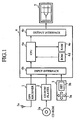
- FIG. 1 is a diagram showing the navigation device according to a first embodiment of the present invention.
- reference numeral 1 denotes a known GPS receiver (position detection means) which detects a present position of the moving body (for example an automobile).
- the GPS receiver receives positional information from a GPS satellite via an antenna 1a.
- 2 is a CD-ROM playing device (information acquisition means) which acquires map information which is geographical information regarding roads, railways, railway crossings and the like and which acquires obstacle time information regarding obstacles (for example railway crossings) on the route which are in a delaying time range. Obstacle time information and map information are recorded in the CD-ROM 2a which acts as a recording medium.
- 3 is an operation device (setting means) which sets the destination of the vehicle and which consists of a cursor displacement device 3a and a set button 3b.
- 4 is a microcomputer (route searching means) which searches the shortest recommended route with respect to time taking into account obstacles such as railway crossings from a present position to a destination based on information from a GPS receiver 1, CD-ROM player 2 and an operation device 3.
- the microcomputer 3 comprises a CPU 4a, an input interface 4b, an output interface 4c, a ROM 4d and a RAM 4e.
- 5 is an LCD panel (display means) which displays information relating a recommended route searched by the microcomputer 4.
- Figure 2 shows an example of a road map displayed on the LCD panel 5.
- D1-D6 are roads
- N1-N6 are initial or terminal points of roads
- R is a railway
- B is a bridge for the road D2
- F3 is a railway crossing
- C is a mark showing the present position of the vehicle
- G is a mark showing a destination
- M is the cursor of the operation device 3.
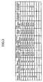
- a memory map in the form as shown in Figure 3 is stored in the CD-ROM with map information, and more particularly road information, for the purposes of generating the above map.
- a road D1 comprises the line from the initial point N1 to the terminal point N2.
- the coordinates of the initial and terminal points N1 and N2 are the respective coordinates (X1, Y1), (X2, Y2).
- the actual distance is displayed as 10km, the speed limit as 60km/h, and railway crossing positions as "0" that is to say there are no railway crossings.
- the road depicted in Figure 2 is created on the basis of the above road information.
- the road D5 has data "N5" stored showing the position of a railway crossing, the crossing at the terminal point N5 is displayed as "YES".
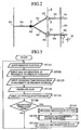
- FIGS 5 and 6 are flowcharts which show the operation of the microcomputer 4.
- step ST101 in Figure 5 the GPS receiver 1 inputs coordinates (X, Y) representing the present detected position of the vehicle.
- step ST102 map information regarding the surroundings of the present position are input from the CD-ROM player 2.
- step ST103 time information relating to railway crossings in the vicinity of the present position is input from the CD-ROM player 2.
- step ST104 map information from the CD-ROM player 2 is displayed on the LCD panel 5. In this way, the roads D1-D6, the railway crossings F3, the bridge B, the railway R and the like as shown in Figure 2 , are created.
- a mark C which displays a present position of the vehicle is displayed on the LCD panel 5 (refer to Figure 2 ).
- step ST106 it is detected whether or not the operation device is operating. In the event that it is not operating, the routine is repeated by returning to the step ST101. If it is operating, the destination is set (step ST107).
- step ST107 the destination is set and the destination mark G is created by the user moving the cursor M displayed on the LCD panel 5 (refer to Figure 2 ) with the cursor operation device 3a and pushing the set button 3b at a desired position.
- a candidate route is searched from a current position of the vehicle C to a destination D.
- the example shown in Figure 2 shows two types of route from the present position C to a destination D.
- a first route is D5, D6 and a second route is D2, D3, D4.
- the total distance of each route is calculated from actual distance data acquired from the map information shown in Figure 3 with the result that the first route is 20km and the second route is 30 km long.
- the first route can be seen to be the shortest.
- the required time for the first route will be calculated as 20 minutes and that of the second route as 30 minutes on the basis of the speed limits for the roads shown in Figure 3 .
- the first route is the one that enables arrival in the shortest time.
- the railway crossing F3 since there is a railway crossing F3 along the first route, if the railway crossing F3 is open when the vehicle arrives at the railway crossing F3, it is possible to arrive at the destination in a shorter maximum time than the second route. If the vehicle arrives at the railway crossing just when it is closing, the necessary time to travel from a present position to the destination G will be 40 minutes as waiting time will amount to 20 minutes. Therefore selecting the first route which contains the railway crossing F3 may produce longer or shorter travelling times than the second route depending on the time at which the vehicle reaches the crossing.
- the first embodiment is adapted to allow normal arrival in a minimum time at a destination on the basis of the processing shown in Figure 6 .
- a candidate route is searched, and as a result, a number of routes N from a first route to a destination is extracted.
- an initial value 1 is set as a parameter n to make repeated calculations.
- a step ST203 it is determined whether a railway crossing is contained in the nth route. If one is not contained, in a step ST204, necessary travelling time is calculated from the map information in Figure 3 . The necessary travelling time for the nth route is taken to be T(n).
- a step ST205 the necessary travelling time Ta from the present position of the vehicle to the railway crossing F3 is calculated.
- the estimated time of arrival at the crossing T+Ta is calculated by adding the current travelling time T to this time Ta.
- a railway crossing waiting time Tb is calculated based on estimated time of arrival at the crossing T+Ta and the crossing time information in Figure 4 .
- the necessary travelling time Tc from a crossing F3 to a destination G is calculated.
- the sum of the respective times Ta, Tb, Tc is calculated and the required time from a present position of a vehicle at that time to a destination G is calculated.
- a step ST210 it is determined whether or not the above calculation has been executed N times to the Nth route. If it has not, in a step ST211, the parameter n is renewed. If it has, in a step ST212, the minimum required travelling time T(n) min is calculated on the entire route from a first route to an Nth route. In a step ST213, an nth route which, corresponds to the minimum required time T(n) min is set as a recommended route. The routine returns to the step ST109 in the main routine in Figure 5 and displays a route which corresponds to T(n) min.
- the display method entails for example, widening the line representing the roads D5, D6 if they are assumed to be a recommended route so that they are wider than other roads. Otherwise such roads may be depicted in a preset highlighting color in order to distinguish them from other roads or may be distinguished by other methods.
- the estimated time of arrival T+Ta at the crossing calculated in the step ST 206 is 7:05.
- the crossing time information in Figure 4 it is calculated that the vehicle will encounter the closing period of the crossing from 7:00 to 7:20 and so the railway crossing waiting time Tb will be 15 minutes.
- the required time Tc from the crossing F3 to the destination G is calculated to be 10 minutes from the map information in Figure 3 , the total required time T(1) is calculated to be 35 minutes in the step ST209.
- the required time T(2) on the second route calculated in the step ST204 is calculated to be 30 minutes with reference to the map information in Figure 3 .
- the second route D2, D3, D4 which passes the bridge B has a shorter minimum travelling time than the first route D5, D6 which passes the crossing F3, in the step ST212, the second route D2, D3, D4 is set as the recommended route.
- the estimated time of arrival T+Ta at the crossing calculated in the step ST206 is 7:15.
- the vehicle will encounter the same crossing closure period from 7:00 to 7:20.
- the crossing F3 waiting time will be 5 minutes.
- the total required time T(1) calculated in the step ST209 is 25 minutes.
- the required time T(2) on the second route is the 30 minutes as above, when the vehicle leaves from the point N2 at 7:05, since the first route which passes the crossing F3 has a shorter minimum travelling time than the second route which passes the bridge B, the first route D5, D6 is set in the step ST 213 as the recommended route.
- a recommended route which normally enables arrival at a destination in a minimum travelling time is indicated to a user at an arbitrary time, after consideration of the arrival time of a vehicle at a crossing and the times of closure of the crossings.
- the first embodiment used the example of a railway crossing as an obstacle.
- the invention is not limited in this respect and obviously may be adapted for use with a drawbridge which crosses a river.
- the moving body was taken to be an automobile.
- the invention is not limited in this respect and obviously may be adapted to a ship or pedestrian.
- FIG 7 is a schematic diagram of a navigation device according to a second embodiment of the present invention.
- those elements which are the same or similar to those shown in Figure 1 are represented by the same reference numerals and their explanation will be omitted.
- 6 is a radio telephone (information acquisition means) which receives most recent obstacle time information with respect to crossings via the Internet from a base station (not shown) which is provided outside the mobile body.
- 6a is an antenna of the radio telephone 6.
- 7 is a speaker (indication means) which announces the recommended route.
- obstacle time information was read and played from a CD-ROM 2b.
- obstacle time information regarding crossings need not be recorded and only map information may be recorded on such a CD-ROM 2b.
- Most recent information regarding crossings may be received by a radiotelephone 6 via the Internet from a base station provided outside the mobile body. (In step ST103 in Figure 5 , instead of the input from the CD-ROM player 2, most recent information about crossings may be input via the Internet.)
- the method of displaying the recommended route was by display on a LCD panel 5.
- the route may be indicated before arrival at critical points by voice commands such as "Turn right at the next intersection" by the provision of a speaker. In this way, safety is improved as the driver need not monitor the LCD panel 5 in order to select the route.
- the acquisition of crossing time information via the internet allows the calculation of a recommended route which has an accurate minimum time when timetables are interrupted by accidents or the like or when train timetables are revised.
- the second embodiment is the same as the first embodiment.
- the navigation device and navigation method of the present invention is adapted for the acquisition of varying obstacle time information and displays the time related to an obstacle which is located along a road and the time required to pass the obstacle.
- a recommended route is calculated from a present position of a moving body to a destination at a minimum time depending on the time to negotiate the obstacle.
- the display of this result is adapted for use on a navigation device for a moving body which reaches a destination in a minimum time.
Landscapes
- Engineering & Computer Science (AREA)
- Radar, Positioning & Navigation (AREA)
- Remote Sensing (AREA)
- Physics & Mathematics (AREA)
- General Physics & Mathematics (AREA)
- Automation & Control Theory (AREA)
- Navigation (AREA)
- Feeding And Guiding Record Carriers (AREA)
- Traffic Control Systems (AREA)
Abstract
Claims (6)
- Dispositif de navigation, comprenant :des moyens de détection de position (1), détectant une position actuelle d'un corps en déplacement;des moyens de réglage (3) réglant une destination;des moyens d'acquisition d'informations (2, 6), acquérant des informations cartographiques;des moyens de recherche d'itinéraire (4), recherchant un itinéraire en fonction du temps; etdes moyens d'indication (5) indiquant un itinéraire recommandé, ayant été recherché par lesdits moyens de recherche d'itinéraire (4);caractérisé en ce que lesdits moyens d'acquisition d'informations (2, 6) sont adaptés pour acquérir des informations de temps d'obstacle, relatives à un obstacle fermant l'itinéraire, ledit obstacle nécessitant du temps pour son franchissement; et lesdits moyens de recherche d'itinéraire (4) sont adaptés pour rechercher un itinéraire recommandé, depuis une position actuelle jusqu'à une destination, en considérant un temps d'attente, ledit temps d'attente étant la durée s'écoulant entre un instant d'arrivée escompté à l'obstacle et un instant auquel l'obstacle peut être franchi;
ledit itinéraire avec l'obstacle étant déterminé comme itinéraire recommandé, lorsque le temps de déplacement nécessaire, de la position actuelle à la destination, avec le temps d'attente, est inférieur à celui des autres itinéraires sans obstacles. - Dispositif de navigation selon la revendication 1, dans lequel lesdits moyens d'acquisition d'informations (2, 6) lisent des informations relatives à un temps d'obstacle, à partir d'un support d'enregistrement (2a).
- Dispositif de navigation selon la revendication 1, dans lequel ledit dispositif d'acquisition d'informations (6) reçoit un signal radio relatif à des informations de temps d'obstacle.
- Procédé de navigation, comprenant les étapes consistant à :déterminer une destination et rechercher une position actuelle d'un corps en déplacement;acquérir des informations cartographiques;rechercher un itinéraire recommandé; etindiquer ledit itinéraire recommandé, caractérisé en ce que lesdites informations de temps d'obstacle, relatives à un obstacle fermant un itinéraire, sont acquises, et un itinéraire recommandé est recherché en considérant un temps d'attente, ledit temps d'attente étant la durée s'écoulant entre un instant d'arrivée escompté à l'obstacle et un instant auquel l'obstacle peut être franchi,et ledit itinéraire avec obstacle est fixé comme itinéraire recommandé, lorsque le temps de déplacement nécessaire, de la position actuelle à la destination, avec le temps d'attente, est inférieur à celui d'autres itinéraires sans obstacles.
- Procédé de navigation selon la revendication 4, comprenant en outre l'étape de lecture d'informations relatives à un temps d'obstacle, à partir d'un support d'enregistrement.
- Procédé de navigation selon la revendication 4, comprenant en outre l'étape de réception d'un signal radio relatif à des informations de temps d'obstacle.
Applications Claiming Priority (1)
| Application Number | Priority Date | Filing Date | Title |
|---|---|---|---|
| PCT/JP1999/000365 WO2000045129A1 (fr) | 1999-01-28 | 1999-01-28 | Procede et appareil de navigation |
Publications (3)
| Publication Number | Publication Date |
|---|---|
| EP1069404A1 EP1069404A1 (fr) | 2001-01-17 |
| EP1069404A4 EP1069404A4 (fr) | 2006-02-08 |
| EP1069404B1 true EP1069404B1 (fr) | 2008-04-16 |
Family
ID=14234810
Family Applications (1)
| Application Number | Title | Priority Date | Filing Date |
|---|---|---|---|
| EP99901902A Expired - Lifetime EP1069404B1 (fr) | 1999-01-28 | 1999-01-28 | Procede et appareil de navigation |
Country Status (5)
| Country | Link |
|---|---|
| US (1) | US6304821B1 (fr) |
| EP (1) | EP1069404B1 (fr) |
| JP (1) | JP4270756B2 (fr) |
| DE (1) | DE69938545T2 (fr) |
| WO (1) | WO2000045129A1 (fr) |
Families Citing this family (6)
| Publication number | Priority date | Publication date | Assignee | Title |
|---|---|---|---|---|
| DE10006314A1 (de) * | 2000-02-12 | 2001-08-16 | Lesswire Ag | Mobile Informationsvorrichtung für eine Mobil-Kommunikationsumgebung |
| US20030009280A1 (en) * | 2001-01-05 | 2003-01-09 | Alcatel | Navigation method and navigation system |
| US20080243386A1 (en) * | 2007-03-27 | 2008-10-02 | Cisco Technology, Inc. | Method and System for Communicating Arrival Notifications |
| US20090076725A1 (en) | 2007-09-14 | 2009-03-19 | Kulvir Singh Bhogal | Conveyance mode aware navigation device |
| EP2583062B1 (fr) * | 2010-06-15 | 2017-08-09 | TomTom Global Content B.V. | Détection de position, tableau horaire et estimation des temps de trajet pour la traversée d'obstacles sur une carte numérique |
| GB2497981B (en) * | 2011-12-23 | 2013-11-13 | Charles Linfield Davies | Generating travel time data |
Family Cites Families (19)
| Publication number | Priority date | Publication date | Assignee | Title |
|---|---|---|---|---|
| JPS60125879A (ja) | 1983-12-09 | 1985-07-05 | マツダ株式会社 | 自動車のコ−ス誘導装置 |
| DE4008460A1 (de) * | 1990-03-16 | 1991-09-19 | Bosch Gmbh Robert | Navigationssystem |
| US5845227A (en) * | 1991-02-01 | 1998-12-01 | Peterson; Thomas D. | Method and apparatus for providing shortest elapsed time route and tracking information to users |
| US5272638A (en) * | 1991-05-31 | 1993-12-21 | Texas Instruments Incorporated | Systems and methods for planning the scheduling travel routes |
| JPH05134603A (ja) | 1991-11-15 | 1993-05-28 | Zexel Corp | ナビゲーシヨンシステム |
| JPH05144151A (ja) * | 1991-11-19 | 1993-06-11 | Sony Corp | デイスク状記録媒体搬送装置 |
| JP2999339B2 (ja) * | 1993-01-11 | 2000-01-17 | 三菱電機株式会社 | 車両用経路案内装置 |
| JP3385657B2 (ja) * | 1993-08-10 | 2003-03-10 | トヨタ自動車株式会社 | 車載用ナビゲーション装置 |
| JP3590086B2 (ja) | 1994-02-17 | 2004-11-17 | 株式会社ザナヴィ・インフォマティクス | 車載用ナビゲーション装置 |
| US5638280A (en) * | 1994-03-30 | 1997-06-10 | Sumitomo Electric Industries, Ltd. | Vehicle navigation apparatus and method |
| US5931888A (en) * | 1994-09-22 | 1999-08-03 | Aisin Aw Co., Ltd. | Navigation system for vehicles with alternative route searching capabilities |
| JP3402408B2 (ja) * | 1994-11-02 | 2003-05-06 | アルパイン株式会社 | ディスクプレーヤのディスク搬送装置 |
| JPH095100A (ja) | 1995-06-22 | 1997-01-10 | Aqueous Res:Kk | ナビゲーション装置 |
| US5911773A (en) * | 1995-07-24 | 1999-06-15 | Aisin Aw Co., Ltd. | Navigation system for vehicles |
| DE69625142T2 (de) * | 1995-09-08 | 2003-04-24 | Aisin Aw Co., Ltd. | Fahrzeugnavigationssystem |
| DE19539641C2 (de) * | 1995-10-25 | 2000-02-17 | Daimler Chrysler Ag | Verfahren und Einrichtung zur verkehrssituationsabhängigen Fahrzeugzielführung |
| JPH1082647A (ja) * | 1996-09-05 | 1998-03-31 | Mitsubishi Electric Corp | 移動体用ナビゲーション装置 |
| US5862509A (en) * | 1996-12-20 | 1999-01-19 | Zexel Corporation | Vehicle navigation using timed turn and timed lane restrictions |
| US6064926A (en) * | 1997-12-08 | 2000-05-16 | Caterpillar Inc. | Method and apparatus for determining an alternate path in response to detection of an obstacle |
-
1999
- 1999-01-28 EP EP99901902A patent/EP1069404B1/fr not_active Expired - Lifetime
- 1999-01-28 DE DE69938545T patent/DE69938545T2/de not_active Expired - Lifetime
- 1999-01-28 JP JP2000596335A patent/JP4270756B2/ja not_active Expired - Lifetime
- 1999-01-28 WO PCT/JP1999/000365 patent/WO2000045129A1/fr not_active Ceased
-
2000
- 2000-09-28 US US09/671,204 patent/US6304821B1/en not_active Expired - Lifetime
Also Published As
| Publication number | Publication date |
|---|---|
| EP1069404A1 (fr) | 2001-01-17 |
| WO2000045129A1 (fr) | 2000-08-03 |
| WO2000045129A9 (fr) | 2002-05-02 |
| EP1069404A4 (fr) | 2006-02-08 |
| DE69938545T2 (de) | 2009-06-18 |
| US6304821B1 (en) | 2001-10-16 |
| JP4270756B2 (ja) | 2009-06-03 |
| DE69938545D1 (de) | 2008-05-29 |
Similar Documents
| Publication | Publication Date | Title |
|---|---|---|
| JP3385657B2 (ja) | 車載用ナビゲーション装置 | |
| US6064941A (en) | Vehicle navigation apparatus and storage medium | |
| JP3367514B2 (ja) | 経路案内装置及び媒体 | |
| US20050216184A1 (en) | System and method for providing information to an operator of a motor vehicle | |
| US6636799B2 (en) | Method and apparatus for modification of vehicular navigation information | |
| US8600666B2 (en) | Map data creating device, navigation device, and map processing system using these devices | |
| JP3161280B2 (ja) | 車載用ナビゲーション装置 | |
| JP2002236029A (ja) | 音声案内装置 | |
| JPH09196693A (ja) | 車載用ナビゲーション装置の経路誘導方法 | |
| JP2005283480A (ja) | 交通情報提供システム | |
| JP7810649B2 (ja) | 道路案内指示を準備するための方法 | |
| EP1069404B1 (fr) | Procede et appareil de navigation | |
| JP5511222B2 (ja) | ナビゲーション装置、誘導経路の案内方法および誘導経路案内プログラム | |
| JP2002202147A (ja) | ナビゲーション装置 | |
| JP4734072B2 (ja) | ナビゲーション装置、走行案内方法及びコンピュータプログラム | |
| KR100934992B1 (ko) | 다인승 전용노선을 이용한 차량 단말기의 경로 탐색 방법 | |
| JPWO2000045129A6 (ja) | ナビゲーション装置及びナビゲーション方法 | |
| JP4442546B2 (ja) | カーナビゲーション装置 | |
| JP2005195358A (ja) | ナビゲーション装置 | |
| JP4006576B2 (ja) | 車両用ナビゲーション装置 | |
| JP2010266396A (ja) | ナビゲーション装置 | |
| JP2007178209A (ja) | 地図表示装置 | |
| JP4350325B2 (ja) | ナビゲーション装置 | |
| JP4214822B2 (ja) | ナビゲーション装置 | |
| JP2008064466A (ja) | 車両用情報提供システム |
Legal Events
| Date | Code | Title | Description |
|---|---|---|---|
| PUAI | Public reference made under article 153(3) epc to a published international application that has entered the european phase |
Free format text: ORIGINAL CODE: 0009012 |
|
| 17P | Request for examination filed |
Effective date: 20000911 |
|
| AK | Designated contracting states |
Kind code of ref document: A1 Designated state(s): DE FR GB |
|
| A4 | Supplementary search report drawn up and despatched |
Effective date: 20051222 |
|
| RAP1 | Party data changed (applicant data changed or rights of an application transferred) |
Owner name: MITSUBISHI DENKI KABUSHIKI KAISHA |
|
| 17Q | First examination report despatched |
Effective date: 20070403 |
|
| GRAP | Despatch of communication of intention to grant a patent |
Free format text: ORIGINAL CODE: EPIDOSNIGR1 |
|
| GRAS | Grant fee paid |
Free format text: ORIGINAL CODE: EPIDOSNIGR3 |
|
| GRAA | (expected) grant |
Free format text: ORIGINAL CODE: 0009210 |
|
| AK | Designated contracting states |
Kind code of ref document: B1 Designated state(s): DE FR GB |
|
| REF | Corresponds to: |
Ref document number: 69938545 Country of ref document: DE Date of ref document: 20080529 Kind code of ref document: P |
|
| ET | Fr: translation filed | ||
| PLBE | No opposition filed within time limit |
Free format text: ORIGINAL CODE: 0009261 |
|
| STAA | Information on the status of an ep patent application or granted ep patent |
Free format text: STATUS: NO OPPOSITION FILED WITHIN TIME LIMIT |
|
| 26N | No opposition filed |
Effective date: 20090119 |
|
| PGFP | Annual fee paid to national office [announced via postgrant information from national office to epo] |
Ref country code: GB Payment date: 20090128 Year of fee payment: 11 |
|
| PGFP | Annual fee paid to national office [announced via postgrant information from national office to epo] |
Ref country code: FR Payment date: 20090116 Year of fee payment: 11 |
|
| GBPC | Gb: european patent ceased through non-payment of renewal fee |
Effective date: 20100128 |
|
| REG | Reference to a national code |
Ref country code: FR Ref legal event code: ST Effective date: 20100930 |
|
| PG25 | Lapsed in a contracting state [announced via postgrant information from national office to epo] |
Ref country code: FR Free format text: LAPSE BECAUSE OF NON-PAYMENT OF DUE FEES Effective date: 20100201 |
|
| PG25 | Lapsed in a contracting state [announced via postgrant information from national office to epo] |
Ref country code: GB Free format text: LAPSE BECAUSE OF NON-PAYMENT OF DUE FEES Effective date: 20100128 |
|
| REG | Reference to a national code |
Ref country code: DE Ref legal event code: R084 Ref document number: 69938545 Country of ref document: DE Effective date: 20110506 Ref country code: DE Ref legal event code: R084 Ref document number: 69938545 Country of ref document: DE Effective date: 20110704 |
|
| PGFP | Annual fee paid to national office [announced via postgrant information from national office to epo] |
Ref country code: DE Payment date: 20170125 Year of fee payment: 19 |
|
| REG | Reference to a national code |
Ref country code: DE Ref legal event code: R119 Ref document number: 69938545 Country of ref document: DE |
|
| PG25 | Lapsed in a contracting state [announced via postgrant information from national office to epo] |
Ref country code: DE Free format text: LAPSE BECAUSE OF NON-PAYMENT OF DUE FEES Effective date: 20180801 |