EP1069332B1 - Etrier de frein à disque amélioré - Google Patents
Etrier de frein à disque amélioré Download PDFInfo
- Publication number
- EP1069332B1 EP1069332B1 EP00305559A EP00305559A EP1069332B1 EP 1069332 B1 EP1069332 B1 EP 1069332B1 EP 00305559 A EP00305559 A EP 00305559A EP 00305559 A EP00305559 A EP 00305559A EP 1069332 B1 EP1069332 B1 EP 1069332B1
- Authority
- EP
- European Patent Office
- Prior art keywords
- caliper
- pistons
- bridge
- groove
- disk rotor
- Prior art date
- Legal status (The legal status is an assumption and is not a legal conclusion. Google has not performed a legal analysis and makes no representation as to the accuracy of the status listed.)
- Expired - Lifetime
Links
- 238000005266 casting Methods 0.000 claims description 9
- 229910000838 Al alloy Inorganic materials 0.000 claims description 5
- 230000002093 peripheral effect Effects 0.000 claims description 2
- 239000012530 fluid Substances 0.000 description 12
- 229910000831 Steel Inorganic materials 0.000 description 2
- 239000010959 steel Substances 0.000 description 2
- 238000005452 bending Methods 0.000 description 1
- 230000007423 decrease Effects 0.000 description 1
- 238000003754 machining Methods 0.000 description 1
- 230000003014 reinforcing effect Effects 0.000 description 1
Images


Classifications
-
- F—MECHANICAL ENGINEERING; LIGHTING; HEATING; WEAPONS; BLASTING
- F16—ENGINEERING ELEMENTS AND UNITS; GENERAL MEASURES FOR PRODUCING AND MAINTAINING EFFECTIVE FUNCTIONING OF MACHINES OR INSTALLATIONS; THERMAL INSULATION IN GENERAL
- F16D—COUPLINGS FOR TRANSMITTING ROTATION; CLUTCHES; BRAKES
- F16D55/00—Brakes with substantially-radial braking surfaces pressed together in axial direction, e.g. disc brakes
- F16D55/02—Brakes with substantially-radial braking surfaces pressed together in axial direction, e.g. disc brakes with axially-movable discs or pads pressed against axially-located rotating members
- F16D55/22—Brakes with substantially-radial braking surfaces pressed together in axial direction, e.g. disc brakes with axially-movable discs or pads pressed against axially-located rotating members by clamping an axially-located rotating disc between movable braking members, e.g. movable brake discs or brake pads
- F16D55/228—Brakes with substantially-radial braking surfaces pressed together in axial direction, e.g. disc brakes with axially-movable discs or pads pressed against axially-located rotating members by clamping an axially-located rotating disc between movable braking members, e.g. movable brake discs or brake pads with a separate actuating member for each side
-
- F—MECHANICAL ENGINEERING; LIGHTING; HEATING; WEAPONS; BLASTING
- F16—ENGINEERING ELEMENTS AND UNITS; GENERAL MEASURES FOR PRODUCING AND MAINTAINING EFFECTIVE FUNCTIONING OF MACHINES OR INSTALLATIONS; THERMAL INSULATION IN GENERAL
- F16D—COUPLINGS FOR TRANSMITTING ROTATION; CLUTCHES; BRAKES
- F16D55/00—Brakes with substantially-radial braking surfaces pressed together in axial direction, e.g. disc brakes
- F16D2055/0004—Parts or details of disc brakes
- F16D2055/0016—Brake calipers
- F16D2055/002—Brake calipers assembled from a plurality of parts
-
- F—MECHANICAL ENGINEERING; LIGHTING; HEATING; WEAPONS; BLASTING
- F16—ENGINEERING ELEMENTS AND UNITS; GENERAL MEASURES FOR PRODUCING AND MAINTAINING EFFECTIVE FUNCTIONING OF MACHINES OR INSTALLATIONS; THERMAL INSULATION IN GENERAL
- F16D—COUPLINGS FOR TRANSMITTING ROTATION; CLUTCHES; BRAKES
- F16D55/00—Brakes with substantially-radial braking surfaces pressed together in axial direction, e.g. disc brakes
- F16D2055/0075—Constructional features of axially engaged brakes
- F16D2055/0091—Plural actuators arranged side by side on the same side of the rotor
-
- F—MECHANICAL ENGINEERING; LIGHTING; HEATING; WEAPONS; BLASTING
- F16—ENGINEERING ELEMENTS AND UNITS; GENERAL MEASURES FOR PRODUCING AND MAINTAINING EFFECTIVE FUNCTIONING OF MACHINES OR INSTALLATIONS; THERMAL INSULATION IN GENERAL
- F16D—COUPLINGS FOR TRANSMITTING ROTATION; CLUTCHES; BRAKES
- F16D2200/00—Materials; Production methods therefor
- F16D2200/0004—Materials; Production methods therefor metallic
- F16D2200/0026—Non-ferro
- F16D2200/003—Light metals, e.g. aluminium
-
- F—MECHANICAL ENGINEERING; LIGHTING; HEATING; WEAPONS; BLASTING
- F16—ENGINEERING ELEMENTS AND UNITS; GENERAL MEASURES FOR PRODUCING AND MAINTAINING EFFECTIVE FUNCTIONING OF MACHINES OR INSTALLATIONS; THERMAL INSULATION IN GENERAL
- F16D—COUPLINGS FOR TRANSMITTING ROTATION; CLUTCHES; BRAKES
- F16D2250/00—Manufacturing; Assembly
- F16D2250/0007—Casting
Definitions
- This invention relates to a disk brake caliper for use in motor vehicles such as automobiles, and particularly of a type being a one-piece caliper with opposed pistons.
- a typical conventional opposed-piston type disk brake has a caliper 50 comprising separate inner and outer portions 51 and 52 as shown in Figs. 8 and 9.
- the inner and outer portions 51, 52 are secured together by bolts 54 with their flat surfaces 53 in close contact with each other.
- Each of the inner and outer portions 51, 52 are formed with a pair of close-bottomed cylinders 55.
- a piston 59 is received in each cylinder 55 with the gap between the piston and the cylinder liquid-tightly sealed by a piston seal 58.
- the caliper is formed with a groove 61 in which is received a disk rotor such that the rotor rotates with a predetermined clearance left between its outer perimeter and the inner wall of the caliper.
- Friction pads 60 are disposed between the disk rotor and the pistons 59 on both sides while hanging from pad pins 66 inserted through pin holes 65 formed in the pads and secured to the caliper 50.
- the pistons 59 on both sides are moved toward each other to press the pads 60 against the rotor, thereby applying braking force to the wheel.
- the caliper 50 is formed with torque bearing surfaces 62 at both ends of the pads 60 to bear braking torque.
- One way to increase the effective braking radius R2 without increasing the wheel inner radius R0 is to form the caliper as a one-piece member and thus to omit the bolts 54. But if the thickness of the bridge portion of such a one-piece caliper is reduced to increase the effective braking thickness R2, the outer portion of the caliper tends to bend outwardly due to stress concentration on the inner corner of the outer portion of the caliper, especially if the caliper is made of a aluminum alloy for reduced weight.
- ribs 118 are formed to extend across the inner corner X of the outer jaw 114. But actually, it would be impossible to use such ribs in a one-piece, opposed-piston type caliper because with this type of caliper the inner corners of the caliper are located much closer to the disk rotor than with the floating caliper because the opposed-piston type caliper needs torque bearing portions 62 (Fig. 8). Thus, if such ribs were provided along the inner corner of the outer portion of the caliper, they would interfere with the rotor.
- An object of the invention is to provide an opposed-piston type disk brake caliper being a one-piece caliper and provided with a means for preventing the outer portion of the caliper from bending outwardly during braking.
- US-A-4,494,630 discloses a one-piece floating caliper having opposed pistons.
- GB 818 077 A discloses a one-piece fixed caliper according to the preamble of claim 1.
- a one piece disk brake caliper comprising an inner portion formed with a first cylinder and which can in use be fastened to a stationary part of a vehicle, an outer portion formed with a second cylinder, a bridge portion connecting said inner and outer portions, said bridge portion have, in its radially inner surface, an arcuate groove having a cross-section defining an outer corner adjacent said outer portion and an inner corner adjacent said inner portion, a piston received in each of said first and second cylinders, said groove receiving in use a radially outer peripheral portion of a disk rotor attached to a wheel of the vehicle and position in use between said pistons, said caliper receiving in use at a predetermined circumferential location friction pads disposed in use between said disk rotor and said pistons so as to be movable toward and away from said disk rotor, said inner, outer and bridge portions being, in use, axially immovable relative to the disk rotor, said bridge portion comprising bridge sections spaced circumferentially on opposite sides
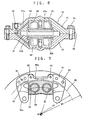
- the disk brake according to the present embodiment includes an integral type caliper 1 comprising an inner portion, an outer portion and a bridge portion 18 connecting the inner and outer portions together.
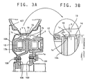
- the inner portion of the caliper has two legs 1a (Fig. 2) secured to a flange 102 of an axle housing as a nonrotating portion of the vehicle by bolts 104 as shown in Fig. 3A.
- the caliper defines a groove 14 in which is received a disk rotor 19 such that the rotor having a radius R3 rotates with a predetermined clearance left between its outer perimeter and the inner wall of the bridge portion 18.
- the disk rotor 19 is secured to a hub flange 106 integral with the wheel axle, not shown, by bolts 109, together with a wheel 108 carrying a tire 107.
- the inner and outer portions of the caliper 1 are formed with cylinders 3 and 2, respectively (Fig. 1).
- the cylinders 3 are through holes having their rear ends closed by threading plugs 4 having hexagonal recesses with O-rings 5 disposed therebetween.
- the cylinders 2 are blind holes formed by a tool inserted through the cylinders 3 before they are closed by the plugs 4. At their rear ends, the cylinders 2 are connected together by a passage 7 formed when the caliper is formed by casting.
- Obligue passages 6a and 6b extend from the backs of the respective cylinders 2 to openings at both ends of the caliper.
- Obligue passages 8a and 8b extend from the backs of the respective cylinders 3 to intermediate portions of the passages 6a and 6b, respectively, to connect the cylinders 3 with the cylinders 2.
- the passages 8a and 8b are formed by a drill inserted in the respective cylinders 3 before they are closed by the plugs 4.
- One of the openings is closed by a plug 9, and to the other opening 10 is connected an external fluid pressure source, not shown, to supply fluid pressure to pistons 12 received in the respective cylinders 2, 3 through the passages 6a, 6b, 8a, 8b and 7.
- Piston seals 11 seal fluid pressure.
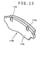
- Friction pads 13a, 13b are disposed between the disk rotor and the pistons on both sides while hanging from pad pins 17 inserted through pin holes 16 formed in the pads (Fig. 2) and secured to the caliper.
- the pistons on both sides are moved toward each other to press the pads 13a, 13b against the rotor, thereby applying braking force to the disk rotor.
- the caliper is formed with torque bearing surfaces 15 at both ends of the pads to bear the braking torque.
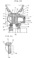
- the wheel clearance is extremely slight at a part 1c of the outer portion close to the disk rotor. Due to the necessity of reducing the thickness of the bridge portion 18 to provide a required wheel clearance, the rigidity of the bridge portion 18 tends to be the lowest at part 1c.
- a recess 1d having an arcuate cross-section having a predetermined radius of curvature R is formed in the groove 14 in the inner surface of the outer portion of the caliper 1 along the outer corner between the outer portion and the bridge portion 18 of the caliper so as to extend in a direction in which the piston moves and not to protrude radially inwardly beyond the inner surface of the bridge portion 18.
- the recess 1d should preferably be formed black by casting because machining would form tool marks on the surface.
- the recess 1d prevents stress concentration on the inner corner between the outer portion and the bridge portion 18 of the caliper. This makes it possible to form the caliper from an aluminum alloy casting instead of steel casting and thus to reduce the weight of the caliper.
- the calipers tested were made of an aluminum alloy for casting known as [Type 4 CH], which is defined under JIS H 2211 and comprises 6.5-7.5 wt% Si, 0.20 wt% or less Ti, 0.15 wt% or less Fe, and Cu, Mg, Ni, etc. with the balance being Al.
- [Type 4 CH] which is defined under JIS H 2211 and comprises 6.5-7.5 wt% Si, 0.20 wt% or less Ti, 0.15 wt% or less Fe, and Cu, Mg, Ni, etc. with the balance being Al.
- Fig. 6 shows the relationship between the average of the stresses measured by the gauges and the input fluid pressure for the caliper having a recess 1d having a radius of curvature R of 8 mm (which means that the R/T ratio is greater than 0.4).
- R/T ratio is greater than 0.4.
- the stress at input pressure 140 kgf/cm 2 is still only 21.7 kgf/mm 2 , which is well within 80% of the maximum allowable stress of [Type 4 CH].
- Fig. 7 shows the relationship between the average of the stresses measured by the gauges and the R/T ratio when the input fluid pressure was 140 kgf/cm 2 .
- the graph clearly shows that the stress increases sharply as the R/T ratio decreases below 0.4. This shows that in order to prevent deflection of the bridge portion 18 near its groove 14, the R/T ratio should be equal to or greater than 0.4.
Landscapes
- Engineering & Computer Science (AREA)
- General Engineering & Computer Science (AREA)
- Mechanical Engineering (AREA)
- Braking Arrangements (AREA)
Claims (5)
- Étrier de frein à disque (1) d'un seul tenant, comprenant une portion intérieure formée avec un premier cylindre (3) et qui peut, en utilisation, être fixée à une partie stationnaire d'un véhicule, une portion extérieure formée avec un second cylindre (2), une portion de pontage (18) qui connecte ladite portion intérieure et ladite portion extérieure, ladite portion de pontage ayant, sur sa surface radialement intérieure, une gorge arquée (14) avec une section transversale définissant un coin extérieur adjacent à ladite portion extérieure et un coin intérieur adjacent à ladite portion intérieure, un piston (12) reçu dans chacun dudit premier et dudit second cylindre, ladite gorge (14) recevant en utilisation une portion périphérique radialement extérieure d'un rotor en disque (19) attaché à une roue du véhicule et positionné, en utilisation, entre lesdits pistons, ledit étrier recevant, en utilisation à un emplacement circonférentiel prédéterminé, des patins de friction (13a, 13b) qui sont disposés, en utilisation, entre ledit rotor en disque et lesdits pistons de façon à être déplaçables en rapprochement et en éloignement dudit rotor en disque, ladite portion intérieure, ladite portion extérieure et ladite portion de pontage étant, en utilisation, axialement immobiles par rapport au rotor en disque, ladite portion de pontage (18) comprenant des tronçons de pontage espacés circonférentiellement sur des côtés opposés dudit emplacement des patins de friction, ladite gorge étant prévue dans lesdits tronçons de pontage,
caractérisé en ce que ladite gorge est formée avec un évidement (1d) ayant une section transversale arquée avec un rayon de courbure prédéterminé, ledit évidement étant prévu au niveau dudit coin extérieur de ladite gorge de façon à s'étendre dans une direction dans laquelle lesdits pistons sont déplacés de manière à ne pas se projeter radialement vers l'intérieur au-delà des surfaces intérieures desdits tronçons de pontage. - Étrier de frein à disque selon la revendication 1, dans lequel ledit évidement est formé borgne par coulée.
- Étrier de frein à disque selon la revendication 1 ou 2, dans lequel le rapport dudit rayon de courbure sur l'épaisseur minimum de ladite portion de pontage est égal ou supérieur à 0,4.
- Étrier de frein à disque selon l'une quelconque des revendications 1 à 3, dans lequel ledit étrier est formé par coulée d'un alliage d'aluminium.
- Frein à disque comprenant un étrier tel que revendiqué dans l'une quelconque des revendications 1 à 4, un rotor en disque positionné entre lesdits pistons, et des patins de friction disposés entre ledit rotor en disque et lesdits pistons.
Applications Claiming Priority (2)
| Application Number | Priority Date | Filing Date | Title |
|---|---|---|---|
| JP20140899 | 1999-07-15 | ||
| JP11201408A JP2001027267A (ja) | 1999-07-15 | 1999-07-15 | キャリパボディ |
Publications (3)
| Publication Number | Publication Date |
|---|---|
| EP1069332A2 EP1069332A2 (fr) | 2001-01-17 |
| EP1069332A3 EP1069332A3 (fr) | 2002-11-20 |
| EP1069332B1 true EP1069332B1 (fr) | 2005-10-12 |
Family
ID=16440600
Family Applications (1)
| Application Number | Title | Priority Date | Filing Date |
|---|---|---|---|
| EP00305559A Expired - Lifetime EP1069332B1 (fr) | 1999-07-15 | 2000-07-03 | Etrier de frein à disque amélioré |
Country Status (4)
| Country | Link |
|---|---|
| US (1) | US6367595B1 (fr) |
| EP (1) | EP1069332B1 (fr) |
| JP (1) | JP2001027267A (fr) |
| DE (1) | DE60023070T2 (fr) |
Families Citing this family (25)
| Publication number | Priority date | Publication date | Assignee | Title |
|---|---|---|---|---|
| WO2002077483A1 (fr) * | 2001-03-27 | 2002-10-03 | Delphi Technologies Inc | Procede et appareil pour la construction d'un frein a disque |
| AUPS066802A0 (en) * | 2002-02-21 | 2002-03-14 | Pbr Australia Pty Ltd | Improved disc brake caliper |
| US7108109B1 (en) | 2003-09-25 | 2006-09-19 | Scott Wilkings | Mono-bloc brake caliper and evaporable pattern for casting same |
| JP2005163809A (ja) | 2003-11-28 | 2005-06-23 | Hitachi Ltd | ディスクブレーキ |
| DE60317117T2 (de) * | 2003-12-30 | 2008-07-31 | Freni Brembo S.P.A., Curno | Bremssattel für eine scheibenbremse |
| US20060124404A1 (en) * | 2004-11-04 | 2006-06-15 | Eduardo Morais | Opposed piston caliper for use in a vehicle disc brake assembly and method for producing same |
| US8672100B2 (en) * | 2005-02-07 | 2014-03-18 | Hitachi, Ltd. | Cylinder apparatus and disk brake |
| JP4823716B2 (ja) * | 2005-02-07 | 2011-11-24 | 日立オートモティブシステムズ株式会社 | ディスクブレーキ |
| EP1904246B1 (fr) * | 2005-06-28 | 2020-01-15 | Freni Brembo S.p.A. | Corps d'étrier de frein à disque, procédé pour sa fabrication par moulage et noyau pour ledit procédé de fabrication par moulage |
| JP4828255B2 (ja) | 2006-02-24 | 2011-11-30 | 日立オートモティブシステムズ株式会社 | ディスクブレーキ |
| DE102007006472A1 (de) * | 2006-04-20 | 2007-11-08 | Continental Teves Ag & Co. Ohg | Scheibenbremse |
| JP4757791B2 (ja) * | 2006-12-28 | 2011-08-24 | 日立オートモティブシステムズ株式会社 | ディスクブレーキのモノブロックキャリパおよびその製造方法 |
| ITMI20071109A1 (it) * | 2007-05-31 | 2008-12-01 | Sunstar Engineering Pte Ltd | "metodo per la fabbricazione di pinze per freni a disco con tappo forzato" |
| DE102008029582A1 (de) * | 2007-10-19 | 2009-04-23 | Continental Teves Ag & Co. Ohg | Scheibenbremse |
| JP4832402B2 (ja) * | 2007-10-22 | 2011-12-07 | 日立オートモティブシステムズ株式会社 | ディスクブレーキおよびディスクブレーキの製造方法 |
| JP4818336B2 (ja) * | 2008-02-20 | 2011-11-16 | 日信工業株式会社 | 車両用ディスクブレーキのキャリパボディ |
| JP5157816B2 (ja) * | 2008-10-21 | 2013-03-06 | 株式会社アドヴィックス | ピストン対向型ディスクブレーキ |
| JP4864986B2 (ja) * | 2009-01-08 | 2012-02-01 | 日信工業株式会社 | ピストン対向型車両用ディスクブレーキ |
| KR101353720B1 (ko) | 2011-06-23 | 2014-01-20 | 허종도 | 제동장치용 캘리퍼 |
| EP2884131B1 (fr) * | 2012-08-10 | 2021-03-03 | Nippon Light Metal Co., Ltd. | Étrier pour freins à disque |
| US8905200B2 (en) | 2012-09-14 | 2014-12-09 | Kenneth Eric Gutelius | Bracketless caliper |
| US10302160B2 (en) * | 2017-04-26 | 2019-05-28 | Akebono Brake Industry Co., Ltd. | Brake caliper assembly |
| TWI752769B (zh) * | 2020-12-25 | 2022-01-11 | 佳鎂科技股份有限公司 | 一體式卡鉗及其製造方法 |
| WO2023040178A1 (fr) * | 2021-09-18 | 2023-03-23 | 奥创动力传动(深圳)有限公司 | Disque de friction et frein |
| US12449010B2 (en) | 2021-09-18 | 2025-10-21 | Altra Industrial Motion (shenzhen) Co., Ltd. | Friction disk and brake |
Citations (2)
| Publication number | Priority date | Publication date | Assignee | Title |
|---|---|---|---|---|
| GB818077A (en) * | 1956-04-10 | 1959-08-12 | Girling Ltd | Improvements relating to disc brakes for vehicles |
| US5433300A (en) * | 1991-09-25 | 1995-07-18 | G.K.N. Sankey Ltd. | Brake caliper |
Family Cites Families (8)
| Publication number | Priority date | Publication date | Assignee | Title |
|---|---|---|---|---|
| AU521333B2 (en) * | 1978-03-01 | 1982-03-25 | Brake And Clutch Industries Australia Pty. Ltd. | Improved disc brake assembly |
| DE3026817A1 (de) * | 1980-07-16 | 1982-02-11 | Alfred Teves Gmbh, 6000 Frankfurt | Schwimmsattel-teilbelagscheibenbremse, insbesondere fuer kraftfahrzeuge |
| GB9001565D0 (en) * | 1990-01-23 | 1990-03-21 | Gen Motors France | Disc brake |
| GB9305795D0 (en) * | 1993-03-19 | 1993-05-05 | Automotive Products Plc | A brake disc |
| JP3518054B2 (ja) * | 1995-05-26 | 2004-04-12 | 住友電気工業株式会社 | ディスクブレーキ用制振装置 |
| DE69605483T2 (de) * | 1995-06-13 | 2000-07-27 | Sumitomo Electric Industries, Ltd. | Scheibenbremse mit Schwingungsdämpfer |
| JPH1163041A (ja) | 1997-08-27 | 1999-03-05 | Nissin Kogyo Kk | 車両用ディスクブレーキのキャリパボディ |
| US6000506A (en) * | 1998-02-23 | 1999-12-14 | General Motors Corporation | Disc brake caliper |
-
1999
- 1999-07-15 JP JP11201408A patent/JP2001027267A/ja active Pending
-
2000
- 2000-07-03 EP EP00305559A patent/EP1069332B1/fr not_active Expired - Lifetime
- 2000-07-03 DE DE60023070T patent/DE60023070T2/de not_active Expired - Fee Related
- 2000-07-06 US US09/610,956 patent/US6367595B1/en not_active Expired - Fee Related
Patent Citations (2)
| Publication number | Priority date | Publication date | Assignee | Title |
|---|---|---|---|---|
| GB818077A (en) * | 1956-04-10 | 1959-08-12 | Girling Ltd | Improvements relating to disc brakes for vehicles |
| US5433300A (en) * | 1991-09-25 | 1995-07-18 | G.K.N. Sankey Ltd. | Brake caliper |
Also Published As
| Publication number | Publication date |
|---|---|
| DE60023070T2 (de) | 2006-06-22 |
| JP2001027267A (ja) | 2001-01-30 |
| EP1069332A2 (fr) | 2001-01-17 |
| DE60023070D1 (de) | 2005-11-17 |
| US6367595B1 (en) | 2002-04-09 |
| EP1069332A3 (fr) | 2002-11-20 |
Similar Documents
| Publication | Publication Date | Title |
|---|---|---|
| EP1069332B1 (fr) | Etrier de frein à disque amélioré | |
| US6116384A (en) | Disk brake | |
| EP2022999B2 (fr) | Corps de compas de frein à disque et compas de frein à disque comportant un tel corps | |
| US9222532B2 (en) | Brake carrier | |
| EP0747608B1 (fr) | Frein à disque | |
| US20060054425A1 (en) | Floating caliper-type disc brake | |
| WO2007087393A2 (fr) | Machoire de frein symetrique | |
| EP1462671A1 (fr) | Etrier coulissant monopièce pour un frein | |
| US6000506A (en) | Disc brake caliper | |
| CN110088495A (zh) | 对置活塞型盘式制动器用卡钳 | |
| EP1586787A1 (fr) | Etrier coulissant monobloc. | |
| GB2085101A (en) | Light weight disc brake caliper | |
| US20090145702A1 (en) | Brake pad for a vehicle disc brake assembly | |
| US4762206A (en) | Disc brake | |
| US4094389A (en) | Disc brakes | |
| EP3680502B1 (fr) | Étrier pour frein à disque de type à piston opposé | |
| EP0062403B1 (fr) | Etrier pour freins à disques | |
| JP2002213502A (ja) | 車両用ディスクブレーキのキャリパボディ | |
| JPH06341470A (ja) | ディスクブレーキの対向ピストン型キャリパ | |
| JPH1163041A (ja) | 車両用ディスクブレーキのキャリパボディ | |
| US5167303A (en) | Disc brake | |
| JP4076750B2 (ja) | 対向ピストン型ディスクブレーキ | |
| JP4718422B2 (ja) | ディスクブレーキ | |
| JPH081304Y2 (ja) | ディスクブレーキ | |
| EP1091138A2 (fr) | Cylindre pour frein à disque |
Legal Events
| Date | Code | Title | Description |
|---|---|---|---|
| PUAI | Public reference made under article 153(3) epc to a published international application that has entered the european phase |
Free format text: ORIGINAL CODE: 0009012 |
|
| AK | Designated contracting states |
Kind code of ref document: A2 Designated state(s): AT BE CH CY DE DK ES FI FR GB GR IE IT LI LU MC NL PT SE |
|
| AX | Request for extension of the european patent |
Free format text: AL;LT;LV;MK;RO;SI |
|
| PUAL | Search report despatched |
Free format text: ORIGINAL CODE: 0009013 |
|
| AK | Designated contracting states |
Kind code of ref document: A3 Designated state(s): AT BE CH CY DE DK ES FI FR GB GR IE IT LI LU MC NL PT SE |
|
| AX | Request for extension of the european patent |
Free format text: AL;LT;LV;MK;RO;SI |
|
| 17P | Request for examination filed |
Effective date: 20030211 |
|
| AKX | Designation fees paid |
Designated state(s): DE GB |
|
| 17Q | First examination report despatched |
Effective date: 20040211 |
|
| GRAP | Despatch of communication of intention to grant a patent |
Free format text: ORIGINAL CODE: EPIDOSNIGR1 |
|
| RTI1 | Title (correction) |
Free format text: IMPROVED DISK BRAKE CALIPER |
|
| GRAS | Grant fee paid |
Free format text: ORIGINAL CODE: EPIDOSNIGR3 |
|
| GRAA | (expected) grant |
Free format text: ORIGINAL CODE: 0009210 |
|
| AK | Designated contracting states |
Kind code of ref document: B1 Designated state(s): DE GB |
|
| REG | Reference to a national code |
Ref country code: GB Ref legal event code: FG4D |
|
| REF | Corresponds to: |
Ref document number: 60023070 Country of ref document: DE Date of ref document: 20051117 Kind code of ref document: P |
|
| PLBE | No opposition filed within time limit |
Free format text: ORIGINAL CODE: 0009261 |
|
| STAA | Information on the status of an ep patent application or granted ep patent |
Free format text: STATUS: NO OPPOSITION FILED WITHIN TIME LIMIT |
|
| 26N | No opposition filed |
Effective date: 20060713 |
|
| PGFP | Annual fee paid to national office [announced via postgrant information from national office to epo] |
Ref country code: GB Payment date: 20070627 Year of fee payment: 8 |
|
| PGFP | Annual fee paid to national office [announced via postgrant information from national office to epo] |
Ref country code: DE Payment date: 20080711 Year of fee payment: 9 |
|
| GBPC | Gb: european patent ceased through non-payment of renewal fee |
Effective date: 20080703 |
|
| PG25 | Lapsed in a contracting state [announced via postgrant information from national office to epo] |
Ref country code: GB Free format text: LAPSE BECAUSE OF NON-PAYMENT OF DUE FEES Effective date: 20080703 |
|
| PG25 | Lapsed in a contracting state [announced via postgrant information from national office to epo] |
Ref country code: DE Free format text: LAPSE BECAUSE OF NON-PAYMENT OF DUE FEES Effective date: 20100202 |