EP1069280A1 - Procédé et dispositif pour le forage d'un tunnel ou d'une galerie et élément pour leur utilisation - Google Patents
Procédé et dispositif pour le forage d'un tunnel ou d'une galerie et élément pour leur utilisation Download PDFInfo
- Publication number
- EP1069280A1 EP1069280A1 EP00890216A EP00890216A EP1069280A1 EP 1069280 A1 EP1069280 A1 EP 1069280A1 EP 00890216 A EP00890216 A EP 00890216A EP 00890216 A EP00890216 A EP 00890216A EP 1069280 A1 EP1069280 A1 EP 1069280A1
- Authority
- EP
- European Patent Office
- Prior art keywords
- support plate
- component
- components
- ring
- tunnel
- Prior art date
- Legal status (The legal status is an assumption and is not a legal conclusion. Google has not performed a legal analysis and makes no representation as to the accuracy of the status listed.)
- Withdrawn
Links
- 238000000034 method Methods 0.000 title claims abstract description 33
- 239000004567 concrete Substances 0.000 claims abstract description 21
- 239000000463 material Substances 0.000 claims abstract description 15
- 230000002787 reinforcement Effects 0.000 claims description 30
- 238000009434 installation Methods 0.000 claims description 19
- 238000010276 construction Methods 0.000 claims description 14
- 238000009412 basement excavation Methods 0.000 claims description 9
- 230000005641 tunneling Effects 0.000 claims description 8
- 210000000078 claw Anatomy 0.000 claims description 5
- 238000004519 manufacturing process Methods 0.000 claims description 5
- 239000011150 reinforced concrete Substances 0.000 claims description 4
- 230000003014 reinforcing effect Effects 0.000 claims description 4
- 239000002689 soil Substances 0.000 claims description 3
- 239000000853 adhesive Substances 0.000 claims description 2
- 230000001070 adhesive effect Effects 0.000 claims description 2
- 230000000694 effects Effects 0.000 claims 1
- 230000015572 biosynthetic process Effects 0.000 abstract 2
- 229910000831 Steel Inorganic materials 0.000 description 5
- 239000010959 steel Substances 0.000 description 5
- 238000005065 mining Methods 0.000 description 4
- 230000001419 dependent effect Effects 0.000 description 3
- XLYOFNOQVPJJNP-UHFFFAOYSA-N water Substances O XLYOFNOQVPJJNP-UHFFFAOYSA-N 0.000 description 2
- 229910001294 Reinforcing steel Inorganic materials 0.000 description 1
- 230000000712 assembly Effects 0.000 description 1
- 238000000429 assembly Methods 0.000 description 1
- 239000004568 cement Substances 0.000 description 1
- 230000008878 coupling Effects 0.000 description 1
- 238000010168 coupling process Methods 0.000 description 1
- 238000005859 coupling reaction Methods 0.000 description 1
- 230000002996 emotional effect Effects 0.000 description 1
- 238000009415 formwork Methods 0.000 description 1
- 239000003673 groundwater Substances 0.000 description 1
- 239000011178 precast concrete Substances 0.000 description 1
- 230000001681 protective effect Effects 0.000 description 1
- 238000005086 pumping Methods 0.000 description 1
- 238000007789 sealing Methods 0.000 description 1
- 239000002002 slurry Substances 0.000 description 1
- 210000003462 vein Anatomy 0.000 description 1
Images


Classifications
-
- E—FIXED CONSTRUCTIONS
- E21—EARTH OR ROCK DRILLING; MINING
- E21D—SHAFTS; TUNNELS; GALLERIES; LARGE UNDERGROUND CHAMBERS
- E21D11/00—Lining tunnels, galleries or other underground cavities, e.g. large underground chambers; Linings therefor; Making such linings in situ, e.g. by assembling
- E21D11/04—Lining with building materials
- E21D11/10—Lining with building materials with concrete cast in situ; Shuttering also lost shutterings, e.g. made of blocks, of metal plates or other equipment adapted therefor
- E21D11/105—Transport or application of concrete specially adapted for the lining of tunnels or galleries ; Backfilling the space between main building element and the surrounding rock, e.g. with concrete
-
- E—FIXED CONSTRUCTIONS
- E21—EARTH OR ROCK DRILLING; MINING
- E21D—SHAFTS; TUNNELS; GALLERIES; LARGE UNDERGROUND CHAMBERS
- E21D11/00—Lining tunnels, galleries or other underground cavities, e.g. large underground chambers; Linings therefor; Making such linings in situ, e.g. by assembling
- E21D11/04—Lining with building materials
- E21D11/08—Lining with building materials with preformed concrete slabs
-
- E—FIXED CONSTRUCTIONS
- E21—EARTH OR ROCK DRILLING; MINING
- E21D—SHAFTS; TUNNELS; GALLERIES; LARGE UNDERGROUND CHAMBERS
- E21D9/00—Tunnels or galleries, with or without linings; Methods or apparatus for making thereof; Layout of tunnels or galleries
- E21D9/06—Making by using a driving shield, i.e. advanced by pushing means bearing against the already placed lining
- E21D9/0607—Making by using a driving shield, i.e. advanced by pushing means bearing against the already placed lining the shield being provided with devices for lining the tunnel, e.g. shuttering
Definitions
- the invention relates to a method and a device for advancing and to expand tunnels and tunnels, especially in unsustainable floor with the characteristics of the introductory parts of the Main procedural claim or main device claim.
- the invention further relates to (prefabricated) components that are used when executing of the method according to the invention can be used, and the with the device according to the invention for expanding the tunnel can be processed.
- the tunneling shield is equipped with a feed device, for example a piston-cylinder arrangement, which is located on the supports the tunnel construction that has already been produced, driven forward. While the tunneling is carried out in the space between tunnel expansion and excavation a hardening mass, such as concrete, is pressed in.
- AT 399 203 B (Mayreder) is a device for advancing known from tunnels and tunnels, in the protection of the shield tail Prefabricated segments are attached. The space between that Eruption and tunnel expansion becomes with a plastically deformable and filled in non-compressible material. This leaves controlled Mountain deformations too.
- segment building blocks are used for the interior used with a hydraulic mounting device be installed, and which are to be coupled individually.
- Disadvantage of this The procedure is that for the installation and coupling of the finished parts multiple operations are required and that the procedure therefore time consuming, difficult to fully automate and computer control is.
- a device is known from EP 132 066 A1 (Mini Tunnels Int. Ltd) known in which finished parts are assembled into a ring, placed on a tube from behind and pushed forward with presses become. At the same time, the gap between the breakout area and built-in tunnel pipes, via a pipe with hardening mass filled out.
- the disadvantage of this procedure is that with larger ones Construction sections a backfill material that does not solidify over a long period of time must be used, otherwise due to the increasing skin friction advancing the tunnel tube, and inserting the Filling material is not possible. If a material is used that remains plastic for a long time, there is a risk of sinking and the deformation of the tube when loaded inside the tube. On Another problem is the difficult controllability of the jacking over longer distances.
- a tunnel construction device is known from FR 2 585 067 A (GTM), where the excavation diameter is only slightly larger than that Outside diameter of the finished tunnel expansion. On completing the The space between the excavation and tunnel expansion is dispensed with. The device is supported in the stem with hydraulic presses on the existing expansion.
- the object of the invention is a method and an apparatus for Manufacture to create tunnel tubes, taking the structure of the material around the tunnel tube is not changed, by simple Processes a fully automatic, computer-controlled work is possible, and with a stable tunnel tube in one work step can be manufactured.
- tunnels and tunnels can be driven and removed quickly and safely can.
- An advantage of the device according to the invention is that it is simple is set up and operated fully automatically without difficulty can be.
- the component according to the invention has the advantage that it is inexpensive as a prefabricated component and in series, possibly also automated can be manufactured.
- the inventive Procedure with a tunneling shield (outer support shield), the one is essentially tubular component, worked on its rear end with an inner support shield that is also a tubular component is overlapped.
- the inner support shield supports the components while they are assembled into a ring by Hardening of the components inserted between the excavation and the ring hardening mass (concrete).
- the installation device provided in the device according to the invention consists in one embodiment of a rotatable Ein> construction ring and one provided at the front end of the inner support shield Built-in table. With this built-in table, in one embodiment the components that can be precast reinforced concrete components through an opening at the front end of the inner support shield the mounting ring. Then the mounting ring is one step ) turned further and the next component placed on the mounting ring, until a ring of components is closed. To do this is in one Embodiment of the mounting ring rotatable with a motor.
- the next step is the piston-cylinder arrangements again retracted so that the inner support plate and the built-in car be moved forward until they have reached the position in which the next ring can be made from components.
- the invention has Device as essential components an outer support plate, the front end formed for example as an oblique cutting ring is known at the front end of the outer support plate Devices for removing material may be provided can.
- Another component of the device according to the invention in a preferred embodiment is the inner support shield, which in any relative position between the outer support plate and the inner support plate this overlaps and serves as a temporary support for serves the tunnel construction made of components.
- the inside Support plate is a built-in table with which, for example Components fed via feed rails onto the mounting ring, which in the rear end of the outer support plate is rotatably supported, removable are.
- linear motors especially piston-cylinder arrangements, e.g. can be operated hydraulically, provided which, for example, has a flange at the front end of the inner support shield on the tunnel construction already made Support components.
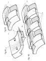
- the components that can be used in the context of the invention are in particular Prefabricated components made of reinforced concrete, which is an essentially circular sector Have cross-sectional shape. Point on the outside these components are preferably diagonally opposite to each other Open recesses (recesses) on the edge, in which the reinforcement exposed, the reinforcement both in the circumferential direction (transversely to the axis of the curvature of the components), as well as in the axial direction (in Reinforcement bars aligned in the direction of the axis of the curvature of the components) are provided. Both those running in the circumferential direction Reinforcement bars, as well as those running in the axial direction Reinforcing bars are above the components in next to the recesses lying areas above.
- first special component which as first component is inserted in the mounting ring
- second Special component which is the last component in the otherwise completed ring of components is used.
- the latter has mutually parallel, in the direction of the axis of curvature aligned side walls.
- components 15 are preferably prefabricated reinforced concrete components, which, as will be described below will be assembled into rings with the mounting device and which is the supporting structure of the tunnel tube, i.e. the tunnel expansion 9 form.
- the components 15 can in precast concrete plants manufactured and transported with vehicles.
- the entire reinforcement 17 of the tunnel extension 9 is arranged.
- the reinforcement 17 projects on one long side (in Direction of the axis of the curvature of the component) and a broad side (transverse to the axis of curvature of the component Side) on the adhesive length of the steel out of component 15.
- On the opposite side in the outside is each Component 15 provided a recess.
- the reinforcement 17 extends only to the edge of the component 15, but has from Bottom of the recess a distance.
- the bars of the reinforcement 17 in longitudinal and in Cross direction by length of detention. This is shown in Figure 10.
- Fig. 10 shows that the bars of the reinforcement 17 in each other in the area 18 in Overlap lengthwise. This creates a continuous reinforcement network, by the measures described below with hardening Mass, e.g. is covered with concrete.
- FIG. 11 shows a special component 15, which is the first component 15 is used in the manufacture of a ring from components 15.
- this component 15 according to FIG. 11 is only one on the outside Provided depression and the rods extending in the circumferential direction the reinforcement protrude over the component 15 on both sides.
- the longitudinal reinforcement bars of reinforcement 17 are only on the opposite side of the recess Component 15 according to FIG. 11.
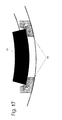
- FIG. 12 The special component shown in FIG. 12 is shown in FIG used the ring.
- this component 15 there are only those in the longitudinal direction, reinforcement bars running in the direction of the tunnel axis the reinforcement 17 - but not the ones running in the circumferential direction Reinforcing bars - on one side over component 15 about.
- This component 15 has three recesses on its outside on and the circumferential bars of the reinforcement 17th stand over the surfaces of the component running parallel to the axis 14 not over. It is also envisaged that the first and the penultimate Component 15 (the components labeled "1" and "15" in FIG.
- the device according to the invention has an outer support plate 3, which is a tubular steel construction, which during the stem Earth pressure picks up and what parts of the mounting device for the Components 15 carries.
- an outer support plate 3 On the front end of the outer support plate 3 a dismantling head 1 can be attached.
- the mining head 1 is in the embodiment executed as an oblique cutting ring, so that this in particular can be used in soft, unsustainable soil.
- the angle of the bevel is chosen so that no material of the floor can break out of the upper area.
- the earth material in mining area 2 with a construction machine can be excavated with the help of conveyor belts and / or vehicles be transported out of the tube. When digging is not about the imaginary extension of the outer surface of the outer Dig out support plate 3 so that behind the outer support plate 3 no voids are created. So it should be the earth material on outer support plate 3 should be as snug as possible from all sides.
- the outer support plate 3 is used of feed devices, for example hydraulic cylinders 4 are continuously advanced. This creates 2 in mining area no area that could break in, since the outer support plate 3 Earth material supports.
- the outer support plate 3 is set up and controlled also via the feed devices 4, in which shown Embodiment three feed devices 4 in the form of hydraulic cylinders are provided. These hydraulic cylinders 4 are arranged evenly over the circumference of the outer support plate 3 and connected to it.
- the hydraulic cylinders 4 are optionally available same pressure and speed or different Pressure and extendable at different speeds.
- the hydraulic cylinders 4 are supported on the front end of a inner support plate 8 via a provided there, to the outside protruding ring flange.
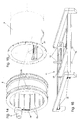
- the front end of the inner support shield 8 is shown in FIG. 15.
- the inner support plate 8 can be a steel pipe.
- the inner support plate 8 carries parts of the mounting device for the Components 15 and it serves as protective formwork during work.
- a rectangular recess 22 is provided behind the flange the components 15 in an installation ring 6 during installation (FIG. 14) are lowerable.
- the advance in turn can also be controlled depending on the concrete pressure. If for example, the specified concrete pressure is no longer maintained can be because of voids in the material or depressions on the Are to be filled on the outside of the components 15, the feed, preferably automatic, slowed down or completely interrupted.
- the concrete 16 is pumped in via a concrete pump via concrete lines 7 and via lines in the rear section of the outer support plate 3 in the space between those assembled for tunnel expansion 9 Components 15 and the outbreak.
- the pressure of the concrete 16 is chosen when pumping in that the Earth pressure, which is initially borne by the outer support plate 3, from Concrete pressure is collected. So is in the area behind that rear end of the outer support plate 3 ensures that in no phase of the excavation is free and can collapse.
- Ingressing groundwater or water from mining area 2 longitudinal water veins is through the cross shield 10 in the area shut off in front of the mounting ring 6 and can be pumped out be pumped into the tunnel tube.
- concrete pipes 23 be provided on the inner surface of the outer support plate 3 flow out. This prevents the concrete pressure behind the outer support plate 3 suddenly drops when the outer support plate 3 in its forward movement recesses on the outside of the Components 15 releases. It is preferred that 15 per component lateral concrete lines 23 are provided.
- Leakage of concrete 16 or cement slurry in the area of the mounting ring 6 can by appropriate sealing measures on the outside Support shield 3 in front of the side concrete lines 23 prevented become.
- the concrete line 7 is in the inner support plate 8 in the direction of Longitudinally movably supported, since the inner support plate 8 independently can be moved from the outer support plate 3.
- the administration 7 is connected to an annular channel in the outer support plate 3, from which several axial lines (channels) leading to the rear Guide end of support plate 3, go out.
- the inner support plate 8 from the area of the Recess 22 through the components 15 placed in the mounting ring 6 have a slightly smaller diameter so that the Movements are easy to perform.
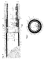
- Fig. 1 shows the outer support plate 3 in the position (retracted Hydraulic cylinder 4) in which the installation of a ring of components 15 is carried out.
- the hydraulic cylinders 4 are in this position retracted so that the inner support plate 8 with its ring flange maximally retracted into the rear end of the outer support plate 3 is.
- the pistons of the hydraulic cylinder 4 are with the flange of the inner support shield 8 connected tensile and pressure resistant.
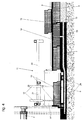
- Fig. 3 shows the position of the outer support plate on a larger scale 3 and the inner support plate 8 of FIG. 1 again.
- Fig. 3 also shows a built-in table 11 on the inner support plate 8 is constructed, and is located above the mounting ring 6.
- the built-in table 11 is shown again in an oblique view in FIG. 16. With the help of the built-in table 11, components 15 are placed over feed rails 14 can be brought up to the built-in table 11 from Built-in table 11 taken over.
- feed rails 14 An exemplary embodiment for the feed rails 14 is shown in FIG. 17 shown. These feed rails 14 have rollers for supporting the components 15 to be conveyed from below and lateral guide rollers, which attack on the side surfaces of the components 15.
- the built-in table 11 consists of a frame construction with two Rails 20 in which a built-in carriage 21 can be moved on rollers is led.
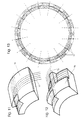
- the mounting ring 16 consists of a steel tube, which is dimensioned so that it can accommodate a complete ring of components 15.
- An end flange of the mounting ring 6 has a ring gear 24 inside provided with which a pinion of a gear motor 5 meshes, so that the mounting ring 6 can be rotated (in writing).
- the mounting ring 6 is via rollers 28 in grooves in the inside of the outer support plate 3 rotatably mounted. There are two rows of rollers 28 intended.
- On the inner surface of the mounting ring 6 are wedge-shaped Guide rails 25 attached to the lateral sliding of Prevent components 15 and an exact fit in the mounting ring 6th manufactured new ring from components 15 with an already installed Secure ring from components 15.
- V-shaped cutouts are provided through which the ribs 25 pass, if the inner support plate 8 is relative to the mounting ring 6 emotional.
- Fig. 3 When inserting components 15 in the mounting ring 6 is as in following described with reference to FIGS. 3 to 7, proceeded.
- Fig. 3 is shown that the inner support plate 8 in its foremost Position is and the hydraulic cylinders 4 are fully retracted.
- the Components 15 are on the feed rails 14 to under the built-in table 11 moves.
- the installation car 21 of the installation table 11 is moved over a component 15 lying at the end of the feed rails 14.
- the component 15 is received with the lifting claws 13 and raised by actuating the cylinder 12.
- the built-in car 21 together with the component 15 into the mounting ring 6 moved forward and the component 15 then through the rectangular Recess 22 of the inner support plate 8 on the mounting ring 6 lowered (Fig. 4).
- the lifting claws 13 are released from the component 15, raised, and the built-in cart 21 moved back so that it could be received of the next component 15 is ready. Then the mounting ring 6 rotated one position with the help of the geared motor 5, so that it is in the position for receiving the next component 15 correct position.
- FIG. 13 also shows that those labeled "1" and "15" in FIG. 13 Components on their side that correspond to the last component 15 according to FIG. 12 are more inclined than the components according to FIG. 8 and 9 and that the component according to FIG. 12 parallel side surfaces has so that it can be used.
- Fig. 13 shows a cross section of an assembled ring Components 15, the dashed lines the necessary alignment the side faces of the components 15 show.
- the thin lines show the ring reinforcement 17 and its lateral protrusions.
- the Numbers "1" to "16" entered in the components indicate the sequence the installation of components 15.
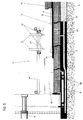
- Fig. 5 shows how by extending the hydraulic cylinder 4 of the Ring of components 15 from the flange at the front end of the inner Support shield 8 from the tunnel construction 9 already made Components 15 is added.
- the longitudinal reinforcements of the components 15 overlap by sticking length, which also means in the longitudinal direction of the tunnel extension 9 a continuous reinforcement is created.
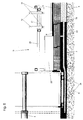
- Fig. 6 shows how from this point in time by further extending the hydraulic cylinder 4 pushed the outer support plate 3 further becomes.
- Fig. 7 shows how by pulling the hydraulic cylinder 4 that inner support plate 8 is tightened, etc. until the recess 22 again at the front end of the inner support plate 8 the mounting ring 6 comes to rest, so that with the manufacture of the next ring of components 15 can be started.
- an embodiment of the invention can be as follows being represented:
- an installation device comes with a Installation ring 6 for use, with which the finished parts 15 mechanically assembled into a ring and attached to the tunnel tube 9.
- a steel tube construction is used as the outer support shield 3 for the propulsion used, which is driven with hydraulic presses 4, while earth material is being excavated inside the pipe.
- the Hydraulic presses 4 are based on the already assembled Tunnel expansion 9 from.
- the finished parts 15 are each on the front End of the tunnel expansion 9 put on.
- the areas of the overlapping Reinforcement, and the cavity behind the outer support shield 3 are pressed out with concrete.
Landscapes
- Engineering & Computer Science (AREA)
- Mining & Mineral Resources (AREA)
- Structural Engineering (AREA)
- Architecture (AREA)
- Life Sciences & Earth Sciences (AREA)
- General Life Sciences & Earth Sciences (AREA)
- Geochemistry & Mineralogy (AREA)
- Geology (AREA)
- Civil Engineering (AREA)
- Environmental & Geological Engineering (AREA)
- Lining And Supports For Tunnels (AREA)
Applications Claiming Priority (2)
| Application Number | Priority Date | Filing Date | Title |
|---|---|---|---|
| AT121199 | 1999-07-13 | ||
| AT121199 | 1999-07-13 |
Publications (1)
| Publication Number | Publication Date |
|---|---|
| EP1069280A1 true EP1069280A1 (fr) | 2001-01-17 |
Family
ID=3509030
Family Applications (1)
| Application Number | Title | Priority Date | Filing Date |
|---|---|---|---|
| EP00890216A Withdrawn EP1069280A1 (fr) | 1999-07-13 | 2000-07-12 | Procédé et dispositif pour le forage d'un tunnel ou d'une galerie et élément pour leur utilisation |
Country Status (1)
| Country | Link |
|---|---|
| EP (1) | EP1069280A1 (fr) |
Citations (7)
| Publication number | Priority date | Publication date | Assignee | Title |
|---|---|---|---|---|
| US4091630A (en) * | 1977-05-03 | 1978-05-30 | Kubota, Ltd. | Intermediate sleeve for installing pipeline by propelling pipes underground |
| EP0132066A1 (fr) | 1983-06-27 | 1985-01-23 | Rees Construction Services Limited | Construction de tunnels et équipement de revêtement de tunnels |
| DE3515680A1 (de) * | 1983-09-07 | 1986-11-06 | Dyckerhoff & Widmann AG, 8000 München | Verfahren zum herstellen eines roehrenfoermigen unterirdischen hohlraums, z. b. einer rohrleitung, sowie vorrichtung zum durchfuehren des verfahrens |
| FR2585067A1 (fr) | 1985-07-19 | 1987-01-23 | Gtm Ets Sa | Bouclier de creusement de galeries souterraines a grande profondeur |
| AT399203B (de) | 1992-05-29 | 1995-04-25 | Mayreder Kraus & Co Ing | Vorrichtung zum vortreiben von tunnel und stollen |
| US5846027A (en) * | 1996-02-22 | 1998-12-08 | Toyo Technos Co., Ltd. | Semi-shield method and apparatus for the same |
| EP0897050A1 (fr) * | 1997-08-14 | 1999-02-17 | I.T.M. Industriele Tunnelbouw Methode C.V. | Procédé de construction d'un tunnel à revêtement |
-
2000
- 2000-07-12 EP EP00890216A patent/EP1069280A1/fr not_active Withdrawn
Patent Citations (8)
| Publication number | Priority date | Publication date | Assignee | Title |
|---|---|---|---|---|
| US4091630A (en) * | 1977-05-03 | 1978-05-30 | Kubota, Ltd. | Intermediate sleeve for installing pipeline by propelling pipes underground |
| EP0132066A1 (fr) | 1983-06-27 | 1985-01-23 | Rees Construction Services Limited | Construction de tunnels et équipement de revêtement de tunnels |
| US4594025A (en) * | 1983-06-27 | 1986-06-10 | Rees Construction Services Limited | Tunnelling and tunnel relining equipment |
| DE3515680A1 (de) * | 1983-09-07 | 1986-11-06 | Dyckerhoff & Widmann AG, 8000 München | Verfahren zum herstellen eines roehrenfoermigen unterirdischen hohlraums, z. b. einer rohrleitung, sowie vorrichtung zum durchfuehren des verfahrens |
| FR2585067A1 (fr) | 1985-07-19 | 1987-01-23 | Gtm Ets Sa | Bouclier de creusement de galeries souterraines a grande profondeur |
| AT399203B (de) | 1992-05-29 | 1995-04-25 | Mayreder Kraus & Co Ing | Vorrichtung zum vortreiben von tunnel und stollen |
| US5846027A (en) * | 1996-02-22 | 1998-12-08 | Toyo Technos Co., Ltd. | Semi-shield method and apparatus for the same |
| EP0897050A1 (fr) * | 1997-08-14 | 1999-02-17 | I.T.M. Industriele Tunnelbouw Methode C.V. | Procédé de construction d'un tunnel à revêtement |
Similar Documents
| Publication | Publication Date | Title |
|---|---|---|
| DE3043312A1 (de) | Verfahren und vorrichtung zum vortrieb einer gleitschalung | |
| DE2550050C2 (de) | Einrichtung zum Auffahren von Tunnels o.dgl. mittels eines Verbauschildes unter Einbringen einer Ortbetonauskleidung | |
| DE69310411T2 (de) | Gerät zum Graben von Tunneln | |
| DE2108591C3 (de) | Einrichtung und Verfahren zur Durchführung der Schildbauweise für die Errichtung von Tunnels und Stollen | |
| CH646490A5 (de) | Verfahren und vorrichtung zum einbringen einer betonauskleidung beim vortrieb unterirdischer hohlraeume. | |
| DE2739079A1 (de) | Verfahren zur herstellung eines tunnels mit unterteiltem querschnitt | |
| DE3521888C2 (fr) | ||
| DE2706244C2 (de) | Messervortriebsverfahren und Messer zum Vortrieb von Tunneln, Stollen u.dgl. unter gleichzeitigem Einbringen einer Betonauskleidung | |
| DE2505980A1 (de) | Verfahren zum vortrieb von im wesentlichen ringfoermigen bauteilen, insbesondere fuer den hoch- und tiefbau | |
| AT396505B (de) | Verfahren und vorrichtung zur unterirdischen herstellung von kanälen, stollen od.dgl. | |
| EP1069280A1 (fr) | Procédé et dispositif pour le forage d'un tunnel ou d'une galerie et élément pour leur utilisation | |
| DE2450281A1 (de) | Vorrichtung zum fortschreitenden aushub und verbau offener baugraeben und verfahren dazu | |
| DE3520092C2 (fr) | ||
| DE2109384C3 (de) | Verfahren und Vorrichtung zum Herstellen röhrenförm iger Tunnel, Stollen od.dgl. im Schildvortrieb mit einer Auskleidung aus Ortbeton | |
| DE3244040C2 (fr) | ||
| DE2622202C2 (de) | Verfahren und Einrichtung zum Auffahren eines tiefen Grabens im Messerschildverfahren, insbesondere für die Errichtung von Tunnelbauwerken | |
| DE2558670A1 (de) | Vortriebsmesser fuer einen verbauschild und verfahren zum einbringen eines ortbetonausbaus beim auffahren von tunneln, stollen o.dgl. mittels eines verbauschildes | |
| DE2555524C2 (de) | Vortriebsmesser für einen Verbauschild | |
| DE2109383C2 (de) | Verfahren zum unterirdischen Auffahren und sofortigen Auskleiden von Tunneln, Stollen od. dgl | |
| DE1187658B (de) | Verfahren zum unterirdischen Herstellen von Tunnels, Stollen oder aehnlichen langgestreckten Bauwerken unter Verwendung eines Vortriebsschildes | |
| DE2605741A1 (de) | Verbauschild und verfahren zum auffahren eines tunnels, stollens, grabens o.dgl. unter verwendung eines verbauschildes | |
| DE838276C (de) | Teleskopierverfahren zum Vortrieb eines Hohlkoerpers in beliebiger Richtung | |
| DE1658751C (de) | Verfahren zum Herstellen von Tunnels, Stollen od. dgl. in Gebirgen mit Zonen wechselnder Standfestigkeit sowie Vorrichtung zur Durchführung des Verfahrens | |
| DE2531007C3 (de) | Verfahren und Vorrichtung zur Erstellung von Arbeitsschächten innerhalb im Schildvortrieb aufgefahrener Gräben | |
| DE3609791C2 (fr) |
Legal Events
| Date | Code | Title | Description |
|---|---|---|---|
| PUAI | Public reference made under article 153(3) epc to a published international application that has entered the european phase |
Free format text: ORIGINAL CODE: 0009012 |
|
| AK | Designated contracting states |
Kind code of ref document: A1 Designated state(s): AT BE CH CY DE DK ES FI FR GB GR IE IT LI LU MC NL PT SE |
|
| AX | Request for extension of the european patent |
Free format text: AL;LT;LV;MK;RO;SI |
|
| AKX | Designation fees paid | ||
| REG | Reference to a national code |
Ref country code: DE Ref legal event code: 8566 |
|
| STAA | Information on the status of an ep patent application or granted ep patent |
Free format text: STATUS: THE APPLICATION IS DEEMED TO BE WITHDRAWN |
|
| 18D | Application deemed to be withdrawn |
Effective date: 20010718 |