EP1069280A1 - Method and device for driving a tunnel or gallery and element for their use - Google Patents
Method and device for driving a tunnel or gallery and element for their use Download PDFInfo
- Publication number
- EP1069280A1 EP1069280A1 EP00890216A EP00890216A EP1069280A1 EP 1069280 A1 EP1069280 A1 EP 1069280A1 EP 00890216 A EP00890216 A EP 00890216A EP 00890216 A EP00890216 A EP 00890216A EP 1069280 A1 EP1069280 A1 EP 1069280A1
- Authority
- EP
- European Patent Office
- Prior art keywords
- support plate
- component
- components
- ring
- tunnel
- Prior art date
- Legal status (The legal status is an assumption and is not a legal conclusion. Google has not performed a legal analysis and makes no representation as to the accuracy of the status listed.)
- Withdrawn
Links
- 238000000034 method Methods 0.000 title claims abstract description 33
- 239000004567 concrete Substances 0.000 claims abstract description 21
- 239000000463 material Substances 0.000 claims abstract description 15
- 230000002787 reinforcement Effects 0.000 claims description 30
- 238000009434 installation Methods 0.000 claims description 19
- 238000010276 construction Methods 0.000 claims description 14
- 238000009412 basement excavation Methods 0.000 claims description 9
- 230000005641 tunneling Effects 0.000 claims description 8
- 210000000078 claw Anatomy 0.000 claims description 5
- 238000004519 manufacturing process Methods 0.000 claims description 5
- 239000011150 reinforced concrete Substances 0.000 claims description 4
- 230000003014 reinforcing effect Effects 0.000 claims description 4
- 239000002689 soil Substances 0.000 claims description 3
- 239000000853 adhesive Substances 0.000 claims description 2
- 230000001070 adhesive effect Effects 0.000 claims description 2
- 230000000694 effects Effects 0.000 claims 1
- 230000015572 biosynthetic process Effects 0.000 abstract 2
- 229910000831 Steel Inorganic materials 0.000 description 5
- 239000010959 steel Substances 0.000 description 5
- 238000005065 mining Methods 0.000 description 4
- 230000001419 dependent effect Effects 0.000 description 3
- XLYOFNOQVPJJNP-UHFFFAOYSA-N water Substances O XLYOFNOQVPJJNP-UHFFFAOYSA-N 0.000 description 2
- 229910001294 Reinforcing steel Inorganic materials 0.000 description 1
- 230000000712 assembly Effects 0.000 description 1
- 238000000429 assembly Methods 0.000 description 1
- 239000004568 cement Substances 0.000 description 1
- 230000008878 coupling Effects 0.000 description 1
- 238000010168 coupling process Methods 0.000 description 1
- 238000005859 coupling reaction Methods 0.000 description 1
- 230000002996 emotional effect Effects 0.000 description 1
- 238000009415 formwork Methods 0.000 description 1
- 239000003673 groundwater Substances 0.000 description 1
- 239000011178 precast concrete Substances 0.000 description 1
- 230000001681 protective effect Effects 0.000 description 1
- 238000005086 pumping Methods 0.000 description 1
- 238000007789 sealing Methods 0.000 description 1
- 239000002002 slurry Substances 0.000 description 1
- 210000003462 vein Anatomy 0.000 description 1
Images


Classifications
-
- E—FIXED CONSTRUCTIONS
- E21—EARTH OR ROCK DRILLING; MINING
- E21D—SHAFTS; TUNNELS; GALLERIES; LARGE UNDERGROUND CHAMBERS
- E21D11/00—Lining tunnels, galleries or other underground cavities, e.g. large underground chambers; Linings therefor; Making such linings in situ, e.g. by assembling
- E21D11/04—Lining with building materials
- E21D11/10—Lining with building materials with concrete cast in situ; Shuttering also lost shutterings, e.g. made of blocks, of metal plates or other equipment adapted therefor
- E21D11/105—Transport or application of concrete specially adapted for the lining of tunnels or galleries ; Backfilling the space between main building element and the surrounding rock, e.g. with concrete
-
- E—FIXED CONSTRUCTIONS
- E21—EARTH OR ROCK DRILLING; MINING
- E21D—SHAFTS; TUNNELS; GALLERIES; LARGE UNDERGROUND CHAMBERS
- E21D11/00—Lining tunnels, galleries or other underground cavities, e.g. large underground chambers; Linings therefor; Making such linings in situ, e.g. by assembling
- E21D11/04—Lining with building materials
- E21D11/08—Lining with building materials with preformed concrete slabs
-
- E—FIXED CONSTRUCTIONS
- E21—EARTH OR ROCK DRILLING; MINING
- E21D—SHAFTS; TUNNELS; GALLERIES; LARGE UNDERGROUND CHAMBERS
- E21D9/00—Tunnels or galleries, with or without linings; Methods or apparatus for making thereof; Layout of tunnels or galleries
- E21D9/06—Making by using a driving shield, i.e. advanced by pushing means bearing against the already placed lining
- E21D9/0607—Making by using a driving shield, i.e. advanced by pushing means bearing against the already placed lining the shield being provided with devices for lining the tunnel, e.g. shuttering
Definitions
- the invention relates to a method and a device for advancing and to expand tunnels and tunnels, especially in unsustainable floor with the characteristics of the introductory parts of the Main procedural claim or main device claim.
- the invention further relates to (prefabricated) components that are used when executing of the method according to the invention can be used, and the with the device according to the invention for expanding the tunnel can be processed.
- the tunneling shield is equipped with a feed device, for example a piston-cylinder arrangement, which is located on the supports the tunnel construction that has already been produced, driven forward. While the tunneling is carried out in the space between tunnel expansion and excavation a hardening mass, such as concrete, is pressed in.
- AT 399 203 B (Mayreder) is a device for advancing known from tunnels and tunnels, in the protection of the shield tail Prefabricated segments are attached. The space between that Eruption and tunnel expansion becomes with a plastically deformable and filled in non-compressible material. This leaves controlled Mountain deformations too.
- segment building blocks are used for the interior used with a hydraulic mounting device be installed, and which are to be coupled individually.
- Disadvantage of this The procedure is that for the installation and coupling of the finished parts multiple operations are required and that the procedure therefore time consuming, difficult to fully automate and computer control is.
- a device is known from EP 132 066 A1 (Mini Tunnels Int. Ltd) known in which finished parts are assembled into a ring, placed on a tube from behind and pushed forward with presses become. At the same time, the gap between the breakout area and built-in tunnel pipes, via a pipe with hardening mass filled out.
- the disadvantage of this procedure is that with larger ones Construction sections a backfill material that does not solidify over a long period of time must be used, otherwise due to the increasing skin friction advancing the tunnel tube, and inserting the Filling material is not possible. If a material is used that remains plastic for a long time, there is a risk of sinking and the deformation of the tube when loaded inside the tube. On Another problem is the difficult controllability of the jacking over longer distances.
- a tunnel construction device is known from FR 2 585 067 A (GTM), where the excavation diameter is only slightly larger than that Outside diameter of the finished tunnel expansion. On completing the The space between the excavation and tunnel expansion is dispensed with. The device is supported in the stem with hydraulic presses on the existing expansion.
- the object of the invention is a method and an apparatus for Manufacture to create tunnel tubes, taking the structure of the material around the tunnel tube is not changed, by simple Processes a fully automatic, computer-controlled work is possible, and with a stable tunnel tube in one work step can be manufactured.
- tunnels and tunnels can be driven and removed quickly and safely can.
- An advantage of the device according to the invention is that it is simple is set up and operated fully automatically without difficulty can be.
- the component according to the invention has the advantage that it is inexpensive as a prefabricated component and in series, possibly also automated can be manufactured.
- the inventive Procedure with a tunneling shield (outer support shield), the one is essentially tubular component, worked on its rear end with an inner support shield that is also a tubular component is overlapped.
- the inner support shield supports the components while they are assembled into a ring by Hardening of the components inserted between the excavation and the ring hardening mass (concrete).
- the installation device provided in the device according to the invention consists in one embodiment of a rotatable Ein> construction ring and one provided at the front end of the inner support shield Built-in table. With this built-in table, in one embodiment the components that can be precast reinforced concrete components through an opening at the front end of the inner support shield the mounting ring. Then the mounting ring is one step ) turned further and the next component placed on the mounting ring, until a ring of components is closed. To do this is in one Embodiment of the mounting ring rotatable with a motor.
- the next step is the piston-cylinder arrangements again retracted so that the inner support plate and the built-in car be moved forward until they have reached the position in which the next ring can be made from components.
- the invention has Device as essential components an outer support plate, the front end formed for example as an oblique cutting ring is known at the front end of the outer support plate Devices for removing material may be provided can.
- Another component of the device according to the invention in a preferred embodiment is the inner support shield, which in any relative position between the outer support plate and the inner support plate this overlaps and serves as a temporary support for serves the tunnel construction made of components.
- the inside Support plate is a built-in table with which, for example Components fed via feed rails onto the mounting ring, which in the rear end of the outer support plate is rotatably supported, removable are.
- linear motors especially piston-cylinder arrangements, e.g. can be operated hydraulically, provided which, for example, has a flange at the front end of the inner support shield on the tunnel construction already made Support components.
- the components that can be used in the context of the invention are in particular Prefabricated components made of reinforced concrete, which is an essentially circular sector Have cross-sectional shape. Point on the outside these components are preferably diagonally opposite to each other Open recesses (recesses) on the edge, in which the reinforcement exposed, the reinforcement both in the circumferential direction (transversely to the axis of the curvature of the components), as well as in the axial direction (in Reinforcement bars aligned in the direction of the axis of the curvature of the components) are provided. Both those running in the circumferential direction Reinforcement bars, as well as those running in the axial direction Reinforcing bars are above the components in next to the recesses lying areas above.
- first special component which as first component is inserted in the mounting ring
- second Special component which is the last component in the otherwise completed ring of components is used.
- the latter has mutually parallel, in the direction of the axis of curvature aligned side walls.
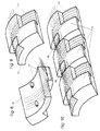
- components 15 are preferably prefabricated reinforced concrete components, which, as will be described below will be assembled into rings with the mounting device and which is the supporting structure of the tunnel tube, i.e. the tunnel expansion 9 form.
- the components 15 can in precast concrete plants manufactured and transported with vehicles.
- the entire reinforcement 17 of the tunnel extension 9 is arranged.
- the reinforcement 17 projects on one long side (in Direction of the axis of the curvature of the component) and a broad side (transverse to the axis of curvature of the component Side) on the adhesive length of the steel out of component 15.
- On the opposite side in the outside is each Component 15 provided a recess.
- the reinforcement 17 extends only to the edge of the component 15, but has from Bottom of the recess a distance.
- the bars of the reinforcement 17 in longitudinal and in Cross direction by length of detention. This is shown in Figure 10.
- Fig. 10 shows that the bars of the reinforcement 17 in each other in the area 18 in Overlap lengthwise. This creates a continuous reinforcement network, by the measures described below with hardening Mass, e.g. is covered with concrete.
- FIG. 11 shows a special component 15, which is the first component 15 is used in the manufacture of a ring from components 15.
- this component 15 according to FIG. 11 is only one on the outside Provided depression and the rods extending in the circumferential direction the reinforcement protrude over the component 15 on both sides.
- the longitudinal reinforcement bars of reinforcement 17 are only on the opposite side of the recess Component 15 according to FIG. 11.
- FIG. 12 The special component shown in FIG. 12 is shown in FIG used the ring.
- this component 15 there are only those in the longitudinal direction, reinforcement bars running in the direction of the tunnel axis the reinforcement 17 - but not the ones running in the circumferential direction Reinforcing bars - on one side over component 15 about.
- This component 15 has three recesses on its outside on and the circumferential bars of the reinforcement 17th stand over the surfaces of the component running parallel to the axis 14 not over. It is also envisaged that the first and the penultimate Component 15 (the components labeled "1" and "15" in FIG.
- the device according to the invention has an outer support plate 3, which is a tubular steel construction, which during the stem Earth pressure picks up and what parts of the mounting device for the Components 15 carries.
- an outer support plate 3 On the front end of the outer support plate 3 a dismantling head 1 can be attached.
- the mining head 1 is in the embodiment executed as an oblique cutting ring, so that this in particular can be used in soft, unsustainable soil.
- the angle of the bevel is chosen so that no material of the floor can break out of the upper area.
- the earth material in mining area 2 with a construction machine can be excavated with the help of conveyor belts and / or vehicles be transported out of the tube. When digging is not about the imaginary extension of the outer surface of the outer Dig out support plate 3 so that behind the outer support plate 3 no voids are created. So it should be the earth material on outer support plate 3 should be as snug as possible from all sides.
- the outer support plate 3 is used of feed devices, for example hydraulic cylinders 4 are continuously advanced. This creates 2 in mining area no area that could break in, since the outer support plate 3 Earth material supports.
- the outer support plate 3 is set up and controlled also via the feed devices 4, in which shown Embodiment three feed devices 4 in the form of hydraulic cylinders are provided. These hydraulic cylinders 4 are arranged evenly over the circumference of the outer support plate 3 and connected to it.
- the hydraulic cylinders 4 are optionally available same pressure and speed or different Pressure and extendable at different speeds.
- the hydraulic cylinders 4 are supported on the front end of a inner support plate 8 via a provided there, to the outside protruding ring flange.
- the front end of the inner support shield 8 is shown in FIG. 15.
- the inner support plate 8 can be a steel pipe.
- the inner support plate 8 carries parts of the mounting device for the Components 15 and it serves as protective formwork during work.
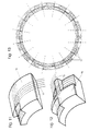
- a rectangular recess 22 is provided behind the flange the components 15 in an installation ring 6 during installation (FIG. 14) are lowerable.
- the advance in turn can also be controlled depending on the concrete pressure. If for example, the specified concrete pressure is no longer maintained can be because of voids in the material or depressions on the Are to be filled on the outside of the components 15, the feed, preferably automatic, slowed down or completely interrupted.
- the concrete 16 is pumped in via a concrete pump via concrete lines 7 and via lines in the rear section of the outer support plate 3 in the space between those assembled for tunnel expansion 9 Components 15 and the outbreak.
- the pressure of the concrete 16 is chosen when pumping in that the Earth pressure, which is initially borne by the outer support plate 3, from Concrete pressure is collected. So is in the area behind that rear end of the outer support plate 3 ensures that in no phase of the excavation is free and can collapse.
- Ingressing groundwater or water from mining area 2 longitudinal water veins is through the cross shield 10 in the area shut off in front of the mounting ring 6 and can be pumped out be pumped into the tunnel tube.
- concrete pipes 23 be provided on the inner surface of the outer support plate 3 flow out. This prevents the concrete pressure behind the outer support plate 3 suddenly drops when the outer support plate 3 in its forward movement recesses on the outside of the Components 15 releases. It is preferred that 15 per component lateral concrete lines 23 are provided.
- Leakage of concrete 16 or cement slurry in the area of the mounting ring 6 can by appropriate sealing measures on the outside Support shield 3 in front of the side concrete lines 23 prevented become.
- the concrete line 7 is in the inner support plate 8 in the direction of Longitudinally movably supported, since the inner support plate 8 independently can be moved from the outer support plate 3.
- the administration 7 is connected to an annular channel in the outer support plate 3, from which several axial lines (channels) leading to the rear Guide end of support plate 3, go out.
- the inner support plate 8 from the area of the Recess 22 through the components 15 placed in the mounting ring 6 have a slightly smaller diameter so that the Movements are easy to perform.
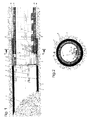
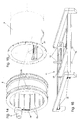
- Fig. 1 shows the outer support plate 3 in the position (retracted Hydraulic cylinder 4) in which the installation of a ring of components 15 is carried out.
- the hydraulic cylinders 4 are in this position retracted so that the inner support plate 8 with its ring flange maximally retracted into the rear end of the outer support plate 3 is.
- the pistons of the hydraulic cylinder 4 are with the flange of the inner support shield 8 connected tensile and pressure resistant.
- Fig. 3 shows the position of the outer support plate on a larger scale 3 and the inner support plate 8 of FIG. 1 again.
- Fig. 3 also shows a built-in table 11 on the inner support plate 8 is constructed, and is located above the mounting ring 6.
- the built-in table 11 is shown again in an oblique view in FIG. 16. With the help of the built-in table 11, components 15 are placed over feed rails 14 can be brought up to the built-in table 11 from Built-in table 11 taken over.
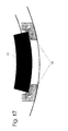
- feed rails 14 An exemplary embodiment for the feed rails 14 is shown in FIG. 17 shown. These feed rails 14 have rollers for supporting the components 15 to be conveyed from below and lateral guide rollers, which attack on the side surfaces of the components 15.
- the built-in table 11 consists of a frame construction with two Rails 20 in which a built-in carriage 21 can be moved on rollers is led.
- the mounting ring 16 consists of a steel tube, which is dimensioned so that it can accommodate a complete ring of components 15.
- An end flange of the mounting ring 6 has a ring gear 24 inside provided with which a pinion of a gear motor 5 meshes, so that the mounting ring 6 can be rotated (in writing).
- the mounting ring 6 is via rollers 28 in grooves in the inside of the outer support plate 3 rotatably mounted. There are two rows of rollers 28 intended.
- On the inner surface of the mounting ring 6 are wedge-shaped Guide rails 25 attached to the lateral sliding of Prevent components 15 and an exact fit in the mounting ring 6th manufactured new ring from components 15 with an already installed Secure ring from components 15.
- V-shaped cutouts are provided through which the ribs 25 pass, if the inner support plate 8 is relative to the mounting ring 6 emotional.
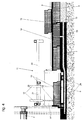
- Fig. 3 When inserting components 15 in the mounting ring 6 is as in following described with reference to FIGS. 3 to 7, proceeded.
- Fig. 3 is shown that the inner support plate 8 in its foremost Position is and the hydraulic cylinders 4 are fully retracted.
- the Components 15 are on the feed rails 14 to under the built-in table 11 moves.
- the installation car 21 of the installation table 11 is moved over a component 15 lying at the end of the feed rails 14.
- the component 15 is received with the lifting claws 13 and raised by actuating the cylinder 12.
- the built-in car 21 together with the component 15 into the mounting ring 6 moved forward and the component 15 then through the rectangular Recess 22 of the inner support plate 8 on the mounting ring 6 lowered (Fig. 4).
- the lifting claws 13 are released from the component 15, raised, and the built-in cart 21 moved back so that it could be received of the next component 15 is ready. Then the mounting ring 6 rotated one position with the help of the geared motor 5, so that it is in the position for receiving the next component 15 correct position.
- FIG. 13 also shows that those labeled "1" and "15" in FIG. 13 Components on their side that correspond to the last component 15 according to FIG. 12 are more inclined than the components according to FIG. 8 and 9 and that the component according to FIG. 12 parallel side surfaces has so that it can be used.
- Fig. 13 shows a cross section of an assembled ring Components 15, the dashed lines the necessary alignment the side faces of the components 15 show.
- the thin lines show the ring reinforcement 17 and its lateral protrusions.
- the Numbers "1" to "16" entered in the components indicate the sequence the installation of components 15.
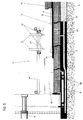
- Fig. 5 shows how by extending the hydraulic cylinder 4 of the Ring of components 15 from the flange at the front end of the inner Support shield 8 from the tunnel construction 9 already made Components 15 is added.
- the longitudinal reinforcements of the components 15 overlap by sticking length, which also means in the longitudinal direction of the tunnel extension 9 a continuous reinforcement is created.
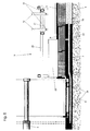
- Fig. 6 shows how from this point in time by further extending the hydraulic cylinder 4 pushed the outer support plate 3 further becomes.
- Fig. 7 shows how by pulling the hydraulic cylinder 4 that inner support plate 8 is tightened, etc. until the recess 22 again at the front end of the inner support plate 8 the mounting ring 6 comes to rest, so that with the manufacture of the next ring of components 15 can be started.
- an embodiment of the invention can be as follows being represented:
- an installation device comes with a Installation ring 6 for use, with which the finished parts 15 mechanically assembled into a ring and attached to the tunnel tube 9.
- a steel tube construction is used as the outer support shield 3 for the propulsion used, which is driven with hydraulic presses 4, while earth material is being excavated inside the pipe.
- the Hydraulic presses 4 are based on the already assembled Tunnel expansion 9 from.
- the finished parts 15 are each on the front End of the tunnel expansion 9 put on.
- the areas of the overlapping Reinforcement, and the cavity behind the outer support shield 3 are pressed out with concrete.
Landscapes
- Engineering & Computer Science (AREA)
- Mining & Mineral Resources (AREA)
- Structural Engineering (AREA)
- Architecture (AREA)
- Life Sciences & Earth Sciences (AREA)
- General Life Sciences & Earth Sciences (AREA)
- Geochemistry & Mineralogy (AREA)
- Geology (AREA)
- Civil Engineering (AREA)
- Environmental & Geological Engineering (AREA)
- Lining And Supports For Tunnels (AREA)
Abstract
Description
Die Erfindung betrifft ein Verfahren und eine Vorrichtung zum Vortreiben und zum Ausbauen von Tunnels und Stollen, insbesondere in nicht tragfähigem Boden mit den Merkmalen der einleitenden Teile des Verfahrenshauptanspruches bzw. des Vorrichtungshauptanspruches.The invention relates to a method and a device for advancing and to expand tunnels and tunnels, especially in unsustainable floor with the characteristics of the introductory parts of the Main procedural claim or main device claim.
Die Erfindung betrifft weiters (Fertig-)Bauteile, die beim Ausführen des erfindungsgemäßen Verfahrens verwendet werden können, und die mit der erfindungsgemäßen Vorrichtung zum Ausbauen des Tunnels verarbeitet werden können.The invention further relates to (prefabricated) components that are used when executing of the method according to the invention can be used, and the with the device according to the invention for expanding the tunnel can be processed.
Beim Vortreiben von Tunnels und Stollen wird, insbesondere wenn dies in nicht tragfähigem Boden erfolgt, ein Vortriebsschild verwendet, in dessen Schutz mit einer Einbauvorrichtung der Ausbau des Tunnels oder Stollens mit Bauteilen, insbesondere mit Fertigbauteilen, erfolgt. Das Vortriebsschild wird mit einer Vorschubvorrichtung, beispielsweise einer Kolben-Zylinder-Anordnung, die sich auf dem bereits hergestellten Tunnelausbau abstützt, vorgetrieben. Während des Vortriebes wird in den Raum zwischen Tunnelausbau und Ausbruch eine härtende Masse, wie beispielsweise Beton, eingepreßt.When driving tunnels and tunnels, especially if this is takes place in unsustainable soil, uses a jacking sign, in its protection the expansion of the tunnel with an installation device or tunnels with components, in particular with prefabricated components, he follows. The tunneling shield is equipped with a feed device, for example a piston-cylinder arrangement, which is located on the supports the tunnel construction that has already been produced, driven forward. While the tunneling is carried out in the space between tunnel expansion and excavation a hardening mass, such as concrete, is pressed in.
Aus der AT 399 203 B (Mayreder) ist eine Vorrichtung zum Vortreiben von Tunnel und Stollen bekannt, bei der im Schutz des Schildschwanzes Tübbingfertigteile angebracht werden. Der Raum zwischen dem Ausbruch und dem Tunnelausbau wird mit einem plastisch verformbaren und nicht zusammendrückbaren Material ausgefüllt. Dies läßt kontrollierte Gebirgsverformungen zu.AT 399 203 B (Mayreder) is a device for advancing known from tunnels and tunnels, in the protection of the shield tail Prefabricated segments are attached. The space between that Eruption and tunnel expansion becomes with a plastically deformable and filled in non-compressible material. This leaves controlled Mountain deformations too.
Bei Einsatz dieser Vorrichtung werden für den Innenausbau Tübbingbausteine verwendet, die mit einer hydraulischen Einbauvorrichtung eingebaut werden, und die einzeln zu koppeln sind. Nachteil dieser Vorgangsweise ist, daß für das Einbauen und Koppeln der Fertigteile mehrere Arbeitsvorgänge erforderlich sind, und daß das Verfahren daher zeitaufwendig, schwer vollautomatisier- und computersteuerbar ist. When using this device, segment building blocks are used for the interior used with a hydraulic mounting device be installed, and which are to be coupled individually. Disadvantage of this The procedure is that for the installation and coupling of the finished parts multiple operations are required and that the procedure therefore time consuming, difficult to fully automate and computer control is.
Aus der EP 132 066 A1 (Mini Tunnels Int. Ltd) ist eine Vorrichtung bekannt, bei der Fertigteile zu einem Ring zusammengesetzt werden, von hinten auf eine Röhre aufgesetzt, und mit Pressen vorgeschoben werden. Gleichzeitig wird der Spalt zwischen Ausbruchsraum und eingebauter Tunnelrohre, über eine Rohrleitung mit erhärtender Masse ausgefüllt. Nachteil dieser Vorgangsweise ist, daß bei größeren Bauabschnitten ein über längere Zeit nicht erstarrendes Hinterfüllmaterial verwendet werden muß, da sonst durch die steigende Mantelreibung ein Vorschieben der Tunnelröhre, und ein Einbringen des Füllmaterials nicht möglich ist. Wird ein Material verwendet, das über längere Zeit plastisch bleibt, besteht die Gefahr des Absinkens und der Verformung der Röhre bei Belastung im Inneren der Röhre. Ein weiteres Problem liegt in der schwierigen Steuerbarkeit des Vortriebes über weitere Strecken.A device is known from EP 132 066 A1 (Mini Tunnels Int. Ltd) known in which finished parts are assembled into a ring, placed on a tube from behind and pushed forward with presses become. At the same time, the gap between the breakout area and built-in tunnel pipes, via a pipe with hardening mass filled out. The disadvantage of this procedure is that with larger ones Construction sections a backfill material that does not solidify over a long period of time must be used, otherwise due to the increasing skin friction advancing the tunnel tube, and inserting the Filling material is not possible. If a material is used that remains plastic for a long time, there is a risk of sinking and the deformation of the tube when loaded inside the tube. On Another problem is the difficult controllability of the jacking over longer distances.
Aus der FR 2 585 067 A (GTM) ist eine Tunnelbauvorrichtung bekannt, bei der der Ausbruchsdurchmesser nur geringfügig größer ist als der Außendurchmesser des fertigen Tunnelausbaues. Auf das Ausfüllen des Zwischenraumes zwischen Ausbruch und Tunnelausbau wird dabei verzichtet. Die Vorrichtung stützt sich beim Vorbau mit Hydraulikpressen auf dem bestehenden Ausbau ab.A tunnel construction device is known from FR 2 585 067 A (GTM), where the excavation diameter is only slightly larger than that Outside diameter of the finished tunnel expansion. On completing the The space between the excavation and tunnel expansion is dispensed with. The device is supported in the stem with hydraulic presses on the existing expansion.
Aufgabe der Erfindung ist es, ein Verfahren und eine Vorrichtung zum Herstellen von Tunnelröhren zu schaffen, wobei das Gefüge des Materials um die Tunnelröhre nicht verändert wird, bei dem durch einfache Abläufe ein vollautomatisches, computergesteuertes Arbeiten möglich ist, und mit der in einem Arbeitsgang eine tragfähige Tunnelröhre hergestellt werden kann.The object of the invention is a method and an apparatus for Manufacture to create tunnel tubes, taking the structure of the material around the tunnel tube is not changed, by simple Processes a fully automatic, computer-controlled work is possible, and with a stable tunnel tube in one work step can be manufactured.
Diese Aufgabe wird, was das Verfahren anlangt, mit den Merkmalen des Verfahrenshauptanspruches gelöst.As far as the procedure is concerned, this task is combined with the characteristics of Main procedural claim solved.
Bevorzugte und vorteilhafte Ausgestaltungen des erfindungsgemäßen Verfahrens sind Gegenstand der vom Verfahrenshauptanspruch abhängigen Unteransprüche.Preferred and advantageous embodiments of the invention Procedures are the subject of dependent on the main procedural claim Subclaims.
Was die erfindungsgemäße Vorrichtung anlangt, wird die genannte Aufgabe mit den Merkmalen des Vorrichtungshauptanspruches gelöst.As far as the device according to the invention is concerned, the said Task solved with the features of the main device claim.
Bevorzugte und vorteilhafte Ausgestaltungen der erfindungsgemäßen Vorrichtung sind Gegenstand der vom Vorrichtungshauptanspruch abhängigen Unteransprüche.Preferred and advantageous embodiments of the invention Devices are the subject of dependent on the main device claim Subclaims.
Zur Lösung der erfindungsgemäßen Aufgabe trägt in vorteilhafter Weise ein Bauteil bei, der bevorzugt so ausgebildet ist, wie dies in dem auf dem Bauteil gerichteten unabhängigen Anspruch gekennzeichnet ist.To achieve the object of the invention contributes advantageously Include a component that is preferably designed as shown in characterized on the component directed independent claim is.
Bevorzugte und vorteilhafte Ausgestaltungen des erfindungsgemäßen Bauteils sind Gegenstand der Unteransprüche.Preferred and advantageous embodiments of the invention Component are the subject of the dependent claims.
Von Vorteil bei dem erfindungsgemäßen Verfahren ist es, daß Tunnel und Stollen schnell und sicher vorgetrieben und ausgebaut werden können.It is advantageous in the method according to the invention that tunnels and tunnels can be driven and removed quickly and safely can.
Ein Vorteil der erfindungsgemäßen Vorrichtung ist es, daß sie einfach aufgebaut ist und ohne Schwierigkeiten vollautomatisch betrieben werden kann.An advantage of the device according to the invention is that it is simple is set up and operated fully automatically without difficulty can be.
Der erfindungsgemäße Bauteil hat den Vorteil, daß es kostengünstig als Fertigbauteil und in Serie, gegebenenfalls auch automatisiert hergestellt werden kann.The component according to the invention has the advantage that it is inexpensive as a prefabricated component and in series, possibly also automated can be manufactured.
In einer bevorzugten Ausführungsform wird bei dem erfindungsgemäßen Verfahren mit einem Vortriebsschild (äußeres Stützschild), das ein im wesentlichen rohrförmiger Bauteil ist, gearbeitet, das an seinem hinteren Ende mit einem inneren Stützschild, das ebenfalls ein rohrförmiger Bauteil ist, überlappt. Das innere Stützschild stützt die Bauteile während sie zu einem Ring zusammengefügt werden bis zum Erhärten der zwischen dem Ausbruch und dem Ring aus Bauteilen eingebrachten, erhärtenden Masse (Beton) ab.In a preferred embodiment, the inventive Procedure with a tunneling shield (outer support shield), the one is essentially tubular component, worked on its rear end with an inner support shield that is also a tubular component is overlapped. The inner support shield supports the components while they are assembled into a ring by Hardening of the components inserted between the excavation and the ring hardening mass (concrete).
Die bei der erfindungsgemäßen Vorrichtung vorgesehene Einbauvorrichtung besteht in einer Ausführungsform aus einem drehbaren Ein> bauring und einem am vorderen Ende des inneren Stützschildes vorgesehenen Einbautisch. Mit diesem Einbautisch werden in einer Ausführungsform die Bauteile, die Stahlbetonfertigbauteile sein können, durch eine Öffnung am vorderen Ende des inneren Stützschildes auf den Einbauring abgesetzt. Dann wird der Einbauring um einen Schritt ) weitergedreht und der nächste Bauteil auf den Einbauring abgesetzt, bis ein Ring aus Bauteilen geschlossen ist. Hiezu ist in einer Ausführungsform der Einbauring mit einem Motor verdrehbar.The installation device provided in the device according to the invention consists in one embodiment of a rotatable Ein> construction ring and one provided at the front end of the inner support shield Built-in table. With this built-in table, in one embodiment the components that can be precast reinforced concrete components through an opening at the front end of the inner support shield the mounting ring. Then the mounting ring is one step ) turned further and the next component placed on the mounting ring, until a ring of components is closed. To do this is in one Embodiment of the mounting ring rotatable with a motor.
Sobald ein Ring aus Bauteilen fertiggestellt ist, wird der so hergestellte Ring bevorzugt durch Ausfahren der am äußeren Stützschild abgestützten und beispielsweise einem Flansch am vorderen Ende des inneren Stützschildes abgestützten Druckmittelzylinderanordnungen aus dem Einbauring herausgeschoben, bis er an den letzten zuvor hergestellten Ring des Tunnelausbaues anliegt. Im Anschluß daran wird das äußere Stützschild (Vortriebsschild) durch fortgesetztes Ausfahren der Kolbenzylinderanordnungen vorgeschoben, wobei der Tunnel oder Stollen durch Abbauen weiter vorgetrieben wird.As soon as a ring of components is finished, the one produced in this way Ring preferred by extending the outer support plate supported and for example a flange at the front end of the inner support shield supported pressure cylinder arrangements pushed out of the mounting ring until it is at the last one manufactured ring of tunnel expansion. After that the outer support shield (tunneling shield) is continued by Extending the piston cylinder assemblies advanced, the Tunnels or tunnels are driven forward by dismantling.
Als nächster Schritt werden die Kolbenzylinderanordnungen wieder eingefahren, so daß das innere Stützschild und der Einbauwagen vorwärtsbewegt werden, bis sie in die Stellung gelangt sind, in der der nächste Ring aus Bauteilen hergestellt werden kann.The next step is the piston-cylinder arrangements again retracted so that the inner support plate and the built-in car be moved forward until they have reached the position in which the next ring can be made from components.
In einer bevorzugten Ausführungsform besitzt die erfindungsgemäße Vorrichtung als wesentliche Bauteile ein äußeres Stützschild, dessen vorderes Ende beispielsweise als schräger Schneidring ausgebildet ist, wobei am vorderen Ende des äußeren Stützschildes an sich bekannte Vorrichtungen zum Abtragen von Material vorgesehen sein können. Weiterer Bestandteil der erfindungsgemäßen Vorrichtung in einer bevorzugten Ausführungsform ist der innere Stützschild, der in jeder Relativlage zwischen äußerem Stützschild und innerem Stützschild diesen überlappt und der als vorübergehende Abstützung für den aus Bauteilen hergestellten Tunnelausbau dient. In dem inneren Stützschild ist ein Einbautisch angeordnet, mit dem beispielsweise über Zuführschienen zugeführte Bauteile auf den Einbauring, der im hinteren Ende des äußeren Stützschildes drehbar gelagert ist, absetzbar sind.In a preferred embodiment, the invention has Device as essential components an outer support plate, the front end formed for example as an oblique cutting ring is known at the front end of the outer support plate Devices for removing material may be provided can. Another component of the device according to the invention in a preferred embodiment is the inner support shield, which in any relative position between the outer support plate and the inner support plate this overlaps and serves as a temporary support for serves the tunnel construction made of components. In the inside Support plate is a built-in table with which, for example Components fed via feed rails onto the mounting ring, which in the rear end of the outer support plate is rotatably supported, removable are.
Für die Relativbewegungen zwischen äußerem Stützschild und innerem Stützschild sind Linearmotore, insbesondere Kolben-Zylinder-Anordnungen, die z.B. hydraulisch betätigt werden können, vorgesehen, die sich beispielsweise über einen Flansch am vorderen Ende des inneren Stützschildes am bereits hergestellten Tunnelausbau aus Bauteilen abstützen. For the relative movements between the outer support shield and the inner one Support shield are linear motors, especially piston-cylinder arrangements, e.g. can be operated hydraulically, provided which, for example, has a flange at the front end of the inner support shield on the tunnel construction already made Support components.
Die im Rahmen der Erfindung verwendbaren Bauteile sind insbesondere Fertigbauteile aus Stahlbeton, die eine im wesentlichen kreisringsektorförmige Querschnittsform besitzen. An ihrer Außenseite weisen diese Bauteile einander bevorzugt diagonal gegenüberliegende, zum Rand hin offene Aussparungen (Vertiefungen) auf, in denen die Bewehrung freiliegt, wobei die Bewehrung sowohl in Umfangsrichtung (quer zur Achse der Krümmung der Bauteile), als auch in Achsrichtung (in Richtung der Achse der Krümmung der Bauteile) ausgerichtete Bewehrungsstäbe vorgesehen sind. Sowohl die in Umfangsrichtung verlaufenden Bewehrungsstäbe, als auch die in Achsrichtung verlaufenden Bewehrungsstäbe stehen über die Bauteile in neben den Aussparungen liegenden Bereichen über. Dieser Überstand ist wenigstens so groß bemessen, wie die Haftlänge dieser Bewehrungsstäbe in Beton. Zusätzlich zu den Standardbauteilen ist ein erster Sonderbauteil, der als erster Bauteil in den Einbauring eingesetzt wird, und ein zweiter Sonderbauteil vorgesehen, der als letzter Bauteil in den sonst fertiggestellten Ring aus Bauteilen eingesetzt wird. Letzterer besitzt zueinander parallel verlaufende, in Richtung der Krümmungsachse ausgerichtete Seitenwände.The components that can be used in the context of the invention are in particular Prefabricated components made of reinforced concrete, which is an essentially circular sector Have cross-sectional shape. Point on the outside these components are preferably diagonally opposite to each other Open recesses (recesses) on the edge, in which the reinforcement exposed, the reinforcement both in the circumferential direction (transversely to the axis of the curvature of the components), as well as in the axial direction (in Reinforcement bars aligned in the direction of the axis of the curvature of the components) are provided. Both those running in the circumferential direction Reinforcement bars, as well as those running in the axial direction Reinforcing bars are above the components in next to the recesses lying areas above. This excess is at least as large dimensioned as the length of adhesion of these reinforcing bars in concrete. In addition to the standard components is a first special component, which as first component is inserted in the mounting ring, and a second Special component provided, which is the last component in the otherwise completed ring of components is used. The latter has mutually parallel, in the direction of the axis of curvature aligned side walls.
Weitere Einzelheiten und Merkmale und Vorteile der Erfindung ergeben sich aus der nachstehenden Beschreibung eines bevorzugten Ausführungsbeispieles einer für das Durchführen des Verfahrens geeigneten Vorrichtung und der beispielhaft dargestellten Bauteile.Further details and features and advantages of the invention emerge from the following description of a preferred embodiment one suitable for performing the method Device and the components shown as an example.
Es zeigt:
Zunächst werden anhand der Fig. 8 bis 12 die erfindungsgemäßen
Bauteile 15 beschrieben. Diese Bauteile 15 sind bevorzugt Stahlbetonfertigbauteile,
die, wie weiter unten noch beschrieben werden
wird, mit der Einbauvorrichtung zu Ringen zusammenfügbar sind und
welche die tragende Konstruktion der Tunnelröhre, also den Tunnelausbau
9 bilden. Die Bauteile 15 können in Betonfertigteilwerken
hergestellt und mit Fahrzeugen zutransportiert werden. In den Bauteilen
15 ist die gesamte Bewehrung 17 des Tunnelausbaues 9 angeordnet.
Die Bewehrung 17 ragt jeweils auf einer Längsseite (in
Richtung der Achse der Krümmung des Bauteils verlaufende Seite) und
einer Breitseite (quer zur Achse der Krümmung des Bauteiles verlaufende
Seite) auf Haftlänge des Stahls aus dem Bauteil 15 heraus.
Auf der jeweils gegenüberliegenden Seite ist in der Außenseite jedes
Bauteils 15 eine Vertiefung vorgesehen. Im Bereich dieser Vertiefung
ragt die Bewehrung 17 nur bis zum Rand des Bauteils 15, hat aber vom
Boden der Vertiefung einen Abstand. Beim Zusammenfügen der Bauteile
15 überlappen sich die Stäbe der Bewehrung 17 in Längs- und in
Querrichtung um Haftlänge. Dies ist in Fig. 10 gezeigt. Fig. 10
zeigt, daß die Stäbe der Bewehrung 17 einander im Bereich 18 in
Längsrichtung überlappen. So entsteht ein durchgehendes Bewehrungsnetz,
das durch die weiter unten beschriebenen Maßnahmen mit erhärtender
Masse, z.B. mit Beton ummantelt wird.First, the invention according to FIGS. 8 to 12
Fig. 11 zeigt einen Sonder-Bauteil 15, der als erster Bauteil 15
beim Herstellen eines Ringes aus Bauteilen 15 verwendet wird. Bei
diesem Bauteil 15 gemäß Fig. 11 ist an der Außenseite lediglich eine
Vertiefung vorgesehen und die in Umfangsrichtung verlaufenden Stäbe
der Bewehrung stehen an beiden Seiten über den Bauteil 15 über. Die
in Längsrichtung verlaufenden Bewehrungsstäbe der Bewehrung 17
stehen nur auf der der Aussparung gegenüberliegenden Seite des
Bauteils 15 gemäß Fig. 11 über.11 shows a
Als letzter Bauteil 15 wird die in Fig. 12 gezeigte Sonderform in
den Ring eingesetzt. Bei diesem Bauteil 15 stehen nur die in Längsrichtung,
also in Richtung der Tunnelachse verlaufenden Bewehrungsstäbe
der Bewehrung 17 - nicht aber die in Umfangsrichtung verlaufenden
Bewehrungsstäbe - auf einer Seite über den Bauteil 15
über. Dieser Bauteil 15 weist an seiner Außenseite drei Vertiefungen
auf und die in Umfangsrichtung verlaufenden Stäbe der Bewehrung 17
stehen über die parallel zur Achse verlaufenden Flächen des Bauteils
14 nicht über. Zudem ist vorgesehen, daß der erste und der vorletzte
Bauteil 15 (die in Fig. 13 mit "1" und "15" bezeichneten Bauteile)
über eine schräger als eine Radialebene gestellte, in Achsrichtung
verlaufende Seitenfläche und der letzte Bauteil 15 über zueinander
parallele Seitenflächen (zur Achse parallel verlaufende Seitenflächen)
verfügen, damit der Ring aus Bauteilen 15 vom Inneren des
Ringes her zusammengesetzt werden kann.The special component shown in FIG. 12 is shown in FIG
used the ring. In this
Nachfolgend werden die einzelnen Bestandteile der erfindungsgemäßen Vorrichtung beschrieben.Below are the individual components of the invention Device described.
Die erfindungsgemäße Vorrichtung besitzt ein äußeres Stützschild 3,
das eine Stahlrohrkonstruktion ist, die während des Vorbaues den
Erddruck aufnimmt und welche Teile der Einbauvorrichtung für die
Bauteile 15 trägt. Auf das vordere Ende des äußeren Stützschildes 3
ist ein Abbaukopf 1 aufsetzbar. Der Abbaukopf 1 ist im Ausführungsbeispiel
als schräger Schneidering ausgeführt, so daß dieser insbesondere
in weichem, nicht tragfähigem Boden einsetzbar ist. Der
Winkel der Abschrägung ist so gewählt, daß kein Material des Bodens
aus dem oberen Bereich ausbrechen kann.The device according to the invention has an
Anstelle des Schneidringes sind auch andere Vorrichtungen einsetzbar.
Das Erdmaterial, das im Abbaubereich 2 mit einer Baumaschine
ausgegraben wird, kann mit Hilfe von Förderbändern und/oder Fahrzeugen
aus der Röhre transportiert werden. Bei den Grabarbeiten ist
nicht über die gedachte Verlängerung der Außenfläche des äußeren
Stützschildes 3 hinaus zu graben, damit hinter dem äußeren Stützschild
3 keine Hohlräume entstehen. Es soll also das Erdmaterial am
äußeren Stützschild 3 von allen Seiten her möglichst satt anliegen.Instead of the cutting ring, other devices can also be used.
The earth material in mining area 2 with a construction machine
can be excavated with the help of conveyor belts and / or vehicles
be transported out of the tube. When digging is
not about the imaginary extension of the outer surface of the outer
Dig out
Während der Abbauarbeiten wird das äußere Stützschild 3 mit Hilfe
von Vorschubvorrichtungen, die beispielsweise Hydraulikzylinder 4
sind, kontinuierlich vorgetrieben. Damit entsteht im Abbaubereich 2
kein Bereich der einbrechen könnte, da das äußere Stützschild 3 das
Erdmaterial stützt.During the dismantling work, the
Das Einrichten und Steuern des äußeren Stützschildes 3 erfolgt
ebenfalls über die Vorschubvorrichtungen 4, wobei im gezeigten
Ausführungsbeispiel drei Vorschubvorrichtungen 4 in Form von Hydraulikzylindern
vorgesehen sind. Diese Hydraulikzylinder 4 sind
gleichmäßig über den Umfang des äußeren Stützschildes 3 angeordnet
und mit diesem verbunden. Die Hydraulikzylinder 4 sind wahlweise mit
gleichem Druck und gleicher Geschwindigkeit oder mit unterschiedlichem
Druck und mit unterschiedlicher Geschwindigkeit ausfahrbar.The
Für jede Richtungsänderung des Vortriebes sind die entsprechenden
Änderungen der Abmessungen der Bauteile 15 im voraus zu berechnen.For every change of direction of the jacking there are the corresponding ones
Calculate changes in the dimensions of the
Die Hydraulikzylinder 4 stützen sich auf dem vorderen Ende eines
inneren Stützschildes 8 über einen dort vorgesehenen, nach außen
abstehenden Ringflansch ab. Das vordere Ende des inneren Stützschildes
8 ist in Fig. 15 dargestellt. Das innere Stützschild 8 kann
ein Stahlrohr sein.The
Das innere Stützschild 8 trägt Teile der Einbauvorrichtung für die
Bauteile 15 und es dient als Schutzschalung während der Arbeiten.The
Am vorderen Ende des Stützschildes 8 ist im unteren Bereich und
hinter dem Flansch eine rechteckige Ausnehmung 22 vorgesehen, über
die beim Einbau die Bauteile 15 in einen Einbauring 6 (Fig. 14)
absenkbar sind.At the front end of the
Damit die Bauteile 15 untereinander fest verbunden werden, und
während des Vortriebes kein leerer Raum hinter dem äußeren Stützschild
3 entsteht, wird in Abstimmung mit dem Vortrieb des äußeren
Stützschildes 3 laufend Beton eingepreßt. Der Vortrieb seinerseits
kann auch in Abghängigkeit vom Betondruck gesteuert werden. Wenn
beispielsweise der festgelegte Betondruck nicht mehr aufrechtgehalten
werden kann, da Hohlräume im Material oder Vertiefungen an der
Außenseite der Bauteile 15 aufzufüllen sind, wird der Vorschub,
vorzugsweise automatisch, verlangsamt, oder zur Gänze unterbrochen.So that the
Der Beton 16 wird mit einer Betonpumpe über Betonleitungen 7 eingepumpt
und über Leitungen im hinteren Abschnitt des äußeren Stützschildes
3 in den Raum zwischen den zum Tunnelausbau 9 zusammengefügten
Bauteilen 15 und dem Ausbruch geleitet.The concrete 16 is pumped in via a concrete pump via
Der Druck des Betons 16 wird beim Einpumpen so gewählt, daß der
Erddruck, der zunächst vom äußeren Stützschild 3 getragen wird, vom
Betondruck aufgefangen wird. So ist auch im Bereich hinter dem
hinteren Ende des äußeren Stützschildes 3 gewährleistet, daß in
keiner Phase des Vortriebes Erde freisteht und einbrechen kann.The pressure of the concrete 16 is chosen when pumping in that the
Earth pressure, which is initially borne by the
Über den Abbaubereich 2 eindringendes Grundwasser oder Wasser aus
längslaufenden Wasseradern wird durch das Querschild 10 im Bereich
vor dem Einbauring 6 abgesperrt und kann mit Hilfe von Pumpen aus
dem Tunnelrohr gepumpt werden.Ingressing groundwater or water from mining area 2
longitudinal water veins is through the cross shield 10 in the area
shut off in front of the mounting
Um das Auffüllen der Aussparungen an der Außenseite der Bauteile 15
sicherzustellen, können im äußeren Stützschild 3 Betonleitungen 23
vorgesehen sein, die an der Innenfläche des äußeren Stützschildes 3
ausmünden. Damit wird verhindert, daß der Betondruck hinter dem
äußeren Stützschild 3 plötzlich abfällt, wenn das äußere Stützschild
3 bei seiner Vorwärtsbewegung Aussparungen an der Außenseite der
Bauteile 15 freigibt. Bevorzugt ist dabei, daß pro Bauteil 15 zwei
seitliche Betonleitungen 23 vorgesehen sind.To fill the recesses on the outside of the
Das Austreten von Beton 16 oder einer Zementschlämme in den Bereich
des Einbauringes 6 kann durch geeignete Dichtungsmaßnahmen am äußeren
Stützschild 3 vor den seitlichen Betonleitungen 23 unterbunden
werden.Leakage of concrete 16 or cement slurry in the area
of the mounting
Die Betonleitung 7 ist im inneren Stützschild 8 in Richtung der
Längsachse beweglich gehaltert, da das innere Stützschild 8 unabhängig
vom äußeren Stützschild 3 bewegt werden kann. Die Leitung
7 ist mit einem ringförmigen Kanal im äußeren Stützschild 3 verbunden,
von dem mehrere achsiale Leitungen (Kanäle), die zum hinteren
Ende des Stützschildes 3 führen, ausgehen. The
Bevorzugt ist es, wenn das innere Stützschild 8 ab dem Bereich der
Ausnehmung 22 durch die Bauteile 15 in den Einbauring 6 gelegt
werden, einen geringfügig kleineren Durchmesser aufweist, damit die
Bewegungen leicht durchführbar sind.It is preferred if the
Fig. 1 zeigt das äußere Stützschild 3 in der Stellung (eingefahrene
Hydraulikzylinder 4) in der der Einbau eines Ringes aus Bauteilen 15
durchgeführt wird. In dieser Stellung sind die Hydraulikzylinder 4
eingefahren, so daß das innere Stützschild 8 mit seinem Ringflansch
maximal in das hintere Ende des äußeren Stützschildes 3 eingefahren
ist. Die Kolben der Hydraulikzylinder 4 sind mit dem Flansch des
inneren Stützschildes 8 zug- und druckfest verbunden.Fig. 1 shows the
Fig. 3 zeigt in größerem Maßstab die Stellung des äußeren Stützschildes
3 und des inneren Stützschildes 8 von Fig. 1 noch einmal.
Fig. 3 zeigt auch einen Einbautisch 11, der auf dem inneren Stützschild
8 aufgebaut ist, und sich über dem Einbauring 6 befindet.Fig. 3 shows the position of the outer support plate on a
Der Einbautisch 11 ist in Fig. 16 noch einmal im Schrägriß gezeigt.
Mit Hilfe des Einbautisches 11 werden Bauteile 15, die über Zuführschienen
14 bis zum Einbautisch 11 herangefördert werden können, vom
Einbautisch 11 übernommen.The built-in table 11 is shown again in an oblique view in FIG. 16.
With the help of the built-in table 11,
Ein Ausführungsbeispiel für die Zuführschienen 14 ist in Fig. 17
gezeigt. Diese Zuführschienen 14 besitzen Rollen zum Abstützen der
heranzufördernden Bauteile 15 von unten her und seitliche Führungsrollen,
die an den Seitenflächen der Bauteile 15 angreifen.An exemplary embodiment for the feed rails 14 is shown in FIG. 17
shown. These feed rails 14 have rollers for supporting the
Der Einbautisch 11 besteht aus einer Rahmenkonstruktion mit zwei
Schienen 20, in denen ein Einbauwagen 21 auf Rollen verfahrbar
geführt ist. Auf dem Einbauwagen 21 sind zwei Hydraulikzylinder 12
aufgebaut, die Hebekrallen 13 aufweisen, die an Ringen in der konkaven
Innenseite der Bauteile 15 angreifen können, um Bauteile 15
anzuheben und abzusenken.The built-in table 11 consists of a frame construction with two
Der Einbauring 6, der in Fig. 14 im Schrägriß gezeigt ist, dient zur
Aufnahme der Bauteile 15 in ihrer richtigen Position und dem Einbau
derselben.The mounting
Der Einbauring 16 besteht aus einem Stahlrohr, das so bemessen ist,
daß es einen vollständigen Ring aus Bauteilen 15 aufnehmen kann. An
einem Endflansch des Einbauringes 6 ist innen ein Zahnkranz 24
vorgesehen, mit dem ein Ritzel eines Getriebemotors 5 kämmt, so daß
der Einbauring 6 (schriftweise) gedreht werden kann. Der Einbauring
6 ist über Rollen 28 in Nuten in der Innenseite des äußeren Stützschildes
3 verdrehbar gelagert. Dabei sind zwei Reihen von Rollen 28
vorgesehen. An der Innenfläche des Einbauringes 6 sind keilförmige
Führungsleisten 25 angebracht, die das seitliche Verrutschen von
Bauteilen 15 verhindern und eine genaue Passung des im Einbauring 6
hergestellten neuen Ringes aus Bauteilen 15 mit einem bereits eingebauten
Ring aus Bauteilen 15 sicherstellen. Um bei einer Relativbewegung
zwischen Einbauring 6 und innerem Stützschild 8 zu erlauben,
sind an der Außenseite des Endflansches des inneren Stützschildes 8
V-förmige Ausschnitte vorgesehen, durch welche die Rippen 25 treten,
wenn sich das innere Stützschild 8 relativ zu dem Einbauring 6
bewegt.The mounting
Beim Einsetzen von Bauteilen 15 in den Einbauring 6 wird wie im
folgenden anhand der Fig. 3 bis 7 beschrieben, vorgegangen. In Fig.
3 ist gezeigt, daß das innere Stützschild 8 in seiner vordersten
Position ist und die Hydraulikzylinder 4 ganz eingefahren sind. Die
Bauteile 15 werden auf den Zuführschienen 14 bis unter den Einbautisch
11 bewegt. Der Einbauwagen 21 des Einbautisches 11 wird
über einen am Ende der Zuführschienen 14 liegenden Bauteil 15 bewegt.
Der Bauteil 15 wird mit den Hebekrallen 13 aufgenommen und
durch Betätigen der Zylinder 12 angehoben. Hierauf wird der Einbauwagen
21 zusammen mit dem Bauteil 15 bis in den Einbauring 6
vorbewegt und der Bauteil 15 anschließend durch die rechteckige
Ausnehmung 22 des inneren Stützschildes 8 auf den Einbauring 6
abgesenkt (Fig. 4). Die Hebekrallen 13 werden vom Bauteil 15 gelöst,
angehoben, und der Einbauwagen 21 zurückbewegt, so daß er zur Aufnahme
des nächsten Bauteils 15 bereit ist. Hierauf wird der Einbauring
6 mit Hilfe des Getriebemotors 5 um eine Position weitergedreht,
so daß er in der für die Aufnahme des nächsten Bauteils 15
richtigen Stellung ist.When inserting
Dieser Ablauf wird so lange wiederholt, bis der Einbauring 6 innen
mit einem Ring aus Bauteilen 15 ausgefüllt ist.This process is repeated until the mounting
Dabei ist darauf zu achten, daß als erster Bauteil ein Bauteil gemäß
Fig. 11, in weiterer Folge Teile gemäß Fig. 8 und 9 und als letzter
Bauteil ein Bauteil gemäß Fig. 12 verwendet wird, so daß ein Ring
aus Bauteilen 15 hergestellt ist, wie dies in Fig. 13 gezeigt ist.
Fig. 13 zeigt auch, daß die in Fig. 13 mit "1" und "15" bezeichneten
Bauteile an ihrer Seite, die dem letzten Bauteil 15 gemäß Fig. 12
benachbart sind, mehr abgeschrägt ist als die Bauteile gemäß Fig. 8
und 9 und daß der Bauteil gemäß Fig. 12 zueinander parallele Seitenflächen
aufweist, damit er eingesetzt werden kann.It is important to ensure that the first component is a component according to
11, parts of FIGS. 8 and 9 and as the last
Component a component according to FIG. 12 is used, so that a ring
is made of
Fig. 13 zeigt einen Querschnitt eines zusammengesetzten Ringes aus
Bauteilen 15, wobei die strichlierten Linien die notwendige Ausrichtung
der Seitenflächen der Bauteile 15 zeigen. Die dünnen Linien
zeigen die Ringbewehrung 17 und ihre seitlichen Überstände an. Die
in die Bauteile eingetragenen Nummern "1" bis "16" geben die Reihenfolge
des Einbaues der Bauteile 15 an.Fig. 13 shows a cross section of an assembled
Es ist darauf hinzuweisen, daß bei Verwendung der Bauteile 15 gemäß
Fig. 8 bis 12 nach dem Absenken eines Bauteils 15 in den Einbauring
6 der Einbauring 6 geringfügig zurückzudrehen ist, damit die Seitenflächen
der Bauteile 15 satt aneinanderliegen.It should be noted that when using the
Fig. 5 zeigt, wie durch das Ausfahren der Hydraulikzylinder 4 der
Ring aus Bauteilen 15 vom Flansch am vorderen Ende des inneren
Stützschildes 8 an den bereits hergestellten Tunnelausbau 9 aus
Bauteilen 15 angefügt wird. Die Längsbewehrungen der Bauteile 15
überlappen sich dabei um Haftlänge, wodurch auch in Längsrichtung
des Tunnelausbaues 9 eine durchgehende Bewehrung entsteht.Fig. 5 shows how by extending the
Fig. 6 zeigt, wie ab diesem Zeitpunkt durch das weitere Ausfahren
der Hydraulikzylinder 4 das äußere Stützschild 3 weiter vorgeschoben
wird.Fig. 6 shows how from this point in time by further extending
the
Fig. 7 zeigt, wie durch das Einziehen der Hydraulikzylinder 4 das
innere Stützschild 8 nachgezogen wird, u.zw. so weit, bis die Ausnehmung
22 am vorderen Ende des inneren Stützschildes 8 wieder über
dem Einbauring 6 zu liegen kommt, so daß mit dem Herstellen des
nächsten Ringes aus Bauteilen 15 begonnen werden kann.Fig. 7 shows how by pulling the
Zusammenfassend kann ein Ausführungsbeispiel der Erfindung wie folgt dargestellt werden: In summary, an embodiment of the invention can be as follows being represented:
Zum Herstellen von Tunnelröhren aus Fertigteilen 15, welche die
gesamte Bewehrung der Tunnelröhre in sich tragen, werden Fertigteile
15 verwendet, die so ausgebildet sind, daß sich die Bewehrungen beim
Zusammensetzen der Teile 15 sowohl in Längs-, als auch in Querrichtung
um die Haftlänge des Bewehrungsstahles überlappen.For the production of tunnel tubes from
Beim Einbau der Fertigteile kommt eine Einbauvorrichtung mit einem
Einbauring 6 zum Einsatz, mit der die Fertigteile 15 maschinell zu
einem Ring zusammengesetzt und an die Tunnelröhre 9 angefügt werden.When installing the finished parts, an installation device comes with a
Für den Vortrieb wird als äußeres Stützschild 3 eine Stahlrohrkonstruktion
verwendet, die mit Hydraulikpressen 4 vorgetrieben wird,
während Erdmaterial im Inneren des Rohres ausgegraben wird. Die
Hydraulikpressen 4 stützen sich dabei auf den schon zusammengesetzten
Tunnelausbau 9 ab. Die Fertigteile 15 werden jeweils am vorderen
Ende des Tunnelausbaues 9 aufgesetzt. Die Bereiche der sich überlappenden
Bewehrung, und der Hohlraum hinter dem äußeren Stützschild 3
werden mit Beton ausgepreßt.A steel tube construction is used as the
Claims (29)
Applications Claiming Priority (2)
| Application Number | Priority Date | Filing Date | Title |
|---|---|---|---|
| AT121199 | 1999-07-13 | ||
| AT121199 | 1999-07-13 |
Publications (1)
| Publication Number | Publication Date |
|---|---|
| EP1069280A1 true EP1069280A1 (en) | 2001-01-17 |
Family
ID=3509030
Family Applications (1)
| Application Number | Title | Priority Date | Filing Date |
|---|---|---|---|
| EP00890216A Withdrawn EP1069280A1 (en) | 1999-07-13 | 2000-07-12 | Method and device for driving a tunnel or gallery and element for their use |
Country Status (1)
| Country | Link |
|---|---|
| EP (1) | EP1069280A1 (en) |
Citations (7)
| Publication number | Priority date | Publication date | Assignee | Title |
|---|---|---|---|---|
| US4091630A (en) * | 1977-05-03 | 1978-05-30 | Kubota, Ltd. | Intermediate sleeve for installing pipeline by propelling pipes underground |
| EP0132066A1 (en) | 1983-06-27 | 1985-01-23 | Rees Construction Services Limited | Tunnelling and tunnel relining equipment |
| DE3515680A1 (en) * | 1983-09-07 | 1986-11-06 | Dyckerhoff & Widmann AG, 8000 München | Method for manufacturing a tubular underground cavity, e.g. a pipeline, as well as device for implementing the method |
| FR2585067A1 (en) | 1985-07-19 | 1987-01-23 | Gtm Ets Sa | LARGE DEPTH OF UNDERGROUND GALLERY SHIELD |
| AT399203B (en) | 1992-05-29 | 1995-04-25 | Mayreder Kraus & Co Ing | Apparatus for driving tunnels and galleries |
| US5846027A (en) * | 1996-02-22 | 1998-12-08 | Toyo Technos Co., Ltd. | Semi-shield method and apparatus for the same |
| EP0897050A1 (en) * | 1997-08-14 | 1999-02-17 | I.T.M. Industriele Tunnelbouw Methode C.V. | Method of building a lined tunnel |
-
2000
- 2000-07-12 EP EP00890216A patent/EP1069280A1/en not_active Withdrawn
Patent Citations (8)
| Publication number | Priority date | Publication date | Assignee | Title |
|---|---|---|---|---|
| US4091630A (en) * | 1977-05-03 | 1978-05-30 | Kubota, Ltd. | Intermediate sleeve for installing pipeline by propelling pipes underground |
| EP0132066A1 (en) | 1983-06-27 | 1985-01-23 | Rees Construction Services Limited | Tunnelling and tunnel relining equipment |
| US4594025A (en) * | 1983-06-27 | 1986-06-10 | Rees Construction Services Limited | Tunnelling and tunnel relining equipment |
| DE3515680A1 (en) * | 1983-09-07 | 1986-11-06 | Dyckerhoff & Widmann AG, 8000 München | Method for manufacturing a tubular underground cavity, e.g. a pipeline, as well as device for implementing the method |
| FR2585067A1 (en) | 1985-07-19 | 1987-01-23 | Gtm Ets Sa | LARGE DEPTH OF UNDERGROUND GALLERY SHIELD |
| AT399203B (en) | 1992-05-29 | 1995-04-25 | Mayreder Kraus & Co Ing | Apparatus for driving tunnels and galleries |
| US5846027A (en) * | 1996-02-22 | 1998-12-08 | Toyo Technos Co., Ltd. | Semi-shield method and apparatus for the same |
| EP0897050A1 (en) * | 1997-08-14 | 1999-02-17 | I.T.M. Industriele Tunnelbouw Methode C.V. | Method of building a lined tunnel |
Similar Documents
| Publication | Publication Date | Title |
|---|---|---|
| DE3043312A1 (en) | METHOD AND DEVICE FOR DRIVING A SLIDE SHUTTER | |
| DE2550050C2 (en) | Device for driving tunnels or the like. by means of a shoring sign with the introduction of an in-situ concrete lining | |
| DE69310411T2 (en) | Device for digging tunnels | |
| DE2108591C3 (en) | Device and method for implementing the shield construction method for the construction of tunnels and galleries | |
| DE2921907C2 (en) | ||
| DE2739079A1 (en) | Multiple tunnel construction system - uses intermediate wall of pilot tunnel to support and guide measuring ring for adjacent tunnel | |
| DE3521888C2 (en) | ||
| DE2706244C2 (en) | Knife driving method and knife for driving tunnels, galleries and the like with simultaneous introduction of a concrete lining | |
| DE3218643A1 (en) | Method of producing an underground tunnel structure | |
| DE2505980A1 (en) | Tunnel tube section forwarding - uses hydraulic or pneumatic pressure from pressure pipe between component and abutment | |
| AT396505B (en) | METHOD AND DEVICE FOR THE UNDERGROUND PRODUCTION OF CHANNELS, TUBES OR THE LIKE. | |
| DE2450281A1 (en) | Machine for excavation and shoring of trenches - has hydraulically actuated excavation plates with space for prefabricated shoring plates | |
| DE3520092C2 (en) | ||
| DE2109384C3 (en) | Method and apparatus for producing tubular tunnels, galleries or the like. in shield driving with a lining made of in-situ concrete | |
| DE3244040C2 (en) | ||
| DE2622202C2 (en) | Method and device for driving a deep trench using the knife shield method, in particular for the construction of tunnels | |
| DE2558670A1 (en) | JACKING KNIFE FOR A SHORING SIGN AND METHOD FOR PLACING IN-SITE CONCRETE CONSTRUCTION WHEN DRIVING TUNNELS, DRIVES, OR THE DGL. BY MEANS OF A SHIELD SIGN | |
| CH708408B1 (en) | Method and apparatus for building a tunnel. | |
| DE2109383C2 (en) | Method for underground driving and immediate lining of tunnels, tunnels or the like | |
| DE1187658B (en) | Method for the underground construction of tunnels, galleries or similar elongated structures using a driving shield | |
| DE2605741A1 (en) | Mine heading or tunnelling shield - has trailing knives sliding forward on wall supports and telescopically linked to forward cutters | |
| DE838276C (en) | Telescoping method for propelling a hollow body in any direction | |
| DE2531007C3 (en) | Method and device for creating working shafts within trenches driven by shield driving | |
| DE3609791C2 (en) | ||
| DE1290943B (en) | Method and shield for producing a pipe-like structure running in the ground |
Legal Events
| Date | Code | Title | Description |
|---|---|---|---|
| PUAI | Public reference made under article 153(3) epc to a published international application that has entered the european phase |
Free format text: ORIGINAL CODE: 0009012 |
|
| AK | Designated contracting states |
Kind code of ref document: A1 Designated state(s): AT BE CH CY DE DK ES FI FR GB GR IE IT LI LU MC NL PT SE |
|
| AX | Request for extension of the european patent |
Free format text: AL;LT;LV;MK;RO;SI |
|
| AKX | Designation fees paid | ||
| REG | Reference to a national code |
Ref country code: DE Ref legal event code: 8566 |
|
| STAA | Information on the status of an ep patent application or granted ep patent |
Free format text: STATUS: THE APPLICATION IS DEEMED TO BE WITHDRAWN |
|
| 18D | Application deemed to be withdrawn |
Effective date: 20010718 |