EP1069059A2 - Dispositif de transport de feuilles - Google Patents
Dispositif de transport de feuilles Download PDFInfo
- Publication number
- EP1069059A2 EP1069059A2 EP00114166A EP00114166A EP1069059A2 EP 1069059 A2 EP1069059 A2 EP 1069059A2 EP 00114166 A EP00114166 A EP 00114166A EP 00114166 A EP00114166 A EP 00114166A EP 1069059 A2 EP1069059 A2 EP 1069059A2
- Authority
- EP
- European Patent Office
- Prior art keywords
- sheet
- carrying
- detecting unit
- data
- paper
- Prior art date
- Legal status (The legal status is an assumption and is not a legal conclusion. Google has not performed a legal analysis and makes no representation as to the accuracy of the status listed.)
- Withdrawn
Links
Images


Classifications
-
- B—PERFORMING OPERATIONS; TRANSPORTING
- B65—CONVEYING; PACKING; STORING; HANDLING THIN OR FILAMENTARY MATERIAL
- B65H—HANDLING THIN OR FILAMENTARY MATERIAL, e.g. SHEETS, WEBS, CABLES
- B65H5/00—Feeding articles separated from piles; Feeding articles to machines
- B65H5/22—Feeding articles separated from piles; Feeding articles to machines by air-blast or suction device
- B65H5/222—Feeding articles separated from piles; Feeding articles to machines by air-blast or suction device by suction devices
- B65H5/224—Feeding articles separated from piles; Feeding articles to machines by air-blast or suction device by suction devices by suction belts
-
- B—PERFORMING OPERATIONS; TRANSPORTING
- B65—CONVEYING; PACKING; STORING; HANDLING THIN OR FILAMENTARY MATERIAL
- B65H—HANDLING THIN OR FILAMENTARY MATERIAL, e.g. SHEETS, WEBS, CABLES
- B65H2404/00—Parts for transporting or guiding the handled material
- B65H2404/20—Belts
- B65H2404/26—Particular arrangement of belt, or belts
- B65H2404/264—Arrangement of side-by-side belts
-
- B—PERFORMING OPERATIONS; TRANSPORTING
- B65—CONVEYING; PACKING; STORING; HANDLING THIN OR FILAMENTARY MATERIAL
- B65H—HANDLING THIN OR FILAMENTARY MATERIAL, e.g. SHEETS, WEBS, CABLES
- B65H2406/00—Means using fluid
- B65H2406/30—Suction means
- B65H2406/36—Means for producing, distributing or controlling suction
- B65H2406/366—Means for producing, distributing or controlling suction producing vacuum
- B65H2406/3662—Fans
-
- B—PERFORMING OPERATIONS; TRANSPORTING
- B65—CONVEYING; PACKING; STORING; HANDLING THIN OR FILAMENTARY MATERIAL
- B65H—HANDLING THIN OR FILAMENTARY MATERIAL, e.g. SHEETS, WEBS, CABLES
- B65H2511/00—Dimensions; Position; Numbers; Identification; Occurrences
- B65H2511/10—Size; Dimensions
-
- B—PERFORMING OPERATIONS; TRANSPORTING
- B65—CONVEYING; PACKING; STORING; HANDLING THIN OR FILAMENTARY MATERIAL
- B65H—HANDLING THIN OR FILAMENTARY MATERIAL, e.g. SHEETS, WEBS, CABLES
- B65H2511/00—Dimensions; Position; Numbers; Identification; Occurrences
- B65H2511/50—Occurence
- B65H2511/51—Presence
-
- B—PERFORMING OPERATIONS; TRANSPORTING
- B65—CONVEYING; PACKING; STORING; HANDLING THIN OR FILAMENTARY MATERIAL
- B65H—HANDLING THIN OR FILAMENTARY MATERIAL, e.g. SHEETS, WEBS, CABLES
- B65H2511/00—Dimensions; Position; Numbers; Identification; Occurrences
- B65H2511/50—Occurence
- B65H2511/515—Absence
-
- B—PERFORMING OPERATIONS; TRANSPORTING
- B65—CONVEYING; PACKING; STORING; HANDLING THIN OR FILAMENTARY MATERIAL
- B65H—HANDLING THIN OR FILAMENTARY MATERIAL, e.g. SHEETS, WEBS, CABLES
- B65H2513/00—Dynamic entities; Timing aspects
- B65H2513/10—Speed
-
- B—PERFORMING OPERATIONS; TRANSPORTING
- B65—CONVEYING; PACKING; STORING; HANDLING THIN OR FILAMENTARY MATERIAL
- B65H—HANDLING THIN OR FILAMENTARY MATERIAL, e.g. SHEETS, WEBS, CABLES
- B65H2515/00—Physical entities not provided for in groups B65H2511/00 or B65H2513/00
- B65H2515/10—Mass, e.g. mass flow rate; Weight; Inertia
-
- B—PERFORMING OPERATIONS; TRANSPORTING
- B65—CONVEYING; PACKING; STORING; HANDLING THIN OR FILAMENTARY MATERIAL
- B65H—HANDLING THIN OR FILAMENTARY MATERIAL, e.g. SHEETS, WEBS, CABLES
- B65H2515/00—Physical entities not provided for in groups B65H2511/00 or B65H2513/00
- B65H2515/40—Temperature; Thermal conductivity
-
- B—PERFORMING OPERATIONS; TRANSPORTING
- B65—CONVEYING; PACKING; STORING; HANDLING THIN OR FILAMENTARY MATERIAL
- B65H—HANDLING THIN OR FILAMENTARY MATERIAL, e.g. SHEETS, WEBS, CABLES
- B65H2515/00—Physical entities not provided for in groups B65H2511/00 or B65H2513/00
- B65H2515/70—Electrical or magnetic properties, e.g. electric power or current
-
- B—PERFORMING OPERATIONS; TRANSPORTING
- B65—CONVEYING; PACKING; STORING; HANDLING THIN OR FILAMENTARY MATERIAL
- B65H—HANDLING THIN OR FILAMENTARY MATERIAL, e.g. SHEETS, WEBS, CABLES
- B65H2557/00—Means for control not provided for in groups B65H2551/00 - B65H2555/00
- B65H2557/20—Calculating means; Controlling methods
Definitions
- the present invention relates to a sheet carrying device for carrying sheet on a carrying belt in the state that the sheet is caused to adhere to the carrying belt by sucking power of a suction fan.
- a stencil printing machine which is an image forming machine
- a paper carrying device in a suction manner is used for example.
- Fig. 1 illustrates an outline of a paper carrying device of this type.
- pulleys 1 and 2 are located between a paper carrying start position and a paper carrying end position.
- An endless carrying belt 3 is set up onto this pair of the pulleys 1 and 2 to stretch therebetween.
- One of the pulleys 1 and 2 is driven and rotated by a belt driving motor 4.
- the carrying belt 3 is moved.
- a suction fan 5 is positioned below the carrying belt 3. This suction fan 5 is made so as to suck air above the fan 5 by driving power of a motor 5a for the fan.
- the carrying belt 3 is moved by driving power of the belt driving motor 4, and the suction fan 5 is rotated by driving power of the motor 5a for the fan 5.
- the paper 6 on which images have been printed is loaded from the paper carrying start position onto the carrying belt 3, the paper 6 is caused to adhere to the carrying belt 3 by sucking power of the suction fan 5 and the paper 6 in this adhesive state is carried to the paper carrying end position.
- the sucking power of the suction fan 5 is constantly made a fixed value regardless of the size of the paper 6, the basis weight thereof and the like. Therefore, in the case that the carried paper 6 is so firm and heavy as cardboard or is small and thin, more sucking power than is required is acted. As a result, there arise such problems that excessive electric power is consumed and excessive load is applied to the carrying belt 3 by excessive sucking power.
- the present invention has been achieved in the light of the above-mentioned situation and an object of the present invention is to provide a sheet carrying device making it possible to act appropriate sucking power, depending on the sort of sheet to be carried.
- a primary feature of the present invention is a sheet carrying device comprising a carrying belt which is disposed in a sheet discharge section of an image forming machine and can move by driving power, a suction fan located below the carrying belt, and a fan driving source which supplies rotating power to the suction fan, sheet on the carrying belt being caused to adhere to the carrying belt by sucking power of the suction fan and carried, further comprising a sheet data detecting unit for detecting data on the carried sheet, and a controlling unit for controlling driving power of the fan driving source to make the sheet sucking power appropriate on the basis of the data on the carried sheet detected by means of the sheet data detecting unit.
- the controlling unit makes the driving power of the fan driving source variable, depending on characteristics of the sheet.
- the sheet carrying device may comprise a surrounding atmosphere data detecting unit for detecting surrounding atmosphere data, whereby the controlling unit controls the driving power of the fan driving source under additional consideration of the surrounding atmosphere data detected by means of the surrounding atmosphere data detecting unit.
- the controlling unit makes the driving power of the fan driving source variable under additional consideration of the surrounding atmosphere data.
- the sheet carrying device may comprise a carrying condition detecting unit for detecting carrying conditions of the carrying belt, whereby the controlling unit controls the driving power of the fan driving source under additional consideration of the carrying conditions detected by means of the carrying condition detecting unit.
- the controlling unit makes the driving power of the fan driving source variable under additional consideration of the carrying conditions of the carrying belt.
- the sheet data detecting unit is preferably composed of a sheet size detecting unit and a basis weight detecting unit.
- the characteristics of the sheet are judged from the size and the basis weight of the sheet.
- the controlling unit makes the driving power of the fan driving source variable.
- the surrounding atmosphere detecting unit is preferably a temperature/moisture detecting unit.
- the surrounding atmosphere is judged from temperature and moisture.
- the controlling unit makes the driving power of the fan driving source variable.
- the carrying condition detecting unit is preferably a unit for detecting the state of a wing which the device has.
- the carrying conditions are judged from the wing state.
- the controlling unit makes the driving power of the fan driving source variable.
- basis weight means the weight per a unit area of a sheet such as a paper.
- the stencil printing machine A is mainly composed of an original reading section B for reading an original as electrical signals; a stencil making section C for making perforations on a stencil sheet by thermal fusion on the basis of the Image data read by the original reading section B; a printing section E for winding, on a printing drum D, the stencil made in the stencil making section C and transferring ink to supplied paper to print Images on the paper; a paper feed section F for supplying the paper to the printing section E; a paper discharge section G for carrying the paper on which the images have been printed in the printing section E; a stacker section H on which pieces of the paper carried from the paper discharge section G are successively loaded; and a stencil discharge section I for discharging the stencil with which the images have been printed.
- a paper carrying device in a suction manner is used in the paper discharge section G.
- the paper carrying device is provided with pulleys 1 and 2 at a paper carrying start position and a paper carrying end position, respectively.
- Three endless carrying belts 3 are set up onto this pair of the pulleys 1 and 2 so as to stretch between the pulleys 1 and 2.
- One of the pulleys 1 and 2 is driven and rotated by a belt driving motor 4.
- the carrying belts 3 are moved.
- a great number of air permeating holes 3a are made in the carrying belts 3.
- air sent from a suction fan 5 acts effectively as sucking power on paper 6.
- the suction fan 5 is positioned below the carrying belts 3.
- This suction fan 3 is rotated and driven so as to suck air above the fan 3 by driving power of a motor 5a for the fan 3, which is a fan driving source.
- a first paper discharge sensor 7 and a second paper discharge sensor 8 of a transmission type are respectively located at an interval from each other. Detection data in the respective sensors 7 and 8 are outputted to a controller 9. On the basis of the outputted detection data, the controller 9 judges whether or not the paper 6 is normally carried.
- a paper data detector 10 is composed of a paper size detector 11 and a basis weight detector 12.
- the paper size detector 11 is a member for detecting the size of the paper 6 set in the paper feed section F.
- Specific examples of the member for detecting paper size include a member for detecting the size of the paper 6 set in the paper feed section F by the combination of outputs from plural reflection type sensors fitted into the paper feed section F; a member for detecting a shift volume of a paper feed fence, which is slid so as to fit to the side of the paper 6, by means of a volume-variable type device, an encoder-pulse type device, or a distance-measuring sensor (for example, a laser displacement sensor) or the like; and a member wherein such a shift volume is inputted through an operation panel.
- the basis weight detector 12 is a member for detecting the basis weight of the paper 6 set in the paper feed section F. Specific examples of the member for detecting the basis weight of the paper 6 include a panel input type device and a pressure sensor. The detection data in the basis weight detector 12 is outputted through a data converter 14 to the controller 9.
- a temperature/moisture detector 15 as a surrounding atmosphere detecting unit is a member for detecting the temperature and moisture of the atmosphere around the paper carrying device, and detection data in the detector 15 are outputted through the data converter 16 to the controller 9.
- the controller 9 has a central processing unit 9a; an applying-voltage table 9b, whose data can be read by the central processing unit 9a, in which data for an applying-voltage table are stored; and an applying-voltage memory 9c, whose data can be read and recorded by the central processing unit 9a, in which a set applying-voltage value is memorized.
- the applying-voltage table 9b has applying-voltage data using paper size and paper basis weight as parameters. Several of such applying-voltage data, depending on the relationship between temperature and moisture, are stored.
- the applying-voltage data are such data that the sucking power of the suction fan 5 to the paper 6 is set to become best for the size and the basis weight of the paper 6.
- the applying-voltage data can be obtained by advance experiments, calculations or the like.
- the applying-voltage is set to a large value because of necessity for making the sucking power large.
- the applying-voltage is set to a small value. This is because it is sufficient that the sucking power to be obtained is small.
- the basis weight of the paper 6 is large, the applying-voltage is set to a small value.
- the applying-voltage is set to a large value because of necessity for making the sucking power large.
- the applying-voltage is set to a large value because of necessity for making the sucking power large.
- the applying-voltage is set to a large value because of necessity for making the sucking power large.
- the applying-voltage is set to a small value. This is because it is sufficient that the sucking power to be obtained is small.
- the controller 9 outputs control signals to respective motor drivers 17 and 18.
- the respective motor drivers 17 and 18 output driving signals to the belt driving motor 4 and the motor 5a for the fan.
- the controller 9 controls the driving power of the motor 5a for the fan through the motor driver 18. The content of the control will be described in sentences stating the effect of the present paper carrying device.
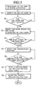
- the controller 9 takes in detection data from the paper size detector 11 to detect the size of the paper (steps S1 and S2).
- the controller 9 takes in detection data from the basis weight detector 12 to detect the basis weight of the paper (steps S3 and S4).
- the controller 9 takes in detection data from the temperature/moisture detector 15 to detect surrounding temperature and moisture (steps S5 and S6).
- the controller 9 reads applying-voltage data corresponding to the respective detection data from the applying-voltage table 9b, and then the content in the applying-voltage memory 9c is renewed to the read applying-voltage data (steps S7 and S9). Thus, the present process is ended.
- step S10 when the printing mode is started, it is detected whether or not a signal from a paper existence/non-existence sensor in the paper feeding section F changes (step S10).
- the above-mentioned detection data taking-in steps and the above-mentioned applying-voltage data renewing steps are performed (steps S11 to S18).
- the present process is ended without performing any step. That is, in the case that the paper 6 set in the paper feed section F may be new paper based on exchange, data on the paper 6 and the like are taken into prepare an appropriate applying-voltage data.
- the belt driving motor 4 is driven. By this driving power, the carrying belt 3 is moved.
- the motor 5a for the fan 5 is driven. By this driving power, the suction fan 5 is rotated.
- the paper 6 on which images have been printed on the printing section E is loaded from the paper carrying start position onto the carrying belt 3, the paper 6 is caused to adhere to the carrying belt 3 by sucking power of the suction fan 5.
- the paper 6 in this adhesive state is carried to the paper carrying end position by the movement of the carrying belt 3.
- the sucking power is controlled depending on the sort (characteristics) of the carried paper 6 because the driving power of the motor 5a for the fan 5 is adjusted by the applying-voltage data. Therefore, appropriate sucking power constantly acts depending on the sort of the paper 6 or the like so that excessive electrical power is not consumed. Moreover, there does not arise a problem that excessive load is applied to the carrying belt 3 by excessive sucking power. Therefore, excessive electrical power is not consumed in the belt driving motor 4, either.
- the first embodiment has the temperature/moisture detector 15 as a surrounding atmosphere detecting unit to make the driving power of the motor 5a for the fan 5 variable, additionally considering the temperature and the moisture of the atmosphere around the paper carrying device. For this reason, more appropriate sucking power can be caused to act so that power consumption can be more saved.
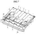
- Figs. 7 and 8 illustrate a second embodiment of the present invention.
- the second embodiment is also an embodiment wherein a paper carrying device of the present invention is applied to a paper discharge section of a stencil printing device.
- a pair of paper discharge wings 20 is located at both side ends of the three carrying belts 3. This pair of the paper discharge wings 20 is made to move upwards and downwards by driving power of a motor 21 for the wings.
- a pair of side flaps 22 is arranged inside this pair of the paper discharge wings 20. This pair of the side flaps 22 is also made to move upwards and downwards, independently from the pair of the wings 20, by driving power of the motor 21 for the wings.
- a belt roller 23 is disposed at the center of the pair of the wings 20. This belt roller 23 is also made to move upwards and downwards by driving power of the motor 21 for the wings.
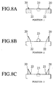
- the pair of the paper discharge wings 20, the pair of the side flaps 22, and the belt roller 23 are set into respective wing states shown in Figs. 8A,8B,8C by set values of a non-illustrated paper width detector and a non-illustrated paper feed pressure switch.
- Fig. 8A shows the state of a position 1, in which the pair of the paper discharge wings 20, the pair of the side flaps 22. and the belt roller 23 are positioned at lower positions.
- Fig. 8B shows the state of a position 2, in which the pair of the paper discharge wings 20 and the belt roller 23 are positioned at upper positions, and the pair of the side flaps 22 is positioned at a lower position.
- Fig. 8C shows the state of a position 3, in which the pair of the paper discharge wings 20 and the pair of the side flaps 22 are positioned at upper positions, and the belt roller 23 is positioned at a lower position.
- the second embodiment is made so as to have a non-illustrated carrying condition detector for detecting the set state of the wings and make driving power of a non-illustrated motor for the fan variable by means of a non-illustrated controller, under additional consideration of carrying conditions which the non-illustrated carrying condition detector detects. That is, in the second embodiment, the controller make the driving power of the non-illustrated motor for the fan variable, basically considering the characteristics of the paper, and additionally considering the surrounding temperature and moisture as well as the set wing state.
- the same effects and advantages as according to the first embodiment can be obtained.
- the driving power of the non-illustrated motor for the fan is adjusted under additional consideration of the set wing state, so that more appropriate sucking power can be caused to act.
- power consumption can be still more saved.
- the paper data detector 10 is composed of the paper size detector 11 and the basis weight detector 12 but may be composed to detect characteristics of the paper 6 by other data together with such data as above, or by data other than such data as above.
- the surrounding atmosphere detector for detecting data on the surrounding atmosphere is composed of the temperature/moisture detector 15 but may be composed to detect data on the surrounding atmosphere by other data together with such data as above, or by data other than such data as above.
- the carrying condition detector is a member for detecting the state of the wings but may be composed to detect the carrying conditions by other data together with such data as above, or by data other than such data as above.
- a paper carrying device of the present invention is applied to a paper discharge section of a stencil printing machine but may be, of course, applied to other than the paper discharge section of the stencil printing machine.
Landscapes
- Engineering & Computer Science (AREA)
- Mechanical Engineering (AREA)
- Controlling Sheets Or Webs (AREA)
- Supply, Installation And Extraction Of Printed Sheets Or Plates (AREA)
- Collation Of Sheets And Webs (AREA)
- Paper Feeding For Electrophotography (AREA)
- Inking, Control Or Cleaning Of Printing Machines (AREA)
Applications Claiming Priority (2)
| Application Number | Priority Date | Filing Date | Title |
|---|---|---|---|
| JP11197841A JP2001018512A (ja) | 1999-07-12 | 1999-07-12 | 用紙搬送装置 |
| JP19784199 | 1999-07-12 |
Publications (2)
| Publication Number | Publication Date |
|---|---|
| EP1069059A2 true EP1069059A2 (fr) | 2001-01-17 |
| EP1069059A3 EP1069059A3 (fr) | 2002-06-12 |
Family
ID=16381240
Family Applications (1)
| Application Number | Title | Priority Date | Filing Date |
|---|---|---|---|
| EP00114166A Withdrawn EP1069059A3 (fr) | 1999-07-12 | 2000-07-12 | Dispositif de transport de feuilles |
Country Status (3)
| Country | Link |
|---|---|
| US (1) | US6206591B1 (fr) |
| EP (1) | EP1069059A3 (fr) |
| JP (1) | JP2001018512A (fr) |
Cited By (4)
| Publication number | Priority date | Publication date | Assignee | Title |
|---|---|---|---|---|
| WO2010037580A3 (fr) * | 2008-09-30 | 2010-09-10 | Eastman Kodak Company | Dispositif de transport de feuilles |
| WO2012107217A3 (fr) * | 2011-02-11 | 2012-09-27 | Bdt Media Automation Gmbh | La présente invention porte sur un système d'aspiration et de transport pour aspirer et transporter un objet |
| EP2385007A3 (fr) * | 2010-05-07 | 2012-11-21 | BDT Media Automation GmbH | Système d'aspiration et de transport |
| WO2013106904A1 (fr) * | 2012-01-18 | 2013-07-25 | Liu, Mei | Dispositif de vérification et d'élimination automatique en ligne d'éléments défectueux pour presses d'impression flexographique |
Families Citing this family (6)
| Publication number | Priority date | Publication date | Assignee | Title |
|---|---|---|---|---|
| US6565171B2 (en) * | 2001-07-16 | 2003-05-20 | Hewlett-Packard Company | Method for reducing vertical banding |
| KR100441292B1 (ko) * | 2002-02-08 | 2004-07-23 | 박종환 | 인쇄기의 인쇄장치 |
| JP4495959B2 (ja) * | 2003-12-15 | 2010-07-07 | 東北リコー株式会社 | 両面印刷装置及び両面印刷方法 |
| JP4954119B2 (ja) * | 2008-02-26 | 2012-06-13 | デュプロ精工株式会社 | 排紙装置 |
| JP2014065563A (ja) * | 2012-09-25 | 2014-04-17 | Toshiba Corp | 紙葉類搬送装置 |
| US12606398B2 (en) * | 2022-08-22 | 2026-04-21 | Seiko Epson Corporation | Relay transport device, recording system, and feeding system |
Family Cites Families (7)
| Publication number | Priority date | Publication date | Assignee | Title |
|---|---|---|---|---|
| JPS552362B2 (fr) * | 1972-09-11 | 1980-01-19 | ||
| US4589652A (en) * | 1985-10-17 | 1986-05-20 | Xerox Corporation | Plural level vacuum document feeder |
| JPH04365739A (ja) * | 1991-06-08 | 1992-12-17 | Ricoh Co Ltd | 給紙装置 |
| JP3213424B2 (ja) * | 1993-02-15 | 2001-10-02 | 理想科学工業株式会社 | 孔版印刷装置の排紙装置 |
| JP3366787B2 (ja) * | 1995-10-20 | 2003-01-14 | ノーリツ鋼機株式会社 | 感光材料の吸着搬送装置 |
| JPH1035943A (ja) * | 1996-07-22 | 1998-02-10 | Canon Inc | シート材搬送装置及び画像形成装置 |
| JP3662385B2 (ja) * | 1997-04-18 | 2005-06-22 | オムロン株式会社 | 用紙搬送装置 |
-
1999
- 1999-07-12 JP JP11197841A patent/JP2001018512A/ja active Pending
-
2000
- 2000-07-10 US US09/613,144 patent/US6206591B1/en not_active Expired - Lifetime
- 2000-07-12 EP EP00114166A patent/EP1069059A3/fr not_active Withdrawn
Cited By (5)
| Publication number | Priority date | Publication date | Assignee | Title |
|---|---|---|---|---|
| WO2010037580A3 (fr) * | 2008-09-30 | 2010-09-10 | Eastman Kodak Company | Dispositif de transport de feuilles |
| EP2385007A3 (fr) * | 2010-05-07 | 2012-11-21 | BDT Media Automation GmbH | Système d'aspiration et de transport |
| EP2960191A1 (fr) | 2010-05-07 | 2015-12-30 | BDT Media Automation GmbH | Système d'aspiration et de transport |
| WO2012107217A3 (fr) * | 2011-02-11 | 2012-09-27 | Bdt Media Automation Gmbh | La présente invention porte sur un système d'aspiration et de transport pour aspirer et transporter un objet |
| WO2013106904A1 (fr) * | 2012-01-18 | 2013-07-25 | Liu, Mei | Dispositif de vérification et d'élimination automatique en ligne d'éléments défectueux pour presses d'impression flexographique |
Also Published As
| Publication number | Publication date |
|---|---|
| EP1069059A3 (fr) | 2002-06-12 |
| JP2001018512A (ja) | 2001-01-23 |
| US6206591B1 (en) | 2001-03-27 |
Similar Documents
| Publication | Publication Date | Title |
|---|---|---|
| US5415387A (en) | Sheet feed device for a selectable print speed image forming device having a time delayed pick-up roller | |
| US6206591B1 (en) | Sheet carrying device | |
| US7661670B2 (en) | Sheet discharge device | |
| JP2603358B2 (ja) | 印字装置 | |
| US20090001646A1 (en) | Image forming apparatus | |
| US6647240B2 (en) | Original feeding apparatus having a plurality of sensors | |
| JP3310107B2 (ja) | 画像形成装置及びソータ装置における制御装置 | |
| JP6958262B2 (ja) | 用紙積載装置及び画像形成システム | |
| JP5247052B2 (ja) | シート給送装置および画像形成装置 | |
| JP3547352B2 (ja) | 孔版印刷装置 | |
| JPH11130334A (ja) | シート収容装置 | |
| US20080179812A1 (en) | Inkjet image forming apparatus and method to control the same | |
| JP2001310826A (ja) | 給紙装置および給紙方法 | |
| JP2002193513A (ja) | 排紙装置及び印刷装置 | |
| JPS6218598Y2 (fr) | ||
| JPH1165193A (ja) | 用紙後処理装置 | |
| JP2000302293A (ja) | 紙葉類搬送装置、該紙葉類搬送装置を用いた印刷処理装置、紙葉類搬送方法及び印刷処理方法 | |
| JPH0224172A (ja) | 画像記録装置 | |
| JPH1087116A (ja) | シート搬送装置及びこれを備えた画像形成装置 | |
| JP2006240838A (ja) | 画像形成装置 | |
| JP2000141855A (ja) | 孔版印刷装置 | |
| JPH1144976A (ja) | 画像形成装置 | |
| JPH10164290A (ja) | プリンタ | |
| KR100359102B1 (ko) | 인쇄기용용지픽업장치의용지픽업방법 | |
| JP2006282325A (ja) | スタッカ |
Legal Events
| Date | Code | Title | Description |
|---|---|---|---|
| PUAI | Public reference made under article 153(3) epc to a published international application that has entered the european phase |
Free format text: ORIGINAL CODE: 0009012 |
|
| 17P | Request for examination filed |
Effective date: 20000712 |
|
| AK | Designated contracting states |
Kind code of ref document: A2 Designated state(s): AT BE CH CY DE DK ES FI FR GB GR IE IT LI LU MC NL PT SE |
|
| AX | Request for extension of the european patent |
Free format text: AL;LT;LV;MK;RO;SI |
|
| PUAL | Search report despatched |
Free format text: ORIGINAL CODE: 0009013 |
|
| AK | Designated contracting states |
Kind code of ref document: A3 Designated state(s): AT BE CH CY DE DK ES FI FR GB GR IE IT LI LU MC NL PT SE |
|
| AX | Request for extension of the european patent |
Free format text: AL;LT;LV;MK;RO;SI |
|
| RIC1 | Information provided on ipc code assigned before grant |
Free format text: 7B 65H 5/22 A, 7B 65H 7/16 B, 7B 65H 29/24 B |
|
| AKX | Designation fees paid |
Designated state(s): DE FR GB |
|
| 17Q | First examination report despatched |
Effective date: 20030410 |
|
| STAA | Information on the status of an ep patent application or granted ep patent |
Free format text: STATUS: THE APPLICATION IS DEEMED TO BE WITHDRAWN |
|
| 18D | Application deemed to be withdrawn |
Effective date: 20030812 |