EP1068644B1 - Speicherzellenanordnung und verfahren zu ihrer herstellung - Google Patents
Speicherzellenanordnung und verfahren zu ihrer herstellung Download PDFInfo
- Publication number
- EP1068644B1 EP1068644B1 EP99914440.5A EP99914440A EP1068644B1 EP 1068644 B1 EP1068644 B1 EP 1068644B1 EP 99914440 A EP99914440 A EP 99914440A EP 1068644 B1 EP1068644 B1 EP 1068644B1
- Authority
- EP
- European Patent Office
- Prior art keywords
- memory cell
- bit lines
- semiconductor substrate
- cell arrangement
- bars
- Prior art date
- Legal status (The legal status is an assumption and is not a legal conclusion. Google has not performed a legal analysis and makes no representation as to the accuracy of the status listed.)
- Expired - Lifetime
Links
- 238000004519 manufacturing process Methods 0.000 title description 5
- 239000004065 semiconductor Substances 0.000 claims description 44
- 238000000034 method Methods 0.000 claims description 38
- 238000002955 isolation Methods 0.000 claims description 37
- 239000000758 substrate Substances 0.000 claims description 37
- 238000005530 etching Methods 0.000 claims description 24
- 238000002513 implantation Methods 0.000 claims description 14
- 150000002500 ions Chemical class 0.000 claims 1
- 150000002736 metal compounds Chemical class 0.000 claims 1
- VYPSYNLAJGMNEJ-UHFFFAOYSA-N Silicium dioxide Chemical compound O=[Si]=O VYPSYNLAJGMNEJ-UHFFFAOYSA-N 0.000 description 18
- 229910004298 SiO 2 Inorganic materials 0.000 description 12
- 239000002019 doping agent Substances 0.000 description 10
- BOTDANWDWHJENH-UHFFFAOYSA-N Tetraethyl orthosilicate Chemical compound CCO[Si](OCC)(OCC)OCC BOTDANWDWHJENH-UHFFFAOYSA-N 0.000 description 7
- 239000000377 silicon dioxide Substances 0.000 description 7
- 239000000463 material Substances 0.000 description 6
- 229910021332 silicide Inorganic materials 0.000 description 6
- 229910052751 metal Inorganic materials 0.000 description 5
- 239000002184 metal Substances 0.000 description 5
- FVBUAEGBCNSCDD-UHFFFAOYSA-N silicide(4-) Chemical compound [Si-4] FVBUAEGBCNSCDD-UHFFFAOYSA-N 0.000 description 5
- 238000000151 deposition Methods 0.000 description 4
- 238000010586 diagram Methods 0.000 description 4
- 239000007789 gas Substances 0.000 description 4
- 239000011810 insulating material Substances 0.000 description 4
- 238000004518 low pressure chemical vapour deposition Methods 0.000 description 4
- 238000012545 processing Methods 0.000 description 4
- 229910052814 silicon oxide Inorganic materials 0.000 description 4
- XUIMIQQOPSSXEZ-UHFFFAOYSA-N Silicon Chemical compound [Si] XUIMIQQOPSSXEZ-UHFFFAOYSA-N 0.000 description 3
- 238000000137 annealing Methods 0.000 description 3
- 230000015572 biosynthetic process Effects 0.000 description 3
- 238000009792 diffusion process Methods 0.000 description 3
- 238000009413 insulation Methods 0.000 description 3
- 229910021420 polycrystalline silicon Inorganic materials 0.000 description 3
- 229910052710 silicon Inorganic materials 0.000 description 3
- 239000010703 silicon Substances 0.000 description 3
- QGZKDVFQNNGYKY-UHFFFAOYSA-N Ammonia Chemical compound N QGZKDVFQNNGYKY-UHFFFAOYSA-N 0.000 description 2
- KRHYYFGTRYWZRS-UHFFFAOYSA-N Fluorane Chemical compound F KRHYYFGTRYWZRS-UHFFFAOYSA-N 0.000 description 2
- NBIIXXVUZAFLBC-UHFFFAOYSA-N Phosphoric acid Chemical compound OP(O)(O)=O NBIIXXVUZAFLBC-UHFFFAOYSA-N 0.000 description 2
- 229910052581 Si3N4 Inorganic materials 0.000 description 2
- 229910052785 arsenic Inorganic materials 0.000 description 2
- RQNWIZPPADIBDY-UHFFFAOYSA-N arsenic atom Chemical compound [As] RQNWIZPPADIBDY-UHFFFAOYSA-N 0.000 description 2
- 238000005229 chemical vapour deposition Methods 0.000 description 2
- 239000000203 mixture Substances 0.000 description 2
- 150000004767 nitrides Chemical class 0.000 description 2
- HQVNEWCFYHHQES-UHFFFAOYSA-N silicon nitride Chemical compound N12[Si]34N5[Si]62N3[Si]51N64 HQVNEWCFYHHQES-UHFFFAOYSA-N 0.000 description 2
- 125000006850 spacer group Chemical group 0.000 description 2
- 238000003860 storage Methods 0.000 description 2
- 239000000126 substance Substances 0.000 description 2
- VLJQDHDVZJXNQL-UHFFFAOYSA-N 4-methyl-n-(oxomethylidene)benzenesulfonamide Chemical compound CC1=CC=C(S(=O)(=O)N=C=O)C=C1 VLJQDHDVZJXNQL-UHFFFAOYSA-N 0.000 description 1
- ZOXJGFHDIHLPTG-UHFFFAOYSA-N Boron Chemical compound [B] ZOXJGFHDIHLPTG-UHFFFAOYSA-N 0.000 description 1
- 229910016006 MoSi Inorganic materials 0.000 description 1
- OAICVXFJPJFONN-UHFFFAOYSA-N Phosphorus Chemical compound [P] OAICVXFJPJFONN-UHFFFAOYSA-N 0.000 description 1
- 229910008484 TiSi Inorganic materials 0.000 description 1
- 229910000147 aluminium phosphate Inorganic materials 0.000 description 1
- 229910021529 ammonia Inorganic materials 0.000 description 1
- QVGXLLKOCUKJST-UHFFFAOYSA-N atomic oxygen Chemical compound [O] QVGXLLKOCUKJST-UHFFFAOYSA-N 0.000 description 1
- 230000000903 blocking effect Effects 0.000 description 1
- 229910052796 boron Inorganic materials 0.000 description 1
- 238000006243 chemical reaction Methods 0.000 description 1
- 239000003795 chemical substances by application Substances 0.000 description 1
- 238000012217 deletion Methods 0.000 description 1
- 230000037430 deletion Effects 0.000 description 1
- 230000008021 deposition Effects 0.000 description 1
- 238000013461 design Methods 0.000 description 1
- 238000011161 development Methods 0.000 description 1
- 230000018109 developmental process Effects 0.000 description 1
- MROCJMGDEKINLD-UHFFFAOYSA-N dichlorosilane Chemical compound Cl[SiH2]Cl MROCJMGDEKINLD-UHFFFAOYSA-N 0.000 description 1
- BUMGIEFFCMBQDG-UHFFFAOYSA-N dichlorosilicon Chemical compound Cl[Si]Cl BUMGIEFFCMBQDG-UHFFFAOYSA-N 0.000 description 1
- 238000005516 engineering process Methods 0.000 description 1
- -1 for example Substances 0.000 description 1
- BHEPBYXIRTUNPN-UHFFFAOYSA-N hydridophosphorus(.) (triplet) Chemical compound [PH] BHEPBYXIRTUNPN-UHFFFAOYSA-N 0.000 description 1
- 229910021421 monocrystalline silicon Inorganic materials 0.000 description 1
- 230000003647 oxidation Effects 0.000 description 1
- 238000007254 oxidation reaction Methods 0.000 description 1
- 229910052760 oxygen Inorganic materials 0.000 description 1
- 239000001301 oxygen Substances 0.000 description 1
- 229910052698 phosphorus Inorganic materials 0.000 description 1
- 239000011574 phosphorus Substances 0.000 description 1
- 229910021340 platinum monosilicide Inorganic materials 0.000 description 1
- 238000004544 sputter deposition Methods 0.000 description 1
- 230000005641 tunneling Effects 0.000 description 1
Images


Classifications
-
- H—ELECTRICITY
- H10—SEMICONDUCTOR DEVICES; ELECTRIC SOLID-STATE DEVICES NOT OTHERWISE PROVIDED FOR
- H10B—ELECTRONIC MEMORY DEVICES
- H10B43/00—EEPROM devices comprising charge-trapping gate insulators
- H10B43/30—EEPROM devices comprising charge-trapping gate insulators characterised by the memory core region
-
- G—PHYSICS
- G11—INFORMATION STORAGE
- G11C—STATIC STORES
- G11C16/00—Erasable programmable read-only memories
- G11C16/02—Erasable programmable read-only memories electrically programmable
- G11C16/06—Auxiliary circuits, e.g. for writing into memory
-
- G—PHYSICS
- G11—INFORMATION STORAGE
- G11C—STATIC STORES
- G11C7/00—Arrangements for writing information into, or reading information out from, a digital store
- G11C7/18—Bit line organisation; Bit line lay-out
-
- H—ELECTRICITY
- H10—SEMICONDUCTOR DEVICES; ELECTRIC SOLID-STATE DEVICES NOT OTHERWISE PROVIDED FOR
- H10B—ELECTRONIC MEMORY DEVICES
- H10B69/00—Erasable-and-programmable ROM [EPROM] devices not provided for in groups H10B41/00 - H10B63/00, e.g. ultraviolet erasable-and-programmable ROM [UVEPROM] devices
Definitions
- the invention relates to a memory cell arrangement in which a plurality of memory cells are present in the area of a main area of a semiconductor substrate, wherein the memory cells each comprise at least one source, gate and drain MOS transistor, in which the memory cells are arranged in memory cell rows extending substantially parallel. in which adjacent memory cell rows are insulated by an isolation trench, in which adjacent memory cell rows each contain at least one bit line and wherein the bit lines of two adjacent memory cell rows face each other.
- the invention further relates to a method for producing this memory cell arrangement.
- Memory cells are used in wide technology areas.
- the memory cells may be read only memory referred to as ROM (Read Only Memory) as well as programmable memory called PROM (Programmable ROM).
- ROM Read Only Memory
- PROM Programmable ROM
- Memory cell arrangements on semiconductor substrates are characterized in that they allow random access to the information stored in them. They contain a variety of transistors. During the read operation, the presence or absence of a current flow through the transistor is assigned the logical states 1 or 0. Usually, the storage of the information is effected by using MOS transistors whose channel regions have a doping corresponding to the desired blocking property.
- a generic memory cell arrangement is in the U.S. Patent 5,306,941 shown.
- bit lines are arranged in the edge area of memory cell lands, the bit lines of adjacent memory cell lands facing one another.
- the bit lines are separated from one another in each case by an isolation trench filled with an insulating material.
- This document further discloses a method of manufacturing a memory cell array in which memory cell lands are formed by etching isolation trenches in a semiconductor substrate. After the etching of the isolation trenches, a diffusion of a dopant takes place, wherein bit lines are formed by the diffusion.
- a semiconductor memory is provided with a plurality of memory cells formed at the bottom of the trenches and on the lands between the trenches.
- This generic memory cell arrangement is suitable for feature sizes of at least 0.5 .mu.m and for a ROM read-only memory. An electrical programming is not possible here.
- This memory cell array includes MOS transistors arranged in rows. In each row, the MOS transistors are connected in series. To increase the storage density adjacent rows are each arranged alternately at the bottom of strip-shaped longitudinal trenches and between adjacent strip-shaped longitudinal trenches on the surface of the substrate. Connected source / drain regions are formed as a continuous doped region. By a line-by-line driving, it is possible to read this memory cell array.
- This memory cell arrangement is characterized in that the required space for the memory cells of 4 F 2 has been reduced to 2 F 2 , where F is the minimum feature width of the photolithographic process used for the production.
- F is the minimum feature width of the photolithographic process used for the production.
- the disadvantage is that a further increase in the number of memory cells per unit area is not possible here.
- the invention has for its object to overcome the disadvantages of the prior art.
- a memory cell arrangement is to be created in which the largest possible number of memory cells is arranged in the smallest possible space.
- the memory cell array should also be electrically programmable.
- isolation trench penetrates deeper into the semiconductor substrate than the bit lines and that is located below the isolation trench at least a portion of the source or the drain.
- the invention thus provides to design the memory cell array so that it contains memory cell webs, between which there are isolation trenches, which penetrate deeply into the semiconductor substrate and thus allow effective isolation of opposing bit lines.
- An electrical connection between the sources or drains of different memory cell lands is preferably made by extending a portion of the sources or drains from one memory cell land to another memory cell land.
- the sources or drains of different transistors lie in a common well.
- the memory cell array becomes electrically programmable.
- the invention further relates to a method for producing a memory cell arrangement in which insulation trenches are etched into a semiconductor substrate, so that between The isolation trenches form webs and then bit lines are generated.
- this method is carried out in such a way that channel regions are generated before the bit lines are generated, and that after the bit lines have been generated, a further etching step takes place, through which the isolation trenches penetrate deeper into the semiconductor substrate.
- a mask 15 is applied to a semiconductor substrate 10 of, for example, n-doped monocrystalline silicon having a basic dopant concentration of preferably 1 ⁇ 10 16 cm -3 to 1 ⁇ 10 17 cm -3 , for example 2 ⁇ 10 16 cm -3 .
- the mask 15 may consist of silicon oxide formed by a TEOS (Si (OC 2 H 5 ) 4 ) method. In a TEOS process, tetraethyl orthosilicate Si (OC 2 H 5 ) 4 is converted to silica SiO 2 at a temperature of about 700 degrees Celsius and a pressure in the range of 40 Pa.
- an etching process for example, a multi-stage with a gas mixture of CF 4 and O 2 or CHF 3 and O 2 and a second etching step is performed with an HBr-containing gas, so that in the semiconductor substrate 10th Form isolation trenches 20.
- an etching process for example, a multi-stage with a gas mixture of CF 4 and O 2 or CHF 3 and O 2 and a second etching step is performed with an HBr-containing gas, so that in the semiconductor substrate 10th Form isolation trenches 20.
- F is the minimum producible structure size, preferably in the range of 0.1 .mu.m to 0.5 .mu.m.
- This processing state of the semiconductor substrate is in FIG. 1 shown.
- a first dopant 22 takes place, so that side regions 25 of the webs 30 and lower bottom regions 28 of the isolation trenches 20 are p-doped.
- the side regions 25 of the webs 30 and the bottom regions 28 of the isolation trenches 20 form channel regions in the finished memory cell arrangement.
- boron is implanted at an implantation energy which is preferably of the order of 10 to 20 keV.
- the implantation dose is equal to the product of a desired concentration and the thickness of a layer to be doped and is for example 4 ⁇ 10 12 cm -2 at a preferred layer thickness of about 0.2 ⁇ m and an advantageous concentration of 2 ⁇ 10 17 cm -3 .
- the concentration of dopant in the side regions 25 and in the bottom bottom regions 28 is approximately 2 ⁇ 10 17 cm -3 .
- a bottom region 28 with two side regions 25 connected to it forms a region in which a continuous channel can form in the finished memory cell arrangement.
- This processing state of the semiconductor substrate is in FIG. 2 shown.
- a further dopant 35 so that side walls 40 of the webs 30 and upper bottom portions 50 of the insulation trenches 20 of the opposite conductivity type as the side portions 25 and the bottom portion 28 are highly doped.
- phosphorous or arsenic will be at an implantation energy which is preferably on the order of 40 to 80 keV, and at a dose in the range of 2 x 10 15 cm -2 implanted.
- the concentration of dopant in sidewalls 40 and upper floor regions 50 is approximately 2 x 10 20 cm -3 .
- This processing state of the semiconductor substrate is in FIG. 3 shown.
- the isolation trenches 20 are etched deeper and the doped upper bottom regions 50 of the isolation trenches 20 are removed.
- the mutual isolation is ensured by the fact that the isolation trenches 20 penetrate as far as possible into the substrate.
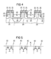
- Parts of the bit lines 60 form drains of MOS transistors in the finished memory cell arrangement.
- the bit lines 60 have a height of approximately 200 nm.
- the depth of the isolation trenches 20 is greater than the height of the bit lines 60. In this way, an effective path length 1 for a possible current path through the semiconductor substrate 10 is increased. This processing state of the semiconductor substrate is in FIG. 4 shown.
- a low-resistance connection between the sources 29 takes place, for example, via a common, not illustrated well.
- a connection can also be made, for example, via the semiconductor substrate or an electrically conductive layer.
- a typical threshold voltage of such a memory cell arrangement is approximately 0.6 V.
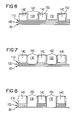
- a circuit diagram for an electrical connection of the bit lines 60 and word lines WL is shown in FIG FIG. 5 shown.
- the resistance of the bit lines 60 can be significantly reduced, preferably by a factor of 10 or more.
- the bitlines 60 are converted to a suitable silicide, ie, a metal-silicon compound.
- a suitable silicide ie, a metal-silicon compound.
- silicides such as MoSi 2 , WSi 2 , TaSi 2 , TiSi 2 , PtSi, Pd 2 Si by siliciding.
- Silica is a selective silicide formation. It is preferably carried out by sputtering on the silicide-forming metal alone and then bringing it to a silicide reaction with the bit lines as the silicon substrate. After application of the silicide-forming metal, an annealing takes place at temperatures in the range of 600 to 1000 ° C, whereby it comes to the formation of the metal silicide.
- the mask 15 is removed.
- the isolation trenches 20 are filled with an insulating material, for example with SiO 2 formed in a TEOS process. This can be done by converting tetraethyl orthosilicate: Si (OC 2 H 5 ) 4 into silica SiO 2 at a temperature of about 700 ° C and a pressure in the range of 40 Pa.
- a planarization process preferably a process of chemical-mechanical planarization.
- a suitable dielectric layer is applied to the lands 30 and the isolation trenches 20.
- the dielectric layer may preferably be formed by a multi-layer. It is particularly expedient if the dielectric layer is a triple layer, with a first dielectric Layer 90 of silicon oxide SiO 2 in a thickness of about 3 nm, a middle dielectric layer 100 of silicon nitride of about 7 to 8 nm thickness and an upper dielectric layer 110 of silicon oxide with a thickness of about 4 nm.
- the first dielectric layer 90 is formed, for example, by annealing in an O 2 -containing atmosphere in a desired layer thickness.
- the silicon of the webs 30 is converted into silica SiO 2 .
- this layer can be patterned by anisotropic etching, for example CHF 3 .
- the second dielectric layer 100 is preferably applied by a CVD (Chemical Vapor Deposition) method, in particular by an LPCVD (Low Pressure CVD) method.
- a particularly suitable variant for the formation of the second dielectric layer 100 by the LPCVD method can be carried out by adding dichlorosilane (SiH 2 CL 2 ) with the addition of ammonia (NH 3 ) at a temperature in the range of about 750 ° C. in a plasma a pressure between 10 Pa and 100 Pa, preferably 30 Pa, in silicon nitride (Si 3 N 4 ) is converted.
- the upper dielectric layer 110 is deposited by thermal oxidation, preferably in an H 2 O-containing atmosphere at a temperature around 900 ° C and a period of about 2 hours, or by any of the known film forming methods, for example, an HTO method.
- Deposition by an HTO method may preferably be carried out by converting dichlorosilane SiH 2 Cl 2 into silica SiO 2 in a N 2 O-containing atmosphere at a temperature of about 900 ° C and a pressure in the range of 40 Pa.
- a semiconductor layer 120 for example of highly doped polycrystalline silicon, is grown.
- a preferred doping of the polycrystalline Silicon is at least 10 20 cm -3 , with dopings from 10 21 cm -3 are particularly suitable.
- the semiconductor layer 120 is n + doped by diffusion or implantation of phosphorus or arsenic.
- an implantation can take place with an energy of 80 keV and a dose of 1 ⁇ 10 16 cm -2 .
- a resist mask is applied to the semiconductor layer 120.
- This is followed by an etching process, for example in several stages, with a first etching step with a gas mixture of CF 4 and O 2 or CHF 3 and O 2 and a second etching step with an HBr-containing gas.
- a first etching step with a gas mixture of CF 4 and O 2 or CHF 3 and O 2
- a second etching step with an HBr-containing gas As a result, isolation trenches 130 are etched into the semiconductor layer 120. Between the isolation trenches 130, webs 140, which serve as word lines in the finished memory cell arrangement, are formed by the remaining material of the semiconductor layer 120.
- an insulating layer 150 is deposited on the webs 140 and the isolation trenches 130 according to a suitable, most consistent method. It is particularly expedient to form the insulation layer 150 according to a TEOS method. This can be done by converting tetraethyl orthosilicate Si (OC 2 H 5 ) 4 into silica SiO 2 at a temperature of about 700 ° C and a pressure in the range of 40 Pa.
- FIG. 6 shows a section perpendicular to the in Figure 1 to 4 shown section through one of the webs 30 extends.
- an etching process is performed, wherein the nitride-containing dielectric layer 100 is removed by the application of a suitable agent, for example, phosphoric acid having a concentration in the range of 80% and a temperature around 150 ° C.
- a suitable agent for example, phosphoric acid having a concentration in the range of 80% and a temperature around 150 ° C.
- the multi-stage etching process stops on the oxide-containing lower dielectric layer 90.
- the thin dielectric layer 90 is removed in the region of the isolation trenches 130 by a further etching process, for example with a hydrofluoric acid-containing solution (HF-dip). This state of the semiconductor substrate is in FIG. 8 shown.
- HF-dip hydrofluoric acid-containing solution
- a new triple layer is grown.
- a lower dielectric layer 180, a middle dielectric layer 190 and an upper dielectric layer 200 are formed.
- the lower dielectric layer 180 is preferably made of silicon oxide SiO 2 , which is formed in a desired layer thickness, for example, in an annealing process.
- silicon oxide SiO 2 is formed in a desired layer thickness, for example, in an annealing process.
- silicon in an oxygen-containing atmosphere at a temperature of about 800 to 900 ° C in silica SiO 2 is converted.
- the middle dielectric layer 190 is preferably formed by a nitride layer formed by an LPCVD process at about 700 ° C.
- the uppermost dielectric layer 200 preferably consists of the same material as the lower dielectric layer 180, ie, in turn, preferably of SiO 2 .
- the thickness of the lower dielectric layer 180 is, for example, 3 nm in the final state, the thickness of the middle dielectric layer 190 about 7 to 8 nm and the thickness of the upper dielectric layer 200 4 nm. Such a sequence of thicknesses of the layers is particularly useful to capture To save charges as long as possible. This state of the semiconductor substrate is in FIG. 9 shown.
- the electrode layer 210 consists for example of a doped semiconductor material, preferably n-doped polycrystalline silicon, metal silicide and / or a metal.
- the semiconductor material of the electrode layer 210 may also be p-doped.
- the electrode layer 210 is formed in a thickness sufficient to fill the isolation trenches 130 between the word line forming lands 140.
- the electrode layer 210 is therefore deposited in a thickness of about 0.2 ⁇ m to 0.6 ⁇ m, preferably 0.4 ⁇ m.
- the electrode layer 210 is patterned.
- the structuring of the electrode layer 210 takes place in a multi-step process.
- the electrode layer 210 is removed by a planarization process, such as a CMP (chemical mechanical planarization) step.
- the middle dielectric layer 190 acts as a stop layer.
- the dielectric layer 170 is removed by removing its sub-layers 180, 190 and 200. Thereafter, another back etching or a process of chemical mechanical planarization (CMP) ( FIG. 10 ).
- CMP chemical mechanical planarization
- memory cells are realized by MOS transistors each consisting of a part of one of the bit lines 60 acting as a drain, the adjoining side area 25 acting as a channel region, one of the sources 29 and the dielectric layer 90, 100, 110 , which acts as a gate dielectric, and one of the webs 140, the acts as a gate electrode, or the triple layer 180, 190, 200, which acts as a gate dielectric, and a part of the patterned electrode layer 210, which acts as a gate electrode, are formed.
- the memory cell array can be produced with a spacing of the centers of gate electrodes adjacent to one of the webs 30 from a minimally manufacturable feature size F.
- the mask 15 is formed with the aid of a spacer technique, a distance of the centers of adjacent webs 30 from F is achieved. This results in a space requirement per memory cell of 0.5 x F 2 .
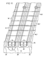
- FIG. 11 A plan view of the finished memory cell arrangement is shown in FIG. 11 shown.
- the arrangement of the bit lines 60 and of the first word lines WL 1 and second word lines WL 2 is visible.
- the first word lines WL1 and the second word lines WL 2 are formed by the webs 140 and the patterned electrode layer 210, respectively, but the structures 90, 100, 110, 130, 140, 160, 180, 190 and 210 are not shown.
- bit line 60 in the upper area of the cell array is provided with a contact 220 connected is.
- the respective other bit line 60 of the web 30 is connected in a manner not shown to the lower edge of the cell array.
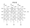
- FIG. 12 is the electrical diagram of a section of the cell array shown.
- bit lines 60, 60 ', 60 "and word lines WL 1 and WL 2 can be seen.
- Describing the memory cell 230 is done by tunneling electrical charge.
- a gate voltage of preferably 9 V to 10 V is applied to the memory cell 230 via the associated word line WL 2.
- the common sources of all the memory cells are at a common, elevated potential of, for example, 5 V.
- a drain voltage of 0 V is applied to the memory cell 230 via the bit line 60 ".On the other cells is either a gate voltage 0 or a positive drain voltage of 5, for example This avoids deleting previously described cells.
- a memory cell is preferably read such that the common sources of the memory cells are at 0 V, that the bit line belonging to the cell is at a positive potential and that the word line belonging to the cell is at a potential of, for example, 3V.
- a simultaneous deletion of all memory cells is preferably carried out in that the common sources of the cells are at 0 V, that all bit lines 60, 60 ', 60 "are at the potential 0 V and that via the word lines WL 1 and WL 2 a negative gate voltage of for example, -10V is applied.
- the invention is not limited to the described embodiments.
- the n and p dopants may be reversed.
Landscapes
- Semiconductor Memories (AREA)
- Non-Volatile Memory (AREA)
Applications Claiming Priority (3)
| Application Number | Priority Date | Filing Date | Title |
|---|---|---|---|
| DE19812948 | 1998-03-24 | ||
| DE19812948 | 1998-03-24 | ||
| PCT/DE1999/000762 WO1999049516A1 (de) | 1998-03-24 | 1999-03-17 | Speicherzellenanordnung und verfahren zu ihrer herstellung |
Publications (2)
| Publication Number | Publication Date |
|---|---|
| EP1068644A1 EP1068644A1 (de) | 2001-01-17 |
| EP1068644B1 true EP1068644B1 (de) | 2015-07-08 |
Family
ID=7862152
Family Applications (1)
| Application Number | Title | Priority Date | Filing Date |
|---|---|---|---|
| EP99914440.5A Expired - Lifetime EP1068644B1 (de) | 1998-03-24 | 1999-03-17 | Speicherzellenanordnung und verfahren zu ihrer herstellung |
Country Status (7)
| Country | Link |
|---|---|
| US (2) | US6365944B1 (enExample) |
| EP (1) | EP1068644B1 (enExample) |
| JP (1) | JP2002508594A (enExample) |
| KR (1) | KR100623144B1 (enExample) |
| CN (1) | CN1165999C (enExample) |
| TW (1) | TW432700B (enExample) |
| WO (1) | WO1999049516A1 (enExample) |
Families Citing this family (10)
| Publication number | Priority date | Publication date | Assignee | Title |
|---|---|---|---|---|
| WO2000054335A1 (en) | 1999-03-09 | 2000-09-14 | Koninklijke Philips Electronics N.V. | Semiconductor device comprising a non-volatile memory |
| JP4730999B2 (ja) * | 2000-03-10 | 2011-07-20 | スパンション エルエルシー | 不揮発性メモリの製造方法 |
| DE10051483A1 (de) * | 2000-10-17 | 2002-05-02 | Infineon Technologies Ag | Nichtflüchtige Halbleiterspeicherzellenanordnung und Verfahren zu deren Herstellung |
| US6580120B2 (en) * | 2001-06-07 | 2003-06-17 | Interuniversitair Microelektronica Centrum (Imec Vzw) | Two bit non-volatile electrically erasable and programmable memory structure, a process for producing said memory structure and methods for programming, reading and erasing said memory structure |
| US6630384B1 (en) * | 2001-10-05 | 2003-10-07 | Advanced Micro Devices, Inc. | Method of fabricating double densed core gates in sonos flash memory |
| JP3967193B2 (ja) * | 2002-05-21 | 2007-08-29 | スパンション エルエルシー | 不揮発性半導体記憶装置及びその製造方法 |
| US7423310B2 (en) * | 2004-09-29 | 2008-09-09 | Infineon Technologies Ag | Charge-trapping memory cell and charge-trapping memory device |
| US7786512B2 (en) * | 2005-07-18 | 2010-08-31 | Saifun Semiconductors Ltd. | Dense non-volatile memory array and method of fabrication |
| KR100739532B1 (ko) | 2006-06-09 | 2007-07-13 | 삼성전자주식회사 | 매몰 비트라인 형성 방법 |
| US8441063B2 (en) * | 2010-12-30 | 2013-05-14 | Spansion Llc | Memory with extended charge trapping layer |
Family Cites Families (10)
| Publication number | Priority date | Publication date | Assignee | Title |
|---|---|---|---|---|
| US4651184A (en) * | 1984-08-31 | 1987-03-17 | Texas Instruments Incorporated | Dram cell and array |
| JP2596198B2 (ja) | 1990-08-30 | 1997-04-02 | 日本電気株式会社 | Mos型読み出し専用半導体記憶装置 |
| JPH05102436A (ja) * | 1991-10-09 | 1993-04-23 | Ricoh Co Ltd | 半導体メモリ装置とその製造方法 |
| US5278438A (en) | 1991-12-19 | 1994-01-11 | North American Philips Corporation | Electrically erasable and programmable read-only memory with source and drain regions along sidewalls of a trench structure |
| DE19510042C2 (de) | 1995-03-20 | 1997-01-23 | Siemens Ag | Festwert-Speicherzellenanordnung und Verfahren zu deren Herstellung |
| DE19514834C1 (de) * | 1995-04-21 | 1997-01-09 | Siemens Ag | Festwertspeicherzellenanordnung und Verfahren zu deren Herstellung |
| KR0179807B1 (ko) * | 1995-12-30 | 1999-03-20 | 문정환 | 반도체 기억소자 제조방법 |
| KR100215840B1 (ko) * | 1996-02-28 | 1999-08-16 | 구본준 | 반도체 메모리셀 구조 및 제조방법 |
| US6118147A (en) * | 1998-07-07 | 2000-09-12 | Advanced Micro Devices, Inc. | Double density non-volatile memory cells |
| US6207493B1 (en) * | 1998-08-19 | 2001-03-27 | International Business Machines Corporation | Formation of out-diffused bitline by laser anneal |
-
1999
- 1999-03-17 CN CNB998044148A patent/CN1165999C/zh not_active Expired - Fee Related
- 1999-03-17 KR KR1020007010546A patent/KR100623144B1/ko not_active Expired - Fee Related
- 1999-03-17 JP JP2000538387A patent/JP2002508594A/ja active Pending
- 1999-03-17 EP EP99914440.5A patent/EP1068644B1/de not_active Expired - Lifetime
- 1999-03-17 WO PCT/DE1999/000762 patent/WO1999049516A1/de not_active Ceased
- 1999-03-22 TW TW088104477A patent/TW432700B/zh not_active IP Right Cessation
-
2000
- 2000-09-25 US US09/668,485 patent/US6365944B1/en not_active Expired - Lifetime
-
2001
- 2001-12-03 US US10/005,978 patent/US6534362B2/en not_active Expired - Lifetime
Also Published As
| Publication number | Publication date |
|---|---|
| WO1999049516A1 (de) | 1999-09-30 |
| US6365944B1 (en) | 2002-04-02 |
| KR100623144B1 (ko) | 2006-09-12 |
| US20020055247A1 (en) | 2002-05-09 |
| US6534362B2 (en) | 2003-03-18 |
| JP2002508594A (ja) | 2002-03-19 |
| EP1068644A1 (de) | 2001-01-17 |
| CN1294759A (zh) | 2001-05-09 |
| KR20010042141A (ko) | 2001-05-25 |
| TW432700B (en) | 2001-05-01 |
| CN1165999C (zh) | 2004-09-08 |
Similar Documents
| Publication | Publication Date | Title |
|---|---|---|
| DE3788172T2 (de) | MIS integrierte Schaltung, wie eine EPROM-Speicherzelle, und Verfahren zu deren Herstellung. | |
| DE10129958B4 (de) | Speicherzellenanordnung und Herstellungsverfahren | |
| DE2502235C2 (enExample) | ||
| DE19808182C1 (de) | Elektrisch programmierbare Speicherzellenanordnung und ein Verfahren zu deren Herstellung | |
| DE4016686C2 (de) | Verfahren zum Herstellen eines Halbleiterspeichers | |
| DE10110150A1 (de) | Verfahren zum Herstellen von metallischen Bitleitungen für Speicherzellenarrays, Verfahren zum Herstellen von Speicherzellenarrays und Speicherzellenarray | |
| DE3134110A1 (de) | Integrierte halbleiterschaltung | |
| DE69018690T2 (de) | Verfahren zur Herstellung einer EPROM-Zellen-Matrize. | |
| DE19845004C2 (de) | DRAM-Zellenanordnung und Verfahren zu deren Herstellung | |
| EP1068644B1 (de) | Speicherzellenanordnung und verfahren zu ihrer herstellung | |
| DE102006040584A1 (de) | Halbleiterprodukt und Verfahren zur Herstellung eines Halbleiterprodukts | |
| EP1125328B1 (de) | Verfahren zur herstellung einer dram-zellenanordnung | |
| DE19646419C1 (de) | Verfahren zur Herstellung einer elektrisch schreib- und löschbaren Festwertspeicherzellenanordnung | |
| EP1129482A1 (de) | Verfahren zur Herstellung von einer DRAM-Zellenanordnung | |
| DE10226964A1 (de) | Verfahren zur Herstellung einer NROM-Speicherzellenanordnung | |
| DE10229065A1 (de) | Verfahren zur Herstellung eines NROM-Speicherzellenfeldes | |
| EP0864177B1 (de) | Festwert-speicherzellenanordnung und verfahren zu deren herstellung | |
| DE10225410A1 (de) | Verfahren zur Herstellung von NROM-Speicherzellen mit Grabentransistoren | |
| EP0899783B1 (de) | Schaltungsanordnung mit mindestens vier Transistoren und Verfahren zu dessen Herstellung | |
| EP1068645B1 (de) | Speicherzellenanordnung und verfahren zu ihrer herstellung | |
| DD280851A1 (de) | Verfahren zur herstellung von graben-speicherzellen | |
| EP0924767B1 (de) | EEPROM-Anordnung und Verfahren zu deren Herstellung | |
| DE19604260C2 (de) | Festwert-Speicherzellenvorrichtung und ein Verfahren zu deren Herstellung | |
| DE102005038939B4 (de) | Halbleiterspeicherbauelement mit oberseitig selbstjustiert angeordneten Wortleitungen und Verfahren zur Herstellung von Halbleiterspeicherbauelementen | |
| DE102006019122B4 (de) | Verfahren zur Herstellung einer integrierten Speichervorrichtung mit vergrabenen Bitleitungen und integrierte Speichervorrichtung mit vergrabenen Bitleitungen |
Legal Events
| Date | Code | Title | Description |
|---|---|---|---|
| PUAI | Public reference made under article 153(3) epc to a published international application that has entered the european phase |
Free format text: ORIGINAL CODE: 0009012 |
|
| 17P | Request for examination filed |
Effective date: 20000711 |
|
| AK | Designated contracting states |
Kind code of ref document: A1 Designated state(s): DE FR GB IE IT |
|
| RAP1 | Party data changed (applicant data changed or rights of an application transferred) |
Owner name: INFINEON TECHNOLOGIES AG |
|
| RAP1 | Party data changed (applicant data changed or rights of an application transferred) |
Owner name: QIMONDA AG |
|
| RAP1 | Party data changed (applicant data changed or rights of an application transferred) |
Owner name: INFINEON TECHNOLOGIES AG |
|
| RIC1 | Information provided on ipc code assigned before grant |
Ipc: H01L 27/115 20060101AFI20141212BHEP |
|
| GRAP | Despatch of communication of intention to grant a patent |
Free format text: ORIGINAL CODE: EPIDOSNIGR1 |
|
| RIC1 | Information provided on ipc code assigned before grant |
Ipc: H01L 21/8246 20060101ALI20150115BHEP Ipc: G11C 16/06 20060101ALI20150115BHEP Ipc: H01L 27/112 20060101AFI20150115BHEP Ipc: H01L 27/115 20060101ALI20150115BHEP |
|
| INTG | Intention to grant announced |
Effective date: 20150128 |
|
| GRAS | Grant fee paid |
Free format text: ORIGINAL CODE: EPIDOSNIGR3 |
|
| GRAA | (expected) grant |
Free format text: ORIGINAL CODE: 0009210 |
|
| AK | Designated contracting states |
Kind code of ref document: B1 Designated state(s): DE FR GB IE IT |
|
| REG | Reference to a national code |
Ref country code: GB Ref legal event code: FG4D Free format text: NOT ENGLISH |
|
| REG | Reference to a national code |
Ref country code: DE Ref legal event code: R081 Ref document number: 59915431 Country of ref document: DE Owner name: POLARIS INNOVATIONS LIMITED, IE Free format text: FORMER OWNER: INFINEON TECHNOLOGIES AG, 81669 MUENCHEN, DE |
|
| REG | Reference to a national code |
Ref country code: IE Ref legal event code: FG4D Free format text: LANGUAGE OF EP DOCUMENT: GERMAN |
|
| REG | Reference to a national code |
Ref country code: DE Ref legal event code: R096 Ref document number: 59915431 Country of ref document: DE |
|
| RAP2 | Party data changed (patent owner data changed or rights of a patent transferred) |
Owner name: POLARIS INNOVATIONS LIMITED |
|
| REG | Reference to a national code |
Ref country code: FR Ref legal event code: PLFP Year of fee payment: 18 |
|
| REG | Reference to a national code |
Ref country code: DE Ref legal event code: R097 Ref document number: 59915431 Country of ref document: DE |
|
| PG25 | Lapsed in a contracting state [announced via postgrant information from national office to epo] |
Ref country code: IT Free format text: LAPSE BECAUSE OF FAILURE TO SUBMIT A TRANSLATION OF THE DESCRIPTION OR TO PAY THE FEE WITHIN THE PRESCRIBED TIME-LIMIT Effective date: 20150708 |
|
| PLBE | No opposition filed within time limit |
Free format text: ORIGINAL CODE: 0009261 |
|
| STAA | Information on the status of an ep patent application or granted ep patent |
Free format text: STATUS: NO OPPOSITION FILED WITHIN TIME LIMIT |
|
| PGFP | Annual fee paid to national office [announced via postgrant information from national office to epo] |
Ref country code: GB Payment date: 20160321 Year of fee payment: 18 Ref country code: FR Payment date: 20160321 Year of fee payment: 18 |
|
| 26N | No opposition filed |
Effective date: 20160411 |
|
| PGFP | Annual fee paid to national office [announced via postgrant information from national office to epo] |
Ref country code: DE Payment date: 20160512 Year of fee payment: 18 |
|
| REG | Reference to a national code |
Ref country code: IE Ref legal event code: MM4A |
|
| PG25 | Lapsed in a contracting state [announced via postgrant information from national office to epo] |
Ref country code: IE Free format text: LAPSE BECAUSE OF NON-PAYMENT OF DUE FEES Effective date: 20160317 |
|
| REG | Reference to a national code |
Ref country code: DE Ref legal event code: R082 Ref document number: 59915431 Country of ref document: DE Representative=s name: ZIMMERMANN & PARTNER PATENTANWAELTE MBB, DE Ref country code: DE Ref legal event code: R081 Ref document number: 59915431 Country of ref document: DE Owner name: POLARIS INNOVATIONS LIMITED, IE Free format text: FORMER OWNER: INFINEON TECHNOLOGIES AG, 85579 NEUBIBERG, DE |
|
| REG | Reference to a national code |
Ref country code: DE Ref legal event code: R119 Ref document number: 59915431 Country of ref document: DE |
|
| GBPC | Gb: european patent ceased through non-payment of renewal fee |
Effective date: 20170317 |
|
| REG | Reference to a national code |
Ref country code: FR Ref legal event code: ST Effective date: 20171130 |
|
| PG25 | Lapsed in a contracting state [announced via postgrant information from national office to epo] |
Ref country code: DE Free format text: LAPSE BECAUSE OF NON-PAYMENT OF DUE FEES Effective date: 20171003 Ref country code: FR Free format text: LAPSE BECAUSE OF NON-PAYMENT OF DUE FEES Effective date: 20170331 |
|
| PG25 | Lapsed in a contracting state [announced via postgrant information from national office to epo] |
Ref country code: GB Free format text: LAPSE BECAUSE OF NON-PAYMENT OF DUE FEES Effective date: 20170317 |