EP1067999B1 - Flüssigkeitsfilter - Google Patents
Flüssigkeitsfilter Download PDFInfo
- Publication number
- EP1067999B1 EP1067999B1 EP99911588A EP99911588A EP1067999B1 EP 1067999 B1 EP1067999 B1 EP 1067999B1 EP 99911588 A EP99911588 A EP 99911588A EP 99911588 A EP99911588 A EP 99911588A EP 1067999 B1 EP1067999 B1 EP 1067999B1
- Authority
- EP
- European Patent Office
- Prior art keywords
- liquid
- filter according
- liquid filter
- collecting space
- channel
- Prior art date
- Legal status (The legal status is an assumption and is not a legal conclusion. Google has not performed a legal analysis and makes no representation as to the accuracy of the status listed.)
- Expired - Lifetime
Links
Images


Classifications
-
- F—MECHANICAL ENGINEERING; LIGHTING; HEATING; WEAPONS; BLASTING
- F01—MACHINES OR ENGINES IN GENERAL; ENGINE PLANTS IN GENERAL; STEAM ENGINES
- F01M—LUBRICATING OF MACHINES OR ENGINES IN GENERAL; LUBRICATING INTERNAL COMBUSTION ENGINES; CRANKCASE VENTILATING
- F01M11/00—Component parts, details or accessories, not provided for in, or of interest apart from, groups F01M1/00 - F01M9/00
- F01M11/03—Mounting or connecting of lubricant purifying means relative to the machine or engine; Details of lubricant purifying means
Definitions
- the invention relates to a liquid filter according to the preamble of claim 1.
- Such a filter is known from EP 0 492 627 A2.
- the reception room is self-contained there, so that penetrating into it Liquid cannot flow outside.
- a liquid filter is known from the publication WO 97/16234 Cleaning oil or fuel known to an engine block an internal combustion engine is flanged.
- the filter's existing plastic housing is cylindrical Filter body arranged, the raw side with contaminated Liquid that is supplied via an inlet channel is acted upon becomes.
- the outflow space of the filter body is one Return channel connected through which the cleaned liquid can be removed from the filter housing.
- the inlet channel encloses the return channel ring-shaped, the outer wall of the inlet channel formed by the outer wall of the filter housing is.
- the front connections of the inlet and the Return channel are via seals in mounts on the engine block used.
- the liquid to be cleaned is under pressure by the Inlet channel led to the filter body.
- the seals made of very high quality and expensive material his.
- even small leaks cause a strong one Pressure drop so that the one required for filtration Minimum pressure not applied and the filtration was not carried out can be.
- the invention is based on the problem, with little effort also in the case of a reliable and low-maintenance, generic Form plastic liquid filter in which due to material and / or manufacturing errors unintentionally under high pressure liquid in a larger volume penetrates into the collecting space as this space without increasing the pressure can record.
- the generic filter in one Form designed to be a constructively rational integration additional functional parts such as one in particular Cooler for the liquid to be filtered as well as pressure sensors allows.
- the inlet channel and the return channel are in a collecting room with a safety wall that is part of the filter housing is and radially encloses the inlet channel and the return channel.
- a connection flange for example an engine block of an internal combustion engine, connected
- safety is increased in the event of leaky seals, because both the incoming raw liquid and the outflowing pure liquid double sealed against the environment are: within the inlet or the return channel and also inside the collecting room, the wall of which little effort liquid-tight connected to the connecting flange can be. It can also penetrate into the collecting space Drain liquid through the drain provided there, which ensures an unintentionally high pressure in the collecting space is avoided.
- the pressure in the collecting space is limited to the pressure at its drain opening.
- the collecting room can be designed for atmospheric pressure.
- the Overpressure in the supplied or removed liquid flow is completely absorbed by the inlet and return channels.
- the collecting room remains unaffected by this, it acts as a safety reservoir in the event that leakages occur. hereby need to the seal between the security wall and the connecting flange no increased quality requirements be put, that is, for example, a simple one O-ring seal can be used.
- the plastic filter housing can be injection molded in a cast with sufficient dimensional accuracy, so that post-processing is no longer necessary. Moreover a significant weight advantage is achieved.
- the one in the filter housing trained channels can be made relatively thick-walled to absorb the pressures in the liquid; at the same time, the security wall can be made thin-walled as there is no overpressure in the collecting area.
- connections of the inlet channel and the return channel are advantageous provided with a radial seal to prevent pressure and liquid-tight seal between the filter housing and the connection flange.
- Holding forces acting in the axial direction are essentially about the security wall of the pressure-free collecting space and in particular via more trained Fastening domes, where appropriate metal bushings are added, transmitted so that the channels of high axial forces are relieved and an undesirable creep behavior of the plastic in the area of the channels is avoided.
- the radial seals are preferably spherical to axial To be able to compensate for tolerances.
- the collecting area By connecting the collecting area with a drainage channel, is about this liquid that leaked into the catchment area is, for example, leaky radial seals from the Inlet channel or return channel, derived from the collecting space, especially in the oil pan of the internal combustion engine. How already explained above prevents the Collection area full of liquid and itself an overpressure builds up in the collecting room.
- the drain channel runs in the connection flange and is via a recess in the connection flange connected to the collecting room.
- a pressure relief valve can also be provided in the collecting space be acted upon by the pressure on the clean side of the filter becomes and when a limit pressure is exceeded Collection room opens and thereby relieves pressure. The liquid that escapes into the collecting space becomes again derived from the collecting space via the drainage channel.
- the end faces of the channels expediently end in one different axial distance, also a housing holder, in which the pressure relief valve can be used. hereby assembly is made easier by the filter housing with an almost constant axial assembly force is placed on the connecting flange and one after the other first the most protruding component and then the less protruding parts in corresponding Recordings are used in the connecting flange. This also prevents the filter housing tilted during assembly.
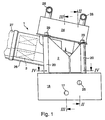
- the liquid filter 1, which is appropriate for filtering oil or fuel in an internal combustion engine is used with the plastic Filter housing 2 on a connecting flange 18, in particular an engine block of an internal combustion engine, placed.
- the Liquid to be cleaned is overpressured via the connection flange 18 through a raw liquid line 25 over an inlet channel in the filter housing 2 first one above the filter 1 arranged oil cooler 24 supplied and then passed through a filter body 3, which is in a lateral, radially outward cylindrical Section 26 of the filter housing 2 is located. After Cleaning flows the pure liquid through a return channel in the filter housing 2 back into a clean line 17 in the connecting flange 18th
- the cylindrical section 26 with the filter body 3 is from a removable cover 27 closed.
- the filter housing 2, the connecting flange 18 and the oil cooler 24 are over Screws 29 held together in fastening domes 20, which are formed in one piece with the filter housing are; to increase the stability can in the mounting domes 20 metal bushings are injected.
- On the oil cooler 24 are connections 28 for the supply and discharge of heat exchange medium arranged. The oil cooler 24 contributes to stabilization and gain of filter 1 at.
- Fig. 2 is the supply of the unpurified liquid in the Remove filter housing 2.
- the unpurified liquid flows over the radially inward raw liquid line 25 in the connecting flange 18 to a recess in Connection flange 18, in which the vertical inlet channel 4 is inserted in the filter housing 2.
- a radial seal 10 arranged by means of a liquid-tight seal between the inlet channel 4 and the recess in the connecting flange 18 is created.
- the radial seal 10 is preferred spherical to compensate for axial tolerances.
- a return check valve 19 is arranged in the inlet channel 4, to reflux the liquid to be cleaned back in to prevent the raw liquid line 25.
- the raw liquid continues to flow upwards in the direction of the arrow into the oil cooler 24, in which the liquid is tempered, i.e. is cooled or warmed depending on the application.
- the oil cooler 24 In the area the connection of the oil filter 24 to the inlet channel 4 a radial seal 34 is arranged.
- the inlet channel 4 lies in an annular collecting space 6 with a safety wall 7, which is part of the filter housing 2 and radially encloses the inlet channel 4.
- the reception room 6 is designed without pressure and is in connection with a recess 30 in the connecting flange 18, which in radial running drainage channels 23 opens, which to the oil pan Lead internal combustion engine.
- the drain channels 23 can be parallel run and have different diameters.
- the end face 12 of the safety wall 7 engages in one circular recess on the top of the connection flange 18 a, in the area of the end face 12 of the security wall 7 between the wall of the recess and the safety wall an O-ring seal 13 is arranged to to seal the collecting space 6 in a liquid-tight manner from the surroundings.
- Fig. 3 is the derivation of the liquid from the filter housing 2 can be seen.
- the liquid in the oil cooler 24 is the liquid in the filter body in the cylindrical Section 26 of the filter housing 2 supplied.
- Filtration flows the cleaned liquid out of the radial internal flow space 33 of the filter body in the return channel 5, which is formed in the filter housing 2 and extends in the vertical direction.
- the return duct 5 has a radial seal 11 in the area of its connection 9 on, which protrudes into a recess 31 in the connecting flange 18 and the return channel 5 with the connecting flange 18 pressure and fluid-tight connection.
- the recess 31 opens into a horizontally running pure line 17, via which the cleaned Liquid is guided radially out of the connecting flange 18 and for example when using oil as a liquid can be used to lubricate bearings.
- a connector 22 projects radially into the return channel 5, via which the pressure in the return channel 5 is a pressure sensor 21 and can be fed to a turbocharger connection.
- the connector 22 is inserted into a socket 35 and sealed in this nozzle via a radial seal 36.
- the attachment of the connector 22 to the socket 35 can be achieved by a bayonet lock. It is for that only required that on the connector 22 and the Stub 35 interlocking bayonet locking means are provided.
- the bayonet lock can in particular, be designed in such a way that it locks the bayonet locking means without these against each other to twist, can be closed.
- the connector 22 is used for fixation of the return channel 5.
- the connection between the Return channel 5 and the connecting piece 22 is done by that at one end of the annular wall of the return channel 5 axial slot 37 is provided in which one of the connector 22 outgoing fitting snap-like can be inserted.
- connection between the connector 22 and the nozzle 35 on the one hand and between the return channel 5 and the connector 22 on the other hand are only in the subject of the invention Sliding connections that are easy to manufacture available.
- Sliding connections that are easy to manufacture available.
- a sliding connection with a radial seal and a bayonet lock can also be used for the pressure sensor 2 connected to the connector 22 in an advantageous manner his.
- Other functional parts can also be used in the same way be connected to the filter housing in a fluid-carrying manner.
- a pressure relief valve 15 is arranged parallel to the return duct 5, that in one piece with the filter housing 2 trained housing receptacle 16 sits. When closed closes the pressure relief valve 15 with the collecting space 6 communicating recess 32 in the connecting flange 18, which connects the collecting space 6 to the pure line 17, so that when the pressure relief valve 15 is closed, the connection interrupted between the pure line 17 and the collecting space 6 is. Above a limit pressure in the pure line 17 opens the pressure relief valve 15 by the in the closed position spring-loaded valve body of the pressure relief valve 15 backs away and the connection between the recess 32nd and the collecting space 6 releases, so that liquid from the Pure line 17 can flow into the collecting space 6 and a Overpressure in the pure line 17 is reduced.
- the in the Collection space 6 escaping liquid can be removed via the in FIG illustrated recess communicating with the collecting space 6 Drain 30 in the connecting flange 18.
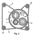
- the return channel 5, the housing receptacle 16 and the in Fig. 2 shown inlet channel 4 run parallel to each other.
- the safety wall 7 lies within an outer wall of the housing 14.
- the fastening domes 20 mark corner points in the outer wall 14; there are a total of four fastening domes 20 provided that together form a rectangle.
Landscapes
- Engineering & Computer Science (AREA)
- Mechanical Engineering (AREA)
- General Engineering & Computer Science (AREA)
- Lubrication Details And Ventilation Of Internal Combustion Engines (AREA)
- Filtration Of Liquid (AREA)
Description
- Fig. 1
- eine Seitenansicht eines Flüssigkeitsfilters,
- Fig. 2
- eine Ansicht gemäß Schnittlinie II-II aus Fig. 1,
- Fig. 3
- eine Ansicht gemäß Schnittlinie III-III aus Fig. 1,
- Fig. 4
- eine Ansicht gemäß Schnittlinie IV-IV aus Fig. 1.
Claims (14)
- Flüssigkeitsfilter, insbesondere Öl- oder Kraftstoffilter in einer Brennkraftmaschine, mit einem in einem Filtergehäuse (2) aus Kunststoff aufgenommenen Filterkörper (3), einem Rohflüssigkeit zuführenden Zulaufkanal (14), einem Reinflüssigkeit abführenden Rücklaufkanal (5) zum dichten Aufsetzen auf einen Anschlußflansch (18), wobei der Zulaufkanal (4) und der Rücklaufkanal (5) in einem Auffangraum (6) des Filtergehäuses angeordnet sind und der Auffangraum (6) von einer den Zulaufkanal (4) und den Rücklaufkanal (5) radial umgreifenden, einteilig mit dem Filtergehäuse (2) ausgebildeten, gegenüber dem Anschlußflansch (18) mittels einer Dichtung (13) zu dichtenden Sicherheitswandung (7) begrenzt ist,
dadurch gekennzeichnet, daß der Auffangraum (6) einen Ablaufkanal (23) besitzt. - Flüssigkeitsfilter nach Anspruch 1,
dadurch gekennzeichnet, daß im Auffangraum (6) ein mit einer in dem Anschlußflansch (18) vorgesehenen Reinleitung (17) kommunizierendes Überdruckventil (15) angeordnet ist, das zum Auffangraum (6) hin öffnet. - Flüssigkeitsfilter nach Anspruch 1 oder 2,
dadurch gekennzeichnet, daß im Bereich der Anschlüsse (8, 9) des Zulaufkanals (4) und des Rücklaufkanals (5) jeweils eine Radialdichtung (10, 11) angeordnet ist. - Flüssigkeitsfilter nach Anspruch 3,
dadurch gekennzeichnet, daß die Radialdichtungen (10, 11) ballig ausgeführt sind. - Flüssigkeitsfilter nach einem der vorhergehenden Ansprüche,
dadurch gekennzeichnet, daß die mit der Sicherheitswandung (7) zusammenwirkende Dichtung (13) im Bereich der offenen Stirnseite (12) der Sicherheitswandung (7) wirkt. - Flüssigkeitsfilter nach einem der vorhergehenden Ansprüche,
dadurch gekennzeichnet, daß das Überdruckventil (15) in einer Gehäuseaufnahme (16) des Filtergehäuses (2) gehalten ist. - Flüssigkeitsfilter nach einem der vorhergehenden Ansprüche,
dadurch gekennzeichnet, daß die Kanäle (4, 5) bzw. die Gehäuseaufnahme (16) im Bereich des Auffangraumes (6) etwa parallel verlaufen. - Flüssigkeitsfilter nach einem der vorhergehenden Ansprüche,
dadurch gekennzeichnet, daß im Zulaufkanal (4) ein Rücklauf-Sperrventil (19) angeordnet ist. - Flüssigkeitsfilter nach einem der vorhergehenden Ansprüche,
dadurch gekennzeichnet, daß das Filtergehäuse (2) verstärkt ausgebildete Befestigungsdome (20) aufweist. - Flüssigkeitsfilter nach Anspruch 9,
dadurch gekennzeichnet, daß in den Befestigungsdomen (20) Metallbuchsen aufgenommen sind. - Flüssigkeitsfilter nach einem der vorhergehenden Ansprüche,
dadurch gekennzeichnet, daß ein Drucksensor (21) zur Ermittlung des Drucks im Rücklaufkanal (5) vorgesehen ist. - Flüssigkeitsfilter nach Anspruch 11,
dadurch gekennzeichnet, daß ein mit dem Rücklaufkanal (5) verbundenes Anschlußstück (22) zur Aufnahme des Drucksensors (21) angeordnet ist. - Flüssigkeitsfilter nach einem der vorhergehenden Ansprüche,
dadurch gekennzeichnet, daß dem Filter (1) ein Ölkühler (24) zur Kühlung der zu reinigenden Flüssigkeit zugeordnet ist. - Flüssigkeitsfilter nach Anspruch 13,
dadurch gekennzeichnet, daß die Befestigung des Filtergehäuses (2) zugleich als Befestigung des Ölkühlers (24) dient.
Applications Claiming Priority (3)
| Application Number | Priority Date | Filing Date | Title |
|---|---|---|---|
| DE19804329A DE19804329A1 (de) | 1998-02-04 | 1998-02-04 | Flüssigkeitsfilter |
| DE19804329 | 1998-02-04 | ||
| PCT/DE1999/000332 WO1999039802A1 (de) | 1998-02-04 | 1999-02-01 | Flüssigkeitsfilter |
Publications (4)
| Publication Number | Publication Date |
|---|---|
| EP1067999A1 EP1067999A1 (de) | 2001-01-17 |
| EP1067999B1 true EP1067999B1 (de) | 2002-01-16 |
| EP1067999B2 EP1067999B2 (de) | 2004-07-28 |
| EP1067999B9 EP1067999B9 (de) | 2005-01-05 |
Family
ID=7856597
Family Applications (1)
| Application Number | Title | Priority Date | Filing Date |
|---|---|---|---|
| EP99911588A Expired - Lifetime EP1067999B9 (de) | 1998-02-04 | 1999-02-01 | Flüssigkeitsfilter |
Country Status (5)
| Country | Link |
|---|---|
| US (1) | US6379537B1 (de) |
| EP (1) | EP1067999B9 (de) |
| DE (2) | DE19804329A1 (de) |
| ES (1) | ES2172312T3 (de) |
| WO (1) | WO1999039802A1 (de) |
Families Citing this family (11)
| Publication number | Priority date | Publication date | Assignee | Title |
|---|---|---|---|---|
| DE29915384U1 (de) * | 1999-09-02 | 2001-01-18 | Ing. Walter Hengst GmbH & Co. KG, 48147 Münster | Kombination aus einer Haupteinheit und wenigstens einer Anbau-Funktionseinheit |
| DE19951084A1 (de) * | 1999-10-23 | 2001-04-26 | Mahle Filtersysteme Gmbh | Flüssigkeitsfilter, insbesondere Ölfilter |
| DE10012461A1 (de) | 2000-03-15 | 2001-09-20 | Mahle Filtersysteme Gmbh | Flüssigkeitsfilter, insbesondere Ölfilter |
| US6591807B1 (en) * | 2000-08-25 | 2003-07-15 | Walter Hengst Gmbh & Co Kg | Combination comprising a main unit and at least one add-on functional unit |
| DE20108573U1 (de) * | 2001-05-21 | 2002-10-02 | Ing. Walter Hengst GmbH & Co. KG, 48147 Münster | Flüssigkeitsfilter mit einem Träger aus einem zweiten Werkstoff |
| DE20312318U1 (de) * | 2003-08-09 | 2004-12-16 | Hengst Gmbh & Co.Kg | Flüssigkeitsfilter für eine Brennkraftmaschine |
| US20070080106A1 (en) * | 2005-10-12 | 2007-04-12 | Kohler Co. | Oil filter housing |
| JP4889541B2 (ja) * | 2007-03-28 | 2012-03-07 | 本田技研工業株式会社 | 車両用内燃機関 |
| US8534424B2 (en) * | 2008-09-10 | 2013-09-17 | Ford Global Technologies, Llc | Automotive turbocharger with integral lubricating oil filter |
| US10052577B2 (en) | 2016-02-17 | 2018-08-21 | Caterpillar Inc. | Self-cleaning oil filter housing |
| US10648509B2 (en) | 2017-05-30 | 2020-05-12 | Itt Manufacturing Enterprises Llc. | Oil filter/liquid indicator assembly |
Citations (12)
| Publication number | Priority date | Publication date | Assignee | Title |
|---|---|---|---|---|
| GB958345A (en) * | 1961-12-27 | 1964-05-21 | Alpura Ag | Seals for pipe joints and the like |
| DE1916325A1 (de) * | 1969-03-29 | 1970-10-08 | Babcock & Wilcox Ag | Abdichtung von Hochdruckarmaturen und selbstdichtendem Deckelverschluss mit Spindelstopfbuchse |
| DE2141051A1 (de) * | 1971-08-17 | 1973-02-22 | Ahlborn E Ag | Ventil |
| DE2505544C2 (de) * | 1975-02-10 | 1981-09-17 | Leonhard Schleicher Südmo-Armaturenfabrik GmbH, 7081 Riesbürg | Ventil mit Leckageanzeige |
| DE9301373U1 (de) * | 1993-02-02 | 1993-03-11 | Böllhoff & Co GmbH & Co KG, 4800 Bielefeld | In einer Bohrung zu verankernde Verstärkungshülse |
| EP0328551B1 (de) * | 1986-11-04 | 1994-03-23 | Osmonics, Inc. | Flüssigkeitsfilter mit trocken bleibendem gehäuse |
| DE4242997C1 (de) * | 1992-12-18 | 1994-04-14 | Hengst Walter Gmbh & Co Kg | Brennkraftmaschine mit einem Ölfilter für deren Schmieröl |
| DE4306431C1 (de) * | 1993-03-02 | 1994-07-28 | Hengst Walter Gmbh & Co Kg | Vorrichtung zum Abtrennen von Verunreinigungen aus dem Schmieröl einer Brennkraftmaschine |
| DE29610290U1 (de) * | 1996-06-12 | 1996-08-22 | Ing. Walter Hengst GmbH & Co KG, 48147 Münster | Flüssigkeitsfilter |
| DE19536219C1 (de) * | 1995-09-28 | 1996-11-07 | Siemens Ag | Hydraulikleitung mit integriertem, drucklosem Rücklauf |
| WO1997016234A1 (de) * | 1995-10-27 | 1997-05-09 | Ing. Walter Hengst Gmbh & Co. Kg | Flüssigkeitsfilter, insbesondere für öl oder kraftstoff einer brennkraftmaschine, und dazu passender maschinenseitiger filteranschlussflansch |
| DE69311480T2 (de) * | 1992-09-25 | 1998-01-22 | Plastic Omnium Cie | Doppelt gesichertes Rohrsystem und Lecksuchverfahren |
Family Cites Families (16)
| Publication number | Priority date | Publication date | Assignee | Title |
|---|---|---|---|---|
| US1896310A (en) | 1929-12-11 | 1933-02-07 | William R Hildebrand | Water filter |
| US3759388A (en) * | 1971-09-08 | 1973-09-18 | G Thomason | Filtering system for deep fat cooking vessel |
| DE8014780U1 (de) † | 1980-06-03 | 1980-09-25 | Sartorius Gmbh, 3400 Goettingen | Mehrteiliges filtergehaeuse zur aufnahme von mehreren patronenfoermigen filterelementen |
| DE3027994A1 (de) * | 1980-07-24 | 1982-02-25 | Daimler-Benz Ag, 7000 Stuttgart | Filter fuer dieselkraftstoff |
| FR2610059B1 (fr) * | 1987-01-23 | 1990-12-07 | Renault | Dispositif de differentiel |
| US4857189A (en) * | 1988-10-13 | 1989-08-15 | Everpure, Inc. | Filter cartridge with a lugged concentric closure portion |
| DE4035181A1 (de) * | 1990-11-06 | 1992-05-07 | Bosch Gmbh Robert | Fluessigkeitsfilter |
| JPH04225806A (ja) | 1990-12-27 | 1992-08-14 | Kanebo Ltd | 二重構造フィルタ容器 |
| US5090871A (en) † | 1991-02-12 | 1992-02-25 | Systems Chemistry, Inc. | Junction assembly with leak detection means |
| DE9407889U1 (de) * | 1994-05-12 | 1994-07-14 | Couwenbergs, Paul, 76189 Karlsruhe | Vorrichtung zum Filtern von verunreinigten Flüssigkeiten |
| GB9601286D0 (en) * | 1996-01-23 | 1996-03-27 | Sev Trent Water Ltd | Screening fluid flows |
| GB2309397B (en) | 1996-01-25 | 2000-08-02 | Mann & Hummel Filter | Oil filter |
| FR2745196B1 (fr) * | 1996-02-23 | 1998-05-15 | Filtrauto | Filtre a cartouche amovible pour moteur a combustion interne |
| JP3389010B2 (ja) * | 1996-07-02 | 2003-03-24 | 愛三工業株式会社 | 燃料フィルタ |
| DE19635777A1 (de) * | 1996-09-04 | 1998-03-05 | Mann & Hummel Filter | Baugruppe für eine Verbrennungskraftmaschine |
| US5858224A (en) * | 1997-03-18 | 1999-01-12 | Nelson Industries, Inc. | Filter with pressure sensor mounted in housing end |
-
1998
- 1998-02-04 DE DE19804329A patent/DE19804329A1/de not_active Withdrawn
-
1999
- 1999-02-01 EP EP99911588A patent/EP1067999B9/de not_active Expired - Lifetime
- 1999-02-01 US US09/601,066 patent/US6379537B1/en not_active Expired - Fee Related
- 1999-02-01 WO PCT/DE1999/000332 patent/WO1999039802A1/de not_active Ceased
- 1999-02-01 ES ES99911588T patent/ES2172312T3/es not_active Expired - Lifetime
- 1999-02-01 DE DE59900637T patent/DE59900637D1/de not_active Expired - Lifetime
Patent Citations (12)
| Publication number | Priority date | Publication date | Assignee | Title |
|---|---|---|---|---|
| GB958345A (en) * | 1961-12-27 | 1964-05-21 | Alpura Ag | Seals for pipe joints and the like |
| DE1916325A1 (de) * | 1969-03-29 | 1970-10-08 | Babcock & Wilcox Ag | Abdichtung von Hochdruckarmaturen und selbstdichtendem Deckelverschluss mit Spindelstopfbuchse |
| DE2141051A1 (de) * | 1971-08-17 | 1973-02-22 | Ahlborn E Ag | Ventil |
| DE2505544C2 (de) * | 1975-02-10 | 1981-09-17 | Leonhard Schleicher Südmo-Armaturenfabrik GmbH, 7081 Riesbürg | Ventil mit Leckageanzeige |
| EP0328551B1 (de) * | 1986-11-04 | 1994-03-23 | Osmonics, Inc. | Flüssigkeitsfilter mit trocken bleibendem gehäuse |
| DE69311480T2 (de) * | 1992-09-25 | 1998-01-22 | Plastic Omnium Cie | Doppelt gesichertes Rohrsystem und Lecksuchverfahren |
| DE4242997C1 (de) * | 1992-12-18 | 1994-04-14 | Hengst Walter Gmbh & Co Kg | Brennkraftmaschine mit einem Ölfilter für deren Schmieröl |
| DE9301373U1 (de) * | 1993-02-02 | 1993-03-11 | Böllhoff & Co GmbH & Co KG, 4800 Bielefeld | In einer Bohrung zu verankernde Verstärkungshülse |
| DE4306431C1 (de) * | 1993-03-02 | 1994-07-28 | Hengst Walter Gmbh & Co Kg | Vorrichtung zum Abtrennen von Verunreinigungen aus dem Schmieröl einer Brennkraftmaschine |
| DE19536219C1 (de) * | 1995-09-28 | 1996-11-07 | Siemens Ag | Hydraulikleitung mit integriertem, drucklosem Rücklauf |
| WO1997016234A1 (de) * | 1995-10-27 | 1997-05-09 | Ing. Walter Hengst Gmbh & Co. Kg | Flüssigkeitsfilter, insbesondere für öl oder kraftstoff einer brennkraftmaschine, und dazu passender maschinenseitiger filteranschlussflansch |
| DE29610290U1 (de) * | 1996-06-12 | 1996-08-22 | Ing. Walter Hengst GmbH & Co KG, 48147 Münster | Flüssigkeitsfilter |
Also Published As
| Publication number | Publication date |
|---|---|
| US6379537B1 (en) | 2002-04-30 |
| EP1067999A1 (de) | 2001-01-17 |
| ES2172312T3 (es) | 2002-09-16 |
| DE59900637D1 (de) | 2002-02-21 |
| EP1067999B9 (de) | 2005-01-05 |
| DE19804329A1 (de) | 1999-08-05 |
| EP1067999B2 (de) | 2004-07-28 |
| WO1999039802A1 (de) | 1999-08-12 |
Similar Documents
| Publication | Publication Date | Title |
|---|---|---|
| EP1295025B1 (de) | Flüssigkeitskreislauf | |
| DE102004041408B4 (de) | Kraftstoffabgabesysteme | |
| DE102010064620B4 (de) | Filtervorrichtung | |
| EP1342003B1 (de) | Vorrichtung zur kraftstoffversorgung einer brennkraftmaschine mit einem kraftstoffilter | |
| EP1242747A1 (de) | Filtervorrichtung eines hydrauliksystems | |
| EP1198682B1 (de) | Schnellkupplung für das öffnen eines ventils | |
| EP1067999B2 (de) | Flüssigkeitsfilter | |
| DE2827022A1 (de) | Wasserbehaelter als reservedruckbehaelter | |
| DE69712444T2 (de) | Brennstoffpumpenmodul für Brennstofftank eines Fahrzeugs | |
| DE69820939T2 (de) | Pumpvorrichtung und Kraftfahrzeug mit einer solchen Vorrichtung | |
| WO2018054474A1 (de) | Hydrauliktank und verfahren zur herstellung eines hydrauliktanks | |
| DE102009032572A1 (de) | Filtereinrichtung | |
| DE2512077A1 (de) | Gemeinsamer ablass und vorrichtung fuer das schmiersystem eines motors | |
| DE3214688A1 (de) | Fluegelradpumpe | |
| DE102009030500B4 (de) | Flüssigkeitsfiltersystem eines Flüssigkeitskreislaufs | |
| DE69926000T2 (de) | Ölablassschranke | |
| DE102005057710B4 (de) | Wechselölfilter mit federbetätigtem Dorn für Ablauf | |
| DE3048301A1 (de) | Filterverbindungsstueck fuer kraftfahrzeugfilter | |
| EP1870570A2 (de) | Einrichtung mit einem Wärmetauscher und einem Flüssigkeitsfilter | |
| DE102019213522A1 (de) | Getriebeölmodul für eine Getriebeeinrichtung | |
| DE202004017745U1 (de) | Kühlmittel-Pflege-Einheit mit Rücklaufsperrventil | |
| DE102009048588A1 (de) | Filtereinrichtung, insbesondere zur Flüssigkeitsfilterung in Brennkraftmaschinen | |
| DE69612804T2 (de) | Schraubenverdichter | |
| DE102011076961A1 (de) | Filter- und Kühlvorrichtung | |
| EP1090666A1 (de) | Flüssigkeitsfilter mit Schlauchstutzen als Anschluss |
Legal Events
| Date | Code | Title | Description |
|---|---|---|---|
| PUAI | Public reference made under article 153(3) epc to a published international application that has entered the european phase |
Free format text: ORIGINAL CODE: 0009012 |
|
| 17P | Request for examination filed |
Effective date: 20000405 |
|
| AK | Designated contracting states |
Kind code of ref document: A1 Designated state(s): DE ES FR GB |
|
| GRAG | Despatch of communication of intention to grant |
Free format text: ORIGINAL CODE: EPIDOS AGRA |
|
| GRAG | Despatch of communication of intention to grant |
Free format text: ORIGINAL CODE: EPIDOS AGRA |
|
| GRAH | Despatch of communication of intention to grant a patent |
Free format text: ORIGINAL CODE: EPIDOS IGRA |
|
| 17Q | First examination report despatched |
Effective date: 20010619 |
|
| GRAH | Despatch of communication of intention to grant a patent |
Free format text: ORIGINAL CODE: EPIDOS IGRA |
|
| GRAA | (expected) grant |
Free format text: ORIGINAL CODE: 0009210 |
|
| REG | Reference to a national code |
Ref country code: GB Ref legal event code: IF02 |
|
| AK | Designated contracting states |
Kind code of ref document: B1 Designated state(s): DE ES FR GB |
|
| REF | Corresponds to: |
Ref document number: 59900637 Country of ref document: DE Date of ref document: 20020221 |
|
| GBT | Gb: translation of ep patent filed (gb section 77(6)(a)/1977) |
Effective date: 20020407 |
|
| ET | Fr: translation filed | ||
| REG | Reference to a national code |
Ref country code: ES Ref legal event code: FG2A Ref document number: 2172312 Country of ref document: ES Kind code of ref document: T3 |
|
| PLBI | Opposition filed |
Free format text: ORIGINAL CODE: 0009260 |
|
| PLBQ | Unpublished change to opponent data |
Free format text: ORIGINAL CODE: EPIDOS OPPO |
|
| PLBF | Reply of patent proprietor to notice(s) of opposition |
Free format text: ORIGINAL CODE: EPIDOS OBSO |
|
| 26 | Opposition filed |
Opponent name: HENGST FILTERWERKE ING. WALTER HENGST GMBH & CO. K Effective date: 20021012 |
|
| PLBF | Reply of patent proprietor to notice(s) of opposition |
Free format text: ORIGINAL CODE: EPIDOS OBSO |
|
| RAP2 | Party data changed (patent owner data changed or rights of a patent transferred) |
Owner name: MAHLE FILTERSYSTEME GMBH Owner name: DAIMLERCHRYSLER AG |
|
| PGFP | Annual fee paid to national office [announced via postgrant information from national office to epo] |
Ref country code: ES Payment date: 20040210 Year of fee payment: 6 |
|
| REG | Reference to a national code |
Ref country code: GB Ref legal event code: 732E |
|
| RIN2 | Information on inventor provided after grant (corrected) |
Inventor name: MUERWALD, MARIO Inventor name: FREY, JUERGEN Inventor name: LAYER, MARKUS Inventor name: BRIEDEN, THOMAS |
|
| PUAH | Patent maintained in amended form |
Free format text: ORIGINAL CODE: 0009272 |
|
| STAA | Information on the status of an ep patent application or granted ep patent |
Free format text: STATUS: PATENT MAINTAINED AS AMENDED |
|
| 27A | Patent maintained in amended form |
Effective date: 20040728 |
|
| AK | Designated contracting states |
Kind code of ref document: B2 Designated state(s): DE ES FR GB |
|
| GBTA | Gb: translation of amended ep patent filed (gb section 77(6)(b)/1977) | ||
| PG25 | Lapsed in a contracting state [announced via postgrant information from national office to epo] |
Ref country code: ES Free format text: LAPSE BECAUSE OF FAILURE TO SUBMIT A TRANSLATION OF THE DESCRIPTION OR TO PAY THE FEE WITHIN THE PRESCRIBED TIME-LIMIT Effective date: 20041108 |
|
| ET3 | Fr: translation filed ** decision concerning opposition | ||
| REG | Reference to a national code |
Ref country code: GB Ref legal event code: 732E Free format text: REGISTERED BETWEEN 20090528 AND 20090603 |
|
| REG | Reference to a national code |
Ref country code: FR Ref legal event code: TP Ref country code: FR Ref legal event code: CD |
|
| PGFP | Annual fee paid to national office [announced via postgrant information from national office to epo] |
Ref country code: FR Payment date: 20140226 Year of fee payment: 16 |
|
| PGFP | Annual fee paid to national office [announced via postgrant information from national office to epo] |
Ref country code: GB Payment date: 20140228 Year of fee payment: 16 |
|
| PGFP | Annual fee paid to national office [announced via postgrant information from national office to epo] |
Ref country code: DE Payment date: 20140430 Year of fee payment: 16 |
|
| REG | Reference to a national code |
Ref country code: DE Ref legal event code: R119 Ref document number: 59900637 Country of ref document: DE |
|
| GBPC | Gb: european patent ceased through non-payment of renewal fee |
Effective date: 20150201 |
|
| REG | Reference to a national code |
Ref country code: FR Ref legal event code: ST Effective date: 20151030 |
|
| PG25 | Lapsed in a contracting state [announced via postgrant information from national office to epo] |
Ref country code: DE Free format text: LAPSE BECAUSE OF NON-PAYMENT OF DUE FEES Effective date: 20150901 Ref country code: GB Free format text: LAPSE BECAUSE OF NON-PAYMENT OF DUE FEES Effective date: 20150201 |
|
| PG25 | Lapsed in a contracting state [announced via postgrant information from national office to epo] |
Ref country code: FR Free format text: LAPSE BECAUSE OF NON-PAYMENT OF DUE FEES Effective date: 20150302 |