EP1067319A2 - Dispositif de commande pour actionneur de transmission - Google Patents
Dispositif de commande pour actionneur de transmission Download PDFInfo
- Publication number
- EP1067319A2 EP1067319A2 EP00109135A EP00109135A EP1067319A2 EP 1067319 A2 EP1067319 A2 EP 1067319A2 EP 00109135 A EP00109135 A EP 00109135A EP 00109135 A EP00109135 A EP 00109135A EP 1067319 A2 EP1067319 A2 EP 1067319A2
- Authority
- EP
- European Patent Office
- Prior art keywords
- pressure medium
- pressure
- valve
- controllable valve
- controllable
- Prior art date
- Legal status (The legal status is an assumption and is not a legal conclusion. Google has not performed a legal analysis and makes no representation as to the accuracy of the status listed.)
- Granted
Links
Images
Classifications
-
- F—MECHANICAL ENGINEERING; LIGHTING; HEATING; WEAPONS; BLASTING
- F16—ENGINEERING ELEMENTS AND UNITS; GENERAL MEASURES FOR PRODUCING AND MAINTAINING EFFECTIVE FUNCTIONING OF MACHINES OR INSTALLATIONS; THERMAL INSULATION IN GENERAL
- F16H—GEARING
- F16H61/00—Control functions within control units of change-speed- or reversing-gearings for conveying rotary motion ; Control of exclusively fluid gearing, friction gearing, gearings with endless flexible members or other particular types of gearing
- F16H61/26—Generation or transmission of movements for final actuating mechanisms
- F16H61/28—Generation or transmission of movements for final actuating mechanisms with at least one movement of the final actuating mechanism being caused by a non-mechanical force, e.g. power-assisted
- F16H61/2807—Generation or transmission of movements for final actuating mechanisms with at least one movement of the final actuating mechanism being caused by a non-mechanical force, e.g. power-assisted using electric control signals for shift actuators, e.g. electro-hydraulic control therefor
-
- F—MECHANICAL ENGINEERING; LIGHTING; HEATING; WEAPONS; BLASTING
- F16—ENGINEERING ELEMENTS AND UNITS; GENERAL MEASURES FOR PRODUCING AND MAINTAINING EFFECTIVE FUNCTIONING OF MACHINES OR INSTALLATIONS; THERMAL INSULATION IN GENERAL
- F16H—GEARING
- F16H59/00—Control inputs to control units of change-speed-, or reversing-gearings for conveying rotary motion
- F16H59/68—Inputs being a function of gearing status
- F16H2059/6807—Status of gear-change operation, e.g. clutch fully engaged
-
- F—MECHANICAL ENGINEERING; LIGHTING; HEATING; WEAPONS; BLASTING
- F16—ENGINEERING ELEMENTS AND UNITS; GENERAL MEASURES FOR PRODUCING AND MAINTAINING EFFECTIVE FUNCTIONING OF MACHINES OR INSTALLATIONS; THERMAL INSULATION IN GENERAL
- F16H—GEARING
- F16H59/00—Control inputs to control units of change-speed-, or reversing-gearings for conveying rotary motion
- F16H59/68—Inputs being a function of gearing status
- F16H2059/683—Sensing pressure in control systems or in fluid controlled devices, e.g. by pressure sensors
-
- F—MECHANICAL ENGINEERING; LIGHTING; HEATING; WEAPONS; BLASTING
- F16—ENGINEERING ELEMENTS AND UNITS; GENERAL MEASURES FOR PRODUCING AND MAINTAINING EFFECTIVE FUNCTIONING OF MACHINES OR INSTALLATIONS; THERMAL INSULATION IN GENERAL
- F16H—GEARING
- F16H61/00—Control functions within control units of change-speed- or reversing-gearings for conveying rotary motion ; Control of exclusively fluid gearing, friction gearing, gearings with endless flexible members or other particular types of gearing
- F16H61/26—Generation or transmission of movements for final actuating mechanisms
- F16H61/28—Generation or transmission of movements for final actuating mechanisms with at least one movement of the final actuating mechanism being caused by a non-mechanical force, e.g. power-assisted
- F16H2061/2823—Controlling actuator force way characteristic, i.e. controlling force or movement depending on the actuator position, e.g. for adapting force to synchronisation and engagement of gear clutch
-
- F—MECHANICAL ENGINEERING; LIGHTING; HEATING; WEAPONS; BLASTING
- F16—ENGINEERING ELEMENTS AND UNITS; GENERAL MEASURES FOR PRODUCING AND MAINTAINING EFFECTIVE FUNCTIONING OF MACHINES OR INSTALLATIONS; THERMAL INSULATION IN GENERAL
- F16H—GEARING
- F16H61/00—Control functions within control units of change-speed- or reversing-gearings for conveying rotary motion ; Control of exclusively fluid gearing, friction gearing, gearings with endless flexible members or other particular types of gearing
- F16H61/26—Generation or transmission of movements for final actuating mechanisms
- F16H61/28—Generation or transmission of movements for final actuating mechanisms with at least one movement of the final actuating mechanism being caused by a non-mechanical force, e.g. power-assisted
- F16H61/30—Hydraulic or pneumatic motors or related fluid control means therefor
- F16H2061/305—Accumulators for fluid supply to the servo motors, or control thereof
-
- F—MECHANICAL ENGINEERING; LIGHTING; HEATING; WEAPONS; BLASTING
- F16—ENGINEERING ELEMENTS AND UNITS; GENERAL MEASURES FOR PRODUCING AND MAINTAINING EFFECTIVE FUNCTIONING OF MACHINES OR INSTALLATIONS; THERMAL INSULATION IN GENERAL
- F16H—GEARING
- F16H61/00—Control functions within control units of change-speed- or reversing-gearings for conveying rotary motion ; Control of exclusively fluid gearing, friction gearing, gearings with endless flexible members or other particular types of gearing
- F16H61/26—Generation or transmission of movements for final actuating mechanisms
- F16H61/28—Generation or transmission of movements for final actuating mechanisms with at least one movement of the final actuating mechanism being caused by a non-mechanical force, e.g. power-assisted
- F16H61/30—Hydraulic or pneumatic motors or related fluid control means therefor
-
- Y—GENERAL TAGGING OF NEW TECHNOLOGICAL DEVELOPMENTS; GENERAL TAGGING OF CROSS-SECTIONAL TECHNOLOGIES SPANNING OVER SEVERAL SECTIONS OF THE IPC; TECHNICAL SUBJECTS COVERED BY FORMER USPC CROSS-REFERENCE ART COLLECTIONS [XRACs] AND DIGESTS
- Y10—TECHNICAL SUBJECTS COVERED BY FORMER USPC
- Y10T—TECHNICAL SUBJECTS COVERED BY FORMER US CLASSIFICATION
- Y10T74/00—Machine element or mechanism
- Y10T74/19—Gearing
- Y10T74/19219—Interchangeably locked
- Y10T74/19251—Control mechanism
Definitions
- the invention relates to a device for controlling a Actuator for a transmission according to the genus of Claims 1, 7 and 8.
- Such a device is from DE 33 15 221 C2 known.
- the known device has a first controllable valve device and a second controllable valve device on which a first pressure medium chamber and a second pressure medium chamber of an actuating device either with a pressure medium source or with a Pressure medium sink are connectable.
- the actuator has a piston with a piston rod, the Piston from the pressure medium in the pressure medium chambers in the direction its longitudinal axis can be driven.
- the piston rod is via a lever with a shift shaft of a transmission connected.
- the facility has a holding device for the Gearshift shaft on.
- a controllable Valve device is the holding device optional with the pressure medium source or with the pressure medium sink connectable.
- the controllable valve devices are included an electrical control device electrically connected.
- the holding device is first by applying pressure medium to their release position brought. Then by controlling Pressure medium in a pressure medium chamber of the actuating device the one that is operatively connected to the gearshift shaft Actuator piston driven. Shortly before the selector shaft has reached the desired position, the holding device is vented by the force a spring of the holding device reaches part of the Holding device in a position in which the Holding device brakes the switching times. At the same time the pressure medium supply to the pressure medium chamber Actuator interrupted. If the leap is the has reached the desired position, it is held by the holding device fixed in this position. Switching the holding device from the release position in the Braking or stopping position and interrupting the pressure medium supply to the pressure medium chamber of the actuating device takes place depending on the position or also depending from the running speed of the selector shaft of the transmission.
- the invention has for its object a device for controlling an actuator for a transmission to create that can be made with simple means leaves.
- the invention has the particular advantage of having simple Average the actuating force of the actuating device depending on the pressure to be able to control.
- the device according to the invention has a simple Build on and is inexpensive to manufacture.
- the device is the pressure medium connection a pressure sensor device consisting of only one pressure sensor connected to a pressure medium line, which the pressure medium input of a first controllable Valve device and the pressure medium inlet of a second controllable valve device for the actuating device with the pressure medium outlet of a third controllable Valve device connects the pressure medium inlet with a pressure medium source is connected. That’s it possible with only one pressure sensor both the height of the Pressure in each of the two pressure medium chambers Actuator to measure as well as the level of the supply pressure to monitor for the actuator.
- the pressure medium inputs of two further valve devices which one of the two pressure medium chambers are assigned to the second actuating device with the pressure medium line connected which is the pressure medium outlet the third valve device with the pressure medium inputs of the two valve devices of the first actuating device and connects the pressure sensor device.
- the actuator is arranged a throttle.
- the Throttle prevents the during a control phase Pressure at the pressure sensor device to the level of Supply pressure increases. The one occurring at the pressure sensor Pressure therefore corresponds more to the pressure in a pressure medium chamber the actuating device.
- the actuating device is advantageously equipped with a Travel sensor equipped so that the piston of the actuator depending on the signals from the displacement sensor can be brought into any predeterminable position.
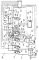
- the figure shows a simplified setup for Control a transmission.
- the device has a first double-acting cylinder and a second double-acting cylinder on, with the first cylinder as one first actuating device (1) and the second working cylinder serves as a second actuating device (6).
- the first Actuating device (1) has a first pressure medium chamber (2) and a second pressure medium chamber (5) through which a piston (3) movable in the direction of its longitudinal axis are separated from each other.
- a sealing ring On the circumference of the piston (3) a sealing ring, not shown, is arranged, the sealingly rests on the wall of the actuating device.
- Piston (3) is centrally used as an actuator (4) Piston rod arranged.
- the second actuating device (6) has a first pressure medium chamber (7) and a second Pressure medium chamber (10) by one in the direction its longitudinal axis movable piston (8) separated from each other are. There is no circumference of the piston (8) shown sealing ring arranged, the sealing on the Wall of the actuator is present. One as an actuator (9) serving piston rod is arranged centrally on the piston (8).
- the first actuating device (1) is used for Moving the gear wheels of the gear on the gear shaft and the second adjusting device (6) is used for displacement of the shift finger or the shift shaft in the Shift gate of the transmission.
- the first pressure medium chamber (2) of the first actuating device (1) via a pressure medium line (35) with a Pressure medium outlet (34) of a first controllable valve device (30) connected.
- the second pressure chamber (5) of the first actuating device (1) is above a Pressure medium line (40) with a pressure medium outlet (41) a second controllable valve device (42) in connection.
- a pressure medium line (29) connects one Pressure medium inlet (32) of the first valve device (30) with a pressure medium inlet (38) of the second valve device (42).
- a branching part (28) and one Pressure medium line (27) is the pressure medium line (29) on the one hand to a pressure medium outlet (25) as a shut-off valve serving third controllable valve device (23) and on the other hand to a pressure medium connection a pressure sensor device formed by a pressure sensor (36) connected.
- a throttle (26) is arranged between the pressure medium outlet (25) of the third valve device (23) and the branching part (28) is in the pressure medium line (27) a throttle (26) is arranged.
- a pressure medium inlet (24) of the third valve device (23) is via a pressure medium line with a supply line serving pressure medium line (18) connected.
- the pressure medium line (18) is at the pressure medium outlet one serving as a pressure generating device Pressure medium pump (49) and via one of the pressure medium line (18) branching pressure medium line (44) to one Pressure fluid accumulator (43) connected.
- the pressure fluid reservoir (43) stands over the pressure medium line (44) with a pressure control valve (46) in connection. Your pressure medium outlet the pressure medium pump (49) is in the direction check valve to be blocked on the pressure medium pump (49) (71) downstream.
- An input of the pressure medium pump (49) via a fluid line (66) with a also serves as a pressure medium sink (51) for a liquid medium, such as. Hydraulic oil, connected.
- a motor drives the pressure medium pump (49) (48).
- a pressure medium outlet (33) of the first valve device (30) is a pressure medium line (31) and one with this connected further pressure medium line (17) with the Container (51) in connection.
- a pressure medium outlet (39) of the second valve device (42) a pressure medium line (37), which is also connected to the pressure medium line (17) is connected to the container (51) connected.
- a pressure sensor (47) connected to monitor the supply pressure serves.
- the first valve device (30) and the second valve device (42) are as 3/2-way solenoid valves educated.
- the third valve device (23) is as 2/2-way solenoid valve designed.
- About electrical Lines (22, 21, 69) are the electromagnets of the three valve devices (30, 42, 23) with the associated Outputs of an electrical control device (52) electrically connected.
- the pressure sensor device (36) and the pressure sensor (47) are via electrical lines (59, 68) with assigned inputs of the electrical control device (52) electrically connected.
- clutch cylinder (61) For connecting the input shaft of the gearbox with a Output shaft of a motor, not shown, is used clutch cylinder (61) which can be actuated by pressure medium.
- the clutch cylinder (61) is via intake and exhaust valve means (56, 53) optionally with the pressure medium source (43, 49) or with the one serving as a pressure medium sink Container (51) connectable or lockable against both.
- the inlet and outlet valve means (56, 53) exist from a first 2/2-way solenoid valve (56) and a second 2/2-way solenoid valve (53) which over electrical lines (57, 58) associated with them Outputs of the electrical control device (52) connected are.
- the pressure medium inlet of the first 2/2-way solenoid valve (56) stands over a pressure medium line (45) with the pressure medium line serving as supply line (18) in connection.
- the pressure medium outlet this solenoid valve (56) is via a pressure medium line (54) and a pressure medium line connected to this (55) with a pressure medium chamber of the clutch cylinder (61) connected.
- the fluid lines (54, 55) also serve to connect the pressure medium chamber the clutch cylinder (61) with the pressure medium inlet of the second 2/2-way solenoid valve (53).
- the pressure medium outlet of this solenoid valve (53) is via a pressure medium line (50) and with this connected pressure medium line (17) with the as Pressure medium sink serving container (51) connected.
- On displacement sensor (70) assigned to the clutch cylinder (61) to measure the clutch travel is an electrical Line (60) with an input of the electrical Control device (52) in connection.
- the piston (3) or the actuator (4) as a double-acting Working cylinder trained first actuator (1) is also a displacement sensor (64) for recording of the piston (3) or the actuator (4) Path -measuring the travel-assigned.
- the Travel sensor (64) is connected to an electrical line (62) an input of the electrical control device (52) connected.
- the motor (48) for driving the pressure medium pump (49) is an electrical line (67) an output of the electrical control device (52) in Connection.
- the first pressure medium chamber (7) of the second mentioned Actuating device (6) is via a pressure medium line (12) with the pressure medium outlet as a 3/2-way solenoid valve trained first controllable valve device (14) connected.
- the pressure medium inlet of the first valve device (14) is via a pressure medium line (16) with the supply line Pressure medium line (18) in connection.
- the pressure medium outlet the first valve device (14) is via a Pressure medium line (15) with that leading to the pressure medium sink Pressure medium line (17) connected.
- the second Pressure medium chamber (10) of the second actuating device (6) is via a pressure medium line (11) with the pressure medium outlet one designed as a 3/2-way solenoid valve second controllable valve device (13) connected.
- the pressure medium inlet of the second valve device (13) is with that serving as supply line Pressure medium line (18) connected.
- the pressure medium outlet the second valve device (13) is above the pressure medium line (17) in connection with the pressure fluid sink.
- the solenoids of these two solenoid valves (14, 13) are via electrical lines (19, 20) with associated outputs of the electrical control device (52) connected.
- One of the piston (8) or the Actuator (9) assigned to the second actuating device (6) Travel sensor (65) for measuring the travel is protruding an electrical line (63) with an input of the electrical Control device (52) in connection.
- the means for controlling a gearbox arranged in a motor vehicle In the position of the first valve device (30) shown and the second valve device (42) of the first actuating device (1) are the pressure medium chambers (2, 5) first adjusting device (1) against that of the pressure medium pump (49) and the pressure medium accumulator (43) Blocked pressure medium source (43, 49) and with the container (51) for hydraulic oil (pressure medium sink) connected.
- the upstream of the two valve devices (30, 42) third valve device serving as a shut-off valve (23) is switched to continuity.
- the two pressure medium chambers (7, 10) are also the second actuating device (6) by means of those assigned to it controllable valve devices (14, 13) against the pressure medium source (43, 49) shut off and with the container (51) connected.
- the clutch cylinder (61) is by means of the two controllable valve devices assigned to it (56, 53) against the pressure medium source (43, 49) and locked against the container (51).
- a gear of the transmission is to be engaged, from a switching stage selector, not shown a corresponding signal to the electrical control device (52) given. From the electrical control device (52) are then in a given order the associated with the clutch cylinder (61) as Inlet valve serving valve means (56) which the second actuating device (6) assigned first valve device (14) and that of the first actuating device (1) assigned first valve device (30) electrically controlled.
- the assigned to the clutch cylinder (61) as Valve device (56) serving the inlet valve then arrives in their open position.
- the clutch cylinder (61) will pressurized, whereby the clutch in their release position is brought.
- the first valve device (14) becomes the second Actuator (6) switched so that the first Pressure medium chamber (7) of the second actuating device (6) shut off against the pressure medium sink and with the pressure medium source (43, 49) is connected.
- the piston (8) of the second actuating device (6) serving as a lane cylinder is from the pressure medium in the direction of the second pressure medium chamber (10) moved too.
- The is about Actuator (9) with the piston (8) connected shift fingers or the shift shaft of the transmission in the shift gate shifted until this one or a predetermined one Has reached position.
- output signal recognizes the electrical control device (52) that the shift finger or the shift shaft has reached the desired position.
- the control signal on the first valve device (14) of the second Actuating device (6) then drops, which causes that the first valve device the first pressure medium chamber (7) shut off against the pressure medium source (43, 49) and connects to the pressure fluid sink.
- the pressure in the first control chamber (2) of the first Actuating device (1) is controlled after a table regulated in one in the electrical Control device (52) arranged electronics is.
- the pressure sensor device (36) continuously measures the pressure in the first pressure medium chamber (2) of the first actuating device (1) and supplies the pressure in the first pressure medium chamber (2) corresponding electrical signals to the electrical control device (52).
- the amount of pressure in the first pressure medium chamber (2) sets the Piston (8) and thus the gear parts to be switched exerted switching force.
- the displacement sensor assigned to the first actuating device (1) (64) corresponds to the distance covered by the piston (3) electrical signals to the electrical control device (52).
- the electrical control device (52) has means which the signals of the pressure sensor device (36) and evaluate the signals from the displacement sensor (64) and control signals give to the third valve device (23) if the determined actual pressure value is one stored in a table Target pressure value corresponds to or deviates from this and / or if the ascertained actual path value is in one corresponds to a target value stored in a table or deviates from this, depending on whether as a switching criterion a difference or equality between the actual pressure value and the target pressure value or between the actual travel value and should serve the target distance value.
- the switching process then with a slowly increasing actuation force continued and then with a faster increasing Actuation force is to be completed is one of the electrical control device (52) the signals mentioned above, but at least from dependent on the signals of the pressure sensor device (36), for example pulse width modulated signal with varying Duty cycle on the electromagnet of the third Given valve device (23).
- the third valve device (23) thereby alternately reaches its closed position and in their open position, the duration of the Closed position and the duration of the open position of the third Valve device (23) according to the signal of electrical control device (52) shorter or longer is.
- the pressure increase in the first pressure medium chamber (2) This is done according to a characteristic curve that only one has a steep slope, then a less steep slope Rise or flat if desired followed by a steep climb
- the actuating speed of the actuator (4) is accordingly large first, then decreases and then increases again.
- the control signal for the third valve device (23) is then from the electronics modified so that the control signal pauses are short are.
- the pressure increase in the first pressure medium chamber (2) then only takes place with lower pressure levels. Thereby the actuating speed of the actuator is reduced (4) and those acting on the actuator (4) Actuating force increases only slowly.
- the pressure in the first pressure medium chamber (2) is from of the pressure sensor device (36) constantly on compliance the different heights predetermined by the table supervised.
- the control signal for the third valve device (23) is the deviation of the actual value of the pressure level in the first pressure medium chamber (2) the table specified target value for the pressure height of the electronics corrected.
- the electrical After completing the switching process, the electrical also drops Control signal on the clutch cylinder (61) associated valve device serving as an inlet valve (56) and that as an outlet valve for the clutch cylinder Serving valve device (53) receives from the electrical control device (52) a control signal.
- the Exhaust valve then reaches its open position and connects the pressure medium chamber of the clutch cylinder (61) with the pressure fluid sink. The clutch then comes back in their position connecting the engine to the transmission.
- the control signal at the one serving as the exhaust valve Valve device (53) so that the valve device (53) returns to its closed position.
- the electrical control device (52) first assigned to the clutch cylinder (61) as Inlet valve serving valve means (56) and then the the second pressure medium chamber (5) of the first actuating device (1) assigned second valve device (42) controlled.
- the clutch then comes into its release position.
- the second valve device (42) is switched over that they against the second pressure medium chamber (5) shut off the pressure medium sink and over the open third valve device (23) with the pressure medium source (43, 49) connects.
- the displacement sensor (64) of the first actuating device (1) permanently measures the by the piston (3) and gives the corresponding path Signals to the electrical control device (52).
- the control device (52) ends the corresponding Control signal on the second valve device (42).
- the second valve device (42) arrives again back to your starting position.
- the piston (3) then remains in its neutral middle position. Due to the incompressibility of the hydraulic fluid the position of the piston (3) then no longer changes.
- the control signal is then connected to this process the serving as the inlet valve of the clutch cylinder (61) Valve device (56) ended.
- the valve device (56) then returns to its starting position.
- Via the outlet valve of the clutch cylinder (61) Serving valve device (53) is when a corresponding control signal of the electrical control device (52) the pressure medium chamber of the clutch cylinder (61) connected to the pressure fluid sink.
- the coupling then gets into their connecting the engine with the gearbox Position.
- Stopping the piston (3) in its central position can, however, also via the control of the third valve device (23), which is then the pressure medium inlet (38) against the second valve device (42) shuts off the pressure medium source (43, 49).
- the termination of the control signal at the second valve device (42) or driving the third valve device (23) can take place when the piston (3) is Has reached the middle position or shortly before the piston (3) reaches its middle position.
- a liquid medium e.g. Hydraulic oil
- the valve device (42 or 23) is then switched over, when the piston (3) reaches its central position Has. If a gaseous medium is used as the pressure medium, which, due to its compressibility, is an accurate one Positioning the piston is difficult, the valve device (42 or 23) switched just before the piston (3) has reached its middle position.
- a switching movement of the actuator (4) the first actuating device (1) in the direction towards the first pressure medium chamber (2) makes, the pressure medium is controlled in the second pressure medium chamber (5) in the same manner and Way as in the switching process described above the pressure medium control in the first pressure medium chamber (2) is done.
- the second valve device (42) switched in such a way that they the second pressure medium chamber (5) shut off against the pressure fluid sink and with the pressure medium source (43, 49) connects.
- the third valve device (23) is arranged between the two valve devices (30, 42) assigned to the first actuating device (1) and the pressure medium source (43, 49) and the control of the third valve device (23) is dependent, inter alia, on the Signals of the pressure sensor device (36) is brought, both the switching force and the switching speed and the switching path of the actuating device (1) can be changed in a simple manner.
- the pressure medium pump (49) serving as a pressure generating device or, in the case of a device operated with compressed air, a compressor serving as a pressure generating device or also the motor (48) for driving the pressure generating device is activated at least in the control phases in which the valve device (23) is in its open position.
- control signal is brought as a function of the signals of the pressure sensor (47) connected to the supply line, which constantly monitors the supply pressure, or as a function of the signals of the pressure sensor device (36) connected downstream of the third valve device (23).
- the pressure sensor (47) is not required if the two valve devices (30, 42) of the first actuating device (1) associated pressure sensor device (36) linked to the electrical control device (52) in this way is that their signals are also used to control the Motors (48) or one for controlling the pressure generating device responsible evaluation facility of electrical control device (52) are supplied.
- the throttle (26) between the pressure medium outlet (25) of the third valve device (23) and the pressure medium inlets (32, 38) of the first valve device (30), the second valve device (42) and the Pressure sensor device (36) or by the formation of the third valve device is achieved as a throttle valve, that during a pressure control process at the exit the third valve device (23), due to the high Supply pressure, short-term pressure fluctuations not at all or only insignificantly on the current Affect pressure in the pressure medium line (27). Thereby prevents that in the control phase at the pressure sensor (36) occurring pressure on the pressure level of the supply pressure rises in the pressure medium line (18). The pressure occurring at the pressure sensor (36) therefore corresponds more the pressure in the pressure medium chamber (2 or 5) the actuating device (1).
- a pressure sensor device to provide a first pressure sensor and has a second pressure sensor.
- the first pressure sensor is then directly with the first pressure medium chamber (2) and the second pressure sensor is then directly connected to the second pressure medium chamber (5) of the actuating device (1) connected.
- the two pressure sensors are with the electrical Control device (52) electrically connected at least one of the controllable valve devices is then dependent on at least the signals of the pressure sensor can be brought, which the pressure in the Pressure medium chamber monitored, the pressure of which are influenced should.
- the third controllable valve device also from a first controllable shut-off valve and a second controllable shut-off valve.
- the first shut-off valve is then between the pressure medium inlet (32) of the first controllable valve device (30) and the pressure medium source (43, 49) arranged and that second shut-off valve is then between the pressure medium inlet (38) the second controllable valve device (42) and the pressure medium source (43, 49) arranged.
- the Both shut-off valves can be used as 2/2-way solenoid valves be trained.
- the device according to the invention can be the first pressure sensor between the pressure medium outlet of the first shut-off valve and the pressure medium inlet (32) of the first Valve device (30) and the second pressure sensor between the pressure medium outlet of the second shut-off valve and the pressure medium inlet (38) of the second valve device (42) can be arranged.
- the first controllable valve device so e.g. as an electromagnetically actuated 4/3-way valve, and so with the first pressure medium chamber (2) Actuating device (1) and with the pressure medium source (43, 49) to connect that by means of this valve device the first pressure medium chamber (2) optionally with the pressure medium source (43, 49) or connectable to the pressure fluid sink or can be locked against both.
- the second valve device can then be designed in this way e.g.
- the first pressure sensor directly with the first Pressure medium chamber (2) and the second pressure sensor directly with the second pressure medium chamber (5) of the actuating device (1) connected.
- the electrical control device (52) can also be designed to be the first Valve device, the second valve device or also controls the third valve device so that at one Pressure control process in a pressure medium chamber (2nd or 5), if the pressure medium supply to this is interrupted Pressure medium chamber (2 or 5), the pressure medium reduction in the each other pressure medium chamber (5 or 2) also is interrupted.
- This measure can be safely prevented be that the piston is over the desired position drives out.
- such a pressure control sets ahead that the first valve device and the second Valve device are designed so that they them assigned pressure medium chambers optionally with the pressure medium source or connect to the pressure fluid sink or can shut off against both, or that the third valve device is formed by two shut-off valves.
- the electrical Control device (52) so that at one Adjustment process of both pressure medium chambers (2, 5) of the adjusting device (1) are pressurized, and that movement of the piston (3) Actuator (4) by controlled reduction of the pressure in one of the two pressure medium chambers (2, 5) is reached becomes.
- the design and arrangement of the valve devices (30, 42, 23) and that consisting of two pressure sensors The pressure sensor device remains unchanged.
- the electrical control device the difference between the pressure in each a pressure medium chamber (2 or 5) and the pressure in the other pressure medium chamber (5 or 2) Actuating device (1) determined.
- two pressure sensors can then also be provided be, each with a pressure sensor and a pressure medium chamber (7 or 10) assigned to the second actuating device (6) becomes.
- the pressure medium inlet of the first Valve device (14) and the pressure medium inlet the second valve device (13) of the second actuating device (6) also directly to the pressure medium line (27) be connected, which with the pressure medium input (32) of the first controllable valve device (30) and the pressure medium inlet (38) of the second controllable Valve device (42) of the first actuating device (1) with each other and with the pressure medium connection of the pressure sensor device (36) connecting pressure medium line (29) connected is.
- Such a connection of the pressure medium lines the device according to the invention is therefore possible because the first actuator (1) and the second Actuating device (6) at different times and not be switched at the same time.
- the on the piston (8) and thus on the actuator (9) of the second Actuator (6) acting force can be so in a very simple way with the help of a controller modify the third valve device (23).
- the electrical control device (52) is one of these Execution of the invention so designed and with the two controllable valve devices (30, 42) first actuating device (1), with the two controllable Valve devices (14, 13) of the second actuating device (6) and with the third controllable valve device (23) and linked to the pressure sensor device (36), that driving at least one of these valve devices (14, 13, 23) depending on the signals of the Pressure sensor device (36) can be brought.
- the pressure sensor device (36) with the pressure of the first Pressure medium chamber (2) or the pressure of the second pressure medium chamber (5) the first actuating device (1) or with the pressure of the first pressure medium chamber (7) or the pressure the second pressure medium chamber (10) of the second actuating device (6) or with the pressure of the pressure medium source (43, 49) acted upon.
- the delivered by the pressure sensor device (36), the determined pressures corresponding electrical signals are fed to the electrical control device (52).
- the electrical control device (52) has means which evaluate the signals of the pressure sensor device (36) and control signals to at least one of the controllable ones Valve devices (30, 42, 14, 13, 23), if the determined actual pressure values determined in a Table stored target pressure values correspond to or from These differ depending on whether a switching criterion is used Difference or equality between the actual pressure value and should serve the target pressure value.
- the control signals can then also be dependent are brought by signals from the displacement sensors (64, 65) on the electrical control device (52) can be given.
- the electrical control device (52) has means which evaluate the displacement sensor signals and control signals to at least one of the controllable ones Valve devices (30, 42, 14, 13, 23), if the determined actual path values determined in a Corresponding to the stored target path values in the table or from These differ depending on whether a switching criterion is used Difference or equality between the actual travel value and should serve the target distance value.
- Means which recognize whether an identified Actual pressure value corresponds to a certain target pressure value and additionally a determined actual distance value corresponds to the specified target path value and if this is met
- Condition control signals to at least one of the valve devices (30, 42, 14, 13, 23), but preferably on the third valve device (23), give or the control signal or the control signals at least let a valve device (30, 42, 14, 13, 23) fall off.
- first pressure medium chamber (2) first controllable assigned to the adjusting device (1) Valve device from one serving as an inlet valve controllable 2/2-way valve and one as an outlet valve serving 2/2-way valve are formed. That of the second Pressure medium chamber (5) assigned to the actuating device (1) second controllable valve device is then also from a controllable 2/2-way valve serving as an inlet valve and a controllable one serving as an exhaust valve 2/2-way valve formed.
- the pressure sensor device (36) then consists of one with the first pressure medium chamber (2) connected first pressure sensor and one with the second pressure medium chamber (5) connected second Pressure sensor.
- the two pressure sensors and the four as Solenoid valves are designed 2/2-way valves electrically with the electrical control device (52) connected.
- the electrical control device (52) is then designed in this way and so with the two pressure sensors and the four 2/2-way valves linked that the control of the as Inlet valves serving 2/2-way valves and if necessary also the control of those serving as exhaust valves 2/2-way valves depending on at least the signals the pressure sensor device can be brought.
- Claims 7 and 8 and in the subclaims 10 and 18 indicate that the control at least one of the valve devices (30, 42, 23) depending of at least the signals of the pressure sensor device (36) can be brought.
- Further actuations of the same valve device or another of the valve devices (30 or 42 or 23) can be used for the same print control operation however additionally depending on others Signals, e.g. depending on signals from the displacement sensor (64).
- Pressure control is under a pressure control process or the pressure release, which is necessary for a complete Setting process of the actuating device is required, to understand.
- a pressure medium for driving the piston of the actuating device can be a gaseous or a liquid medium serve.
- the actuator can be used as a double-acting cylinder or be designed as a three-position cylinder.
Applications Claiming Priority (2)
| Application Number | Priority Date | Filing Date | Title |
|---|---|---|---|
| DE19931973 | 1999-07-09 | ||
| DE19931973A DE19931973A1 (de) | 1999-07-09 | 1999-07-09 | Einrichtung zum Steuern einer Stelleinrichtung für ein Getriebe |
Publications (4)
| Publication Number | Publication Date |
|---|---|
| EP1067319A2 true EP1067319A2 (fr) | 2001-01-10 |
| EP1067319A3 EP1067319A3 (fr) | 2002-12-18 |
| EP1067319B1 EP1067319B1 (fr) | 2004-08-04 |
| EP1067319B2 EP1067319B2 (fr) | 2008-01-16 |
Family
ID=7914166
Family Applications (1)
| Application Number | Title | Priority Date | Filing Date |
|---|---|---|---|
| EP00109135A Expired - Lifetime EP1067319B2 (fr) | 1999-07-09 | 2000-05-05 | Dispositif de commande pour actionneur de transmission |
Country Status (3)
| Country | Link |
|---|---|
| US (1) | US6705175B1 (fr) |
| EP (1) | EP1067319B2 (fr) |
| DE (2) | DE19931973A1 (fr) |
Cited By (12)
| Publication number | Priority date | Publication date | Assignee | Title |
|---|---|---|---|---|
| EP1271010A1 (fr) * | 2001-06-19 | 2003-01-02 | Getrag Ford Transmissions GmbH | Boíte de vitesses robotisée pour véhicule et méthode de changement de vitesses |
| EP1270954A3 (fr) * | 2001-06-30 | 2006-03-08 | WABCO GmbH & CO. OHG | Procédé pour déterminer la pression d'actionnement d'un vérin de positionnement |
| WO2006122619A1 (fr) * | 2005-05-19 | 2006-11-23 | Zf Friedrichshafen Ag | Procede d'actionnement d'un verin de commande d'une unite de commande electropneumatique destinee a une boite de vitesses de vehicule automobile |
| DE102006018313A1 (de) * | 2006-04-20 | 2007-10-25 | Zf Friedrichshafen Ag | Verfahren zur Bestimmung der Position eines Schaltelementes |
| DE102006018314A1 (de) * | 2006-04-20 | 2007-10-25 | Zf Friedrichshafen Ag | Verfahren zur Bestimmung eines Betätigungsdruckes eines Betätigungsmittels |
| WO2008071568A1 (fr) * | 2006-12-13 | 2008-06-19 | Zf Friedrichshafen Ag | Système et procédé de commande d'une boîte de vitesses |
| EP1659318A3 (fr) * | 2004-11-23 | 2008-08-06 | Zf Friedrichshafen Ag | Dispositif de commande pour une transmission automatique |
| US7430936B2 (en) | 2005-03-11 | 2008-10-07 | Zf Friedrichshafen Ag | Method for the control of operational sequencing in an automatic transmission of auxiliary construction |
| WO2011138102A1 (fr) * | 2010-05-07 | 2011-11-10 | Zf Friedrichshafen Ag | Dispositif pour déterminer un état opérationnel d'au moins un dispositif de commande hydraulique à actionnement bidirectionnel d'un élément de changement de rapport d'un équipement de boîte de vitesses |
| CN101512197B (zh) * | 2006-08-29 | 2012-08-08 | 腓特烈斯港齿轮工厂股份公司 | 自动变速器的液压或气动控制装置的控制元件的驱控方法 |
| WO2017041848A1 (fr) * | 2015-09-10 | 2017-03-16 | Festo Ag & Co. Kg | Système de fluide et soupape de processus |
| DE102019215432A1 (de) * | 2019-10-09 | 2021-04-15 | Zf Friedrichshafen Ag | Gangwechsel in einem Schaltgetriebe |
Families Citing this family (55)
| Publication number | Priority date | Publication date | Assignee | Title |
|---|---|---|---|---|
| DE10110981C2 (de) * | 2001-03-07 | 2003-05-22 | Hydraulik Ring Gmbh | Vorrichtung und Verfahren zur Gassenwahl bei einem Getriebe |
| DE10110941C2 (de) | 2001-03-07 | 2003-06-12 | Hydraulik Ring Gmbh | Gangaktuator zum Ein-/Auslegen von Gängen eines Getriebes |
| DE10339151A1 (de) * | 2003-08-26 | 2005-03-24 | Zf Friedrichshafen Ag | Elektro-pneumatische Schalteinheit |
| DE102004042609A1 (de) * | 2004-09-03 | 2006-03-09 | Zf Friedrichshafen Ag | Kennlinie für die Servounterstützungseinrichtung einer Schaltvorrichtung |
| US7464621B2 (en) | 2004-11-09 | 2008-12-16 | Steeda Autosports, Inc. | Longitudinally displaced shifter |
| DE102004055030B4 (de) | 2004-11-15 | 2009-09-10 | Knorr-Bremse Systeme für Nutzfahrzeuge GmbH | Vorrichtung zur Beaufschlagung eines Kolbenstellers mit Druck |
| DE102004056609A1 (de) * | 2004-11-24 | 2006-06-01 | Zf Friedrichshafen Ag | Schaltunterstützungseinrichtung für ein manuell schaltbares Handschaltgetriebe |
| DE102005012259A1 (de) | 2005-03-17 | 2006-09-28 | Zf Friedrichshafen Ag | Einrichtung zur Druckmessung für eine hydraulische oder pneumatische Stelleinrichtung in einem Automatgetriebe oder einem automatisierten Getriebe |
| DE102005012260A1 (de) * | 2005-03-17 | 2006-09-28 | Zf Friedrichshafen Ag | Einrichtung zur hydraulischen oder pneumatischen Steuerung eines Getriebes und/oder eines Schaltelementes |
| DE102005015911A1 (de) * | 2005-04-07 | 2006-10-12 | Volkswagen Ag | Hydrauliksystem für ein Kraftfahrzeug |
| FR2891337B1 (fr) * | 2005-09-26 | 2008-12-19 | Peugeot Citroen Automobiles Sa | Boite de vitesses comprenant un actionneur pourvu d'un capteur d'effort |
| DE102005058776B4 (de) * | 2005-12-09 | 2018-03-01 | Zf Friedrichshafen Ag | Vorrichtung zum Steuern und/oder Regeln eines hydraulisch betätigbaren Schaltelementes einer Getriebeeinrichtung und Getriebeeinrichtung |
| DE102006011805A1 (de) * | 2006-03-15 | 2007-10-04 | Zf Friedrichshafen Ag | Verfahren und Vorrichtung zur Ansteuerung einer Schaltungsanordnung mit elektrischen Stellgliedern |
| DE102006030034A1 (de) * | 2006-06-29 | 2008-01-03 | Zf Friedrichshafen Ag | Einrichtung zum Steuern eines fluidbetätigten doppeltwirkenden Stellzylinders |
| DE102006031380A1 (de) * | 2006-07-07 | 2008-01-17 | Zf Friedrichshafen Ag | Anordnung zur Ansteuerung eines Getriebebremszylinders |
| DE102006031382A1 (de) * | 2006-07-07 | 2008-01-24 | Zf Friedrichshafen Ag | Anordnung zur Druckregelung einer Getriebestelleinrichtung |
| DE102006040137A1 (de) * | 2006-08-26 | 2008-02-28 | Zf Friedrichshafen Ag | Ansteuerung eines Schaltzylinders |
| DE102006054032A1 (de) * | 2006-11-16 | 2008-05-21 | Zf Friedrichshafen Ag | Steuerungsvorrichtung für ein Getriebe und Verfahren zur Steuerung eines Getriebes |
| DE102006058913A1 (de) * | 2006-12-13 | 2008-06-19 | Zf Friedrichshafen Ag | Steuerungsvorrichtung für ein Getriebe |
| DE102007044431A1 (de) | 2007-09-18 | 2009-03-19 | Zf Friedrichshafen Ag | Elektrohydraulische Steuerungsvorrichtung |
| DE102007055721B4 (de) * | 2007-12-06 | 2015-02-19 | Zf Friedrichshafen Ag | Servounterstützungseinrichtung für Kraftfahrzeug-Wechselgetriebe |
| DE102008041399A1 (de) * | 2008-08-20 | 2010-02-25 | Zf Friedrichshafen Ag | Verfahren zum Betreiben einer hydraulischen oder pneumatischen Steuerungseinrichtung eines automatisierten Schaltgetriebes |
| DE102008054662A1 (de) | 2008-12-15 | 2010-06-17 | Zf Friedrichshafen Ag | Verfahren zur Überwachung einer hydraulischen oder pneumatischen Getriebesteuerung |
| US8475336B2 (en) | 2009-07-30 | 2013-07-02 | GM Global Technology Operations LLC | Hydraulic control system for a dual clutch transmission |
| US8225687B2 (en) | 2009-09-09 | 2012-07-24 | GM Global Technology Operations LLC | Hydraulic control systems for dual clutch transmissions |
| US8429994B2 (en) | 2009-09-09 | 2013-04-30 | GM Global Technology Operations LLC | Hydraulic control systems for dual clutch transmissions |
| US8403792B2 (en) | 2009-10-21 | 2013-03-26 | GM Global Technology Operations LLC | Hydraulic control systems for dual clutch transmissions |
| US8413437B2 (en) | 2009-12-08 | 2013-04-09 | GM Global Technology Operations LLC | Transmission hydraulic control system having independently controlled stator cooling flow |
| US8192176B2 (en) | 2009-12-10 | 2012-06-05 | GM Global Technology Operations LLC | Hydraulic fluid supply system having active regulator |
| US8443687B2 (en) | 2009-12-14 | 2013-05-21 | GM Global Technology Operations LLC | Electro-hydraulic control system for a dual clutch transmission |
| US8435148B2 (en) | 2010-01-11 | 2013-05-07 | GM Global Technology Operations LLC | Hydraulic control system for an automatic transmission having electronic transmission range selection with failure mode control |
| US8579094B2 (en) | 2010-01-11 | 2013-11-12 | GM Global Technology Operations LLC | Hydraulic control system for an automatic transmission having a three path torque converter control subsystem |
| US8402855B2 (en) | 2010-01-11 | 2013-03-26 | GM Global Technology Operations LLC | Hydraulic control systems for dual clutch transmissions |
| US8567580B2 (en) | 2010-01-22 | 2013-10-29 | GM Global Technology Operations LLC | Electro-hydraulic control system for a dual clutch transmission |
| US8413777B2 (en) | 2010-02-17 | 2013-04-09 | GM Global Technology Operations LLC | High efficiency hydraulic transmission control system |
| US8403793B2 (en) | 2010-02-17 | 2013-03-26 | GM Global Technology Operations LLC | Hydraulic control system for an automatic transmission having a lubrication regulation valve |
| US8346451B2 (en) | 2010-02-23 | 2013-01-01 | GM Global Technology Operations LLC | Realtime estimation of clutch piston position |
| US8839928B2 (en) | 2010-12-02 | 2014-09-23 | Gm Global Technology Operations, Llc | Electro-hydraulic control system for a dual clutch transmission |
| US8733521B2 (en) | 2010-12-06 | 2014-05-27 | Gm Global Technology Operations | Apparatus for and method of controlling a dual clutch transmission |
| US8740748B2 (en) | 2010-12-08 | 2014-06-03 | Gm Global Technology Operations, Llc | Control system and method for a dual clutch transmission |
| US8738257B2 (en) | 2010-12-08 | 2014-05-27 | Gm Global Technology Operations, Llc | Electro-hydraulic control system and method for a dual clutch transmission |
| US8942901B2 (en) | 2010-12-09 | 2015-01-27 | Gm Global Technology Operations, Llc | Method of controlling a hydraulic control system for a dual clutch transmission |
| US8500600B2 (en) | 2011-01-10 | 2013-08-06 | GM Global Technology Operations LLC | Hydraulic control system for an automatic transmission having a manual valve with a two gear default strategy |
| US8915076B2 (en) | 2011-01-12 | 2014-12-23 | Gm Global Technology Operations, Llc | Transmission hydraulic control system having flow augmentation |
| DE102011005852A1 (de) * | 2011-03-21 | 2012-09-27 | Zf Friedrichshafen Ag | Verfahren zum Steuern eines automatischen oder automatisierten Schaltsystems |
| DE102011007107B4 (de) * | 2011-04-11 | 2023-11-02 | Zf Friedrichshafen Ag | Verfahren zum Steuern eines automatisierten Schaltgetriebes |
| US8702548B2 (en) | 2011-11-03 | 2014-04-22 | Gm Global Technology Operations | Hydraulic control system for an automatic transmission |
| DE102012001100A1 (de) | 2012-01-23 | 2013-07-25 | Wabco Gmbh | Anordnung zur Ansteuerung eines doppelt wirkenden Schaltzylinders einer Schaltanord-nung eines automatisierten Getriebes eines Kraftfahrzeuges |
| US9080666B2 (en) | 2012-05-29 | 2015-07-14 | Gm Global Technology Operations, Inc. | Discrete mechanism for electronic transmission range selection |
| JP6384099B2 (ja) * | 2014-04-18 | 2018-09-05 | いすゞ自動車株式会社 | デュアルクラッチ装置 |
| US10167948B2 (en) | 2016-03-17 | 2019-01-01 | GM Global Technology Operations LLC | Hydraulic control system for an automatic transmission |
| DE102016004366A1 (de) | 2016-04-08 | 2017-10-12 | Wabco Gmbh | Pneumatische Steuerungsvorrichtung eines automatisierten Schaltgetriebes und Verfahren zu deren Steuerung |
| DE102019108842A1 (de) * | 2019-04-04 | 2020-10-08 | Wabco Europe Bvba | Verfahren zur Drucksteuerung einer elektropneumatischen Schaltvorrichtung |
| DE102019114290A1 (de) * | 2019-05-28 | 2020-12-03 | Wabco Europe Bvba | Elektromotorischer Antriebsstrang einer Fahrzeugachse |
| CN115289215A (zh) * | 2022-07-05 | 2022-11-04 | 一汽解放汽车有限公司 | 一种自动变速器气动系统及自动变速器 |
Citations (1)
| Publication number | Priority date | Publication date | Assignee | Title |
|---|---|---|---|---|
| DE3315221C2 (fr) | 1983-04-27 | 1992-12-10 | Wabco Westinghouse Fahrzeugbremsen Gmbh, 3000 Hannover, De |
Family Cites Families (10)
| Publication number | Priority date | Publication date | Assignee | Title |
|---|---|---|---|---|
| DE3108781A1 (de) † | 1981-03-07 | 1982-09-16 | Wabco Fahrzeugbremsen Gmbh, 3000 Hannover | Hilfskraftbetaetigte getriebesteuerung |
| DE4117737A1 (de) * | 1991-05-30 | 1992-12-03 | Daimler Benz Ag | Selbsttaetige schaltvorrichtung eines mehrgaengigen zahnraederwechselgetriebes |
| DE4309901B4 (de) † | 1992-11-10 | 2010-07-01 | Zf Sachs Ag | Hydraulischer Stellantrieb - inbesondere für eine Kraftfahrzeug-Reibungskupplung |
| JPH07127607A (ja) † | 1993-09-07 | 1995-05-16 | Yutani Heavy Ind Ltd | 作業機械の油圧装置 |
| GB2297130A (en) * | 1995-01-21 | 1996-07-24 | Ford New Holland Nv | Hydraulic control system regulates pressure supply to sychroniser actuator to increase pressure progressively |
| EP0782675B1 (fr) * | 1995-07-26 | 2001-10-24 | Luk Leamington Limited | Mecanismes de selection du rapport de transmission |
| BR9606640A (pt) * | 1995-09-12 | 1997-09-30 | Luk Getriebe Systeme Gmbh | Veículo automotor com um equipamento para o acionamento do sistema de transmissão de momento de rotação e da caixa de mudança |
| DE19543876A1 (de) † | 1995-11-24 | 1997-05-28 | Rexroth Mannesmann Gmbh | Verfahren und Vorrichtung zur Ansteuerung einer Hydroanlage eines Arbeitsgerätes |
| IT1285839B1 (it) * | 1996-04-19 | 1998-06-24 | Fiat Ricerche | Dispositivo elettroidraulico per il controllo di un cambio servocomandato. |
| DE19740090A1 (de) * | 1997-09-12 | 1999-03-18 | Hydraulik Ring Gmbh | Stellantrieb für Schaltgetriebe von Kraftfahrzeugen |
-
1999
- 1999-07-09 DE DE19931973A patent/DE19931973A1/de not_active Ceased
-
2000
- 2000-05-05 EP EP00109135A patent/EP1067319B2/fr not_active Expired - Lifetime
- 2000-05-05 DE DE50007262T patent/DE50007262D1/de not_active Expired - Lifetime
- 2000-06-28 US US09/605,437 patent/US6705175B1/en not_active Expired - Lifetime
Patent Citations (1)
| Publication number | Priority date | Publication date | Assignee | Title |
|---|---|---|---|---|
| DE3315221C2 (fr) | 1983-04-27 | 1992-12-10 | Wabco Westinghouse Fahrzeugbremsen Gmbh, 3000 Hannover, De |
Cited By (20)
| Publication number | Priority date | Publication date | Assignee | Title |
|---|---|---|---|---|
| EP1271010A1 (fr) * | 2001-06-19 | 2003-01-02 | Getrag Ford Transmissions GmbH | Boíte de vitesses robotisée pour véhicule et méthode de changement de vitesses |
| EP1270954A3 (fr) * | 2001-06-30 | 2006-03-08 | WABCO GmbH & CO. OHG | Procédé pour déterminer la pression d'actionnement d'un vérin de positionnement |
| EP1659318A3 (fr) * | 2004-11-23 | 2008-08-06 | Zf Friedrichshafen Ag | Dispositif de commande pour une transmission automatique |
| US7430936B2 (en) | 2005-03-11 | 2008-10-07 | Zf Friedrichshafen Ag | Method for the control of operational sequencing in an automatic transmission of auxiliary construction |
| WO2006122619A1 (fr) * | 2005-05-19 | 2006-11-23 | Zf Friedrichshafen Ag | Procede d'actionnement d'un verin de commande d'une unite de commande electropneumatique destinee a une boite de vitesses de vehicule automobile |
| US7789011B2 (en) | 2005-05-19 | 2010-09-07 | Zf Friedrichshafen Ag | Method for operation of a selector cylinder of an electro-pneumatic selector unit for a motor vehicle gearbox |
| DE102006018313A1 (de) * | 2006-04-20 | 2007-10-25 | Zf Friedrichshafen Ag | Verfahren zur Bestimmung der Position eines Schaltelementes |
| DE102006018314A1 (de) * | 2006-04-20 | 2007-10-25 | Zf Friedrichshafen Ag | Verfahren zur Bestimmung eines Betätigungsdruckes eines Betätigungsmittels |
| US7530262B2 (en) | 2006-04-20 | 2009-05-12 | Zf Friedrichshafen Ag | Method for determining an actuating pressure in an actuating cylinder |
| US7878084B2 (en) | 2006-04-20 | 2011-02-01 | Zf Friedrichshafen Ag | Method for determining the position of a shifting element |
| CN101512197B (zh) * | 2006-08-29 | 2012-08-08 | 腓特烈斯港齿轮工厂股份公司 | 自动变速器的液压或气动控制装置的控制元件的驱控方法 |
| WO2008071568A1 (fr) * | 2006-12-13 | 2008-06-19 | Zf Friedrichshafen Ag | Système et procédé de commande d'une boîte de vitesses |
| WO2011138102A1 (fr) * | 2010-05-07 | 2011-11-10 | Zf Friedrichshafen Ag | Dispositif pour déterminer un état opérationnel d'au moins un dispositif de commande hydraulique à actionnement bidirectionnel d'un élément de changement de rapport d'un équipement de boîte de vitesses |
| CN102869904A (zh) * | 2010-05-07 | 2013-01-09 | 腓特烈斯港齿轮工厂股份公司 | 用于确定变速器的至少一个换挡元件的能被双向操作的液压调节器的运行状态的装置 |
| CN102869904B (zh) * | 2010-05-07 | 2015-04-22 | 腓特烈斯港齿轮工厂股份公司 | 用于确定变速器的至少一个换挡元件的能被双向操作的液压调节器的运行状态的装置 |
| US9086080B2 (en) | 2010-05-07 | 2015-07-21 | Zf Friedrichshafen Ag | Device for determining an operating state of at least one bidirectionally actuable hydraulic adjusting device of a shifting element of a transmission device |
| WO2017041848A1 (fr) * | 2015-09-10 | 2017-03-16 | Festo Ag & Co. Kg | Système de fluide et soupape de processus |
| CN108351045A (zh) * | 2015-09-10 | 2018-07-31 | 费斯托股份有限两合公司 | 流体系统和过程阀 |
| US10851811B2 (en) | 2015-09-10 | 2020-12-01 | Festo Se & Co. Kg | Fluid system and process valve |
| DE102019215432A1 (de) * | 2019-10-09 | 2021-04-15 | Zf Friedrichshafen Ag | Gangwechsel in einem Schaltgetriebe |
Also Published As
| Publication number | Publication date |
|---|---|
| EP1067319B1 (fr) | 2004-08-04 |
| US6705175B1 (en) | 2004-03-16 |
| EP1067319B2 (fr) | 2008-01-16 |
| DE50007262D1 (de) | 2004-09-09 |
| DE19931973A1 (de) | 2001-01-11 |
| EP1067319A3 (fr) | 2002-12-18 |
Similar Documents
| Publication | Publication Date | Title |
|---|---|---|
| EP1067319B1 (fr) | Dispositif de commande pour actionneur de transmission | |
| EP1426499B1 (fr) | Procédé et appareil d'amortissement des fins de course d'un cylindre hydraulique utilisé dans des engins de travaux publics | |
| EP0339202B1 (fr) | Dispositif de transmission pour machines et véhicules | |
| EP2188543A1 (fr) | Dispositif de commande electrohydraulique | |
| DE3147362A1 (de) | Hydrostatischer antrieb | |
| DE2756811A1 (de) | Gangschaltungsregler | |
| EP1270954A2 (fr) | Procédé pour déterminer la pression d'actionnement d'un vérin de positionnement | |
| DE102006003517A1 (de) | Hydraulische Steuereinrichtung und Verfahren zur Ansteuerung zweier Aktuatoren | |
| DE10249341A1 (de) | Druckregelungsvorrichtung für ein Betätigungsmittel eines Kraftfahrzeuges | |
| DE2901543C2 (de) | Schalteinrichtung für die Übersetzungseinstellung eines hydrostatisch-mechanischen Verbundgetriebes | |
| DE3801845C2 (fr) | ||
| WO2008071567A1 (fr) | Système de commande pour une boîte de vitesses | |
| DE19614545B4 (de) | Stufenloses Getriebe-System für ein Kraftfahrzeug | |
| EP2466171A1 (fr) | Dispositif destiné à l'actionnement d'un cylindre de travail, dispositif d'alimentation en huile sous pression de composants d'automatisation d'une boîte de vitesses automatisée et utilisation d'un convertisseur de pression pneumo-hydraulique | |
| DE2348389A1 (de) | Hydrostatisches getriebe | |
| DE3241793A1 (de) | Steuereinrichtung fuer den antrieb eines fahrzeuges mit differenzgeschwindigkeitslenkung | |
| EP1430201B1 (fr) | Procede de commande d'un systeme de controle de soupape electrohydraulique de moteur a combustion interne, programme d'ordinateur et ensamble de controle et de regulation pour commander un moteur a combustion interne | |
| DE102006009609A1 (de) | Druckregelungsvorrichtung für ein Betätigungsmittel | |
| DE10225691A1 (de) | Stellpumpe mit elektrohydraulischer Proportionalverstellung im geschlossenen Kreislauf | |
| DE10138026C2 (de) | Pneumatikantriebssteuerung zum Steuern des Bewegungsablaufs von Pneumatikantrieben | |
| DE19858271A1 (de) | Betätigungseinrichtung für eine Schaltkupplung | |
| EP2499401B1 (fr) | Procédé d'étalonnage et système d'entraînement hydraulique | |
| EP0817730B1 (fr) | Systeme de freinage d'approche lente | |
| DE4414165A1 (de) | Drucksteuereinrichtung | |
| DE2352622B2 (de) | Hydraulisches Steuersystem für ein automatisches Getriebe |
Legal Events
| Date | Code | Title | Description |
|---|---|---|---|
| REG | Reference to a national code |
Ref country code: SE Ref legal event code: RPEO |
|
| PUAI | Public reference made under article 153(3) epc to a published international application that has entered the european phase |
Free format text: ORIGINAL CODE: 0009012 |
|
| AK | Designated contracting states |
Kind code of ref document: A2 Designated state(s): AT BE CH CY DE DK ES FI FR GB GR IE IT LI LU MC NL PT SE |
|
| AX | Request for extension of the european patent |
Free format text: AL;LT;LV;MK;RO;SI |
|
| PUAL | Search report despatched |
Free format text: ORIGINAL CODE: 0009013 |
|
| AK | Designated contracting states |
Kind code of ref document: A3 Designated state(s): AT BE CH CY DE DK ES FI FR GB GR IE IT LI LU MC NL PT SE |
|
| AX | Request for extension of the european patent |
Free format text: AL;LT;LV;MK;RO;SI |
|
| 17P | Request for examination filed |
Effective date: 20030618 |
|
| AKX | Designation fees paid |
Designated state(s): DE FR IT SE |
|
| GRAP | Despatch of communication of intention to grant a patent |
Free format text: ORIGINAL CODE: EPIDOSNIGR1 |
|
| GRAS | Grant fee paid |
Free format text: ORIGINAL CODE: EPIDOSNIGR3 |
|
| GRAA | (expected) grant |
Free format text: ORIGINAL CODE: 0009210 |
|
| AK | Designated contracting states |
Kind code of ref document: B1 Designated state(s): DE FR IT SE |
|
| REG | Reference to a national code |
Ref country code: SE Ref legal event code: TRGR |
|
| REG | Reference to a national code |
Ref country code: IE Ref legal event code: FG4D Free format text: GERMAN |
|
| REF | Corresponds to: |
Ref document number: 50007262 Country of ref document: DE Date of ref document: 20040909 Kind code of ref document: P |
|
| REG | Reference to a national code |
Ref country code: IE Ref legal event code: FD4D |
|
| PLAQ | Examination of admissibility of opposition: information related to despatch of communication + time limit deleted |
Free format text: ORIGINAL CODE: EPIDOSDOPE2 |
|
| PLBQ | Unpublished change to opponent data |
Free format text: ORIGINAL CODE: EPIDOS OPPO |
|
| PLBI | Opposition filed |
Free format text: ORIGINAL CODE: 0009260 |
|
| PLAB | Opposition data, opponent's data or that of the opponent's representative modified |
Free format text: ORIGINAL CODE: 0009299OPPO |
|
| PLAQ | Examination of admissibility of opposition: information related to despatch of communication + time limit deleted |
Free format text: ORIGINAL CODE: EPIDOSDOPE2 |
|
| PLAR | Examination of admissibility of opposition: information related to receipt of reply deleted |
Free format text: ORIGINAL CODE: EPIDOSDOPE4 |
|
| PLBQ | Unpublished change to opponent data |
Free format text: ORIGINAL CODE: EPIDOS OPPO |
|
| ET | Fr: translation filed | ||
| PLAB | Opposition data, opponent's data or that of the opponent's representative modified |
Free format text: ORIGINAL CODE: 0009299OPPO |
|
| PLAQ | Examination of admissibility of opposition: information related to despatch of communication + time limit deleted |
Free format text: ORIGINAL CODE: EPIDOSDOPE2 |
|
| PLAR | Examination of admissibility of opposition: information related to receipt of reply deleted |
Free format text: ORIGINAL CODE: EPIDOSDOPE4 |
|
| PLAX | Notice of opposition and request to file observation + time limit sent |
Free format text: ORIGINAL CODE: EPIDOSNOBS2 |
|
| PLBQ | Unpublished change to opponent data |
Free format text: ORIGINAL CODE: EPIDOS OPPO |
|
| 26 | Opposition filed |
Opponent name: KNORR-BREMSESYSTEME FUER NUTZFAHRZEUGE GMBH Effective date: 20050504 |
|
| R26 | Opposition filed (corrected) |
Opponent name: KNORR-BREMSESYSTEME FUER NUTZFAHRZEUGE GMBH Effective date: 20050504 |
|
| R26 | Opposition filed (corrected) |
Opponent name: KNORR-BREMSESYSTEME FUER NUTZFAHRZEUGE GMBH Effective date: 20050504 |
|
| PLBB | Reply of patent proprietor to notice(s) of opposition received |
Free format text: ORIGINAL CODE: EPIDOSNOBS3 |
|
| RAP2 | Party data changed (patent owner data changed or rights of a patent transferred) |
Owner name: WABCO GMBH |
|
| APBP | Date of receipt of notice of appeal recorded |
Free format text: ORIGINAL CODE: EPIDOSNNOA2O |
|
| APAH | Appeal reference modified |
Free format text: ORIGINAL CODE: EPIDOSCREFNO |
|
| APBU | Appeal procedure closed |
Free format text: ORIGINAL CODE: EPIDOSNNOA9O |
|
| PUAH | Patent maintained in amended form |
Free format text: ORIGINAL CODE: 0009272 |
|
| STAA | Information on the status of an ep patent application or granted ep patent |
Free format text: STATUS: PATENT MAINTAINED AS AMENDED |
|
| 27A | Patent maintained in amended form |
Effective date: 20080116 |
|
| AK | Designated contracting states |
Kind code of ref document: B2 Designated state(s): DE FR IT SE |
|
| ET3 | Fr: translation filed ** decision concerning opposition | ||
| REG | Reference to a national code |
Ref country code: FR Ref legal event code: PLFP Year of fee payment: 17 |
|
| REG | Reference to a national code |
Ref country code: FR Ref legal event code: PLFP Year of fee payment: 18 |
|
| REG | Reference to a national code |
Ref country code: FR Ref legal event code: PLFP Year of fee payment: 19 |
|
| PGFP | Annual fee paid to national office [announced via postgrant information from national office to epo] |
Ref country code: IT Payment date: 20190521 Year of fee payment: 20 Ref country code: DE Payment date: 20190531 Year of fee payment: 20 |
|
| PGFP | Annual fee paid to national office [announced via postgrant information from national office to epo] |
Ref country code: FR Payment date: 20190521 Year of fee payment: 20 Ref country code: SE Payment date: 20190523 Year of fee payment: 20 |
|
| REG | Reference to a national code |
Ref country code: DE Ref legal event code: R071 Ref document number: 50007262 Country of ref document: DE |
|
| REG | Reference to a national code |
Ref country code: SE Ref legal event code: EUG |