EP1067314A2 - Hydraulischer Kettenspanner mit Entlüftungseinrichtung und Überdruckventil - Google Patents
Hydraulischer Kettenspanner mit Entlüftungseinrichtung und Überdruckventil Download PDFInfo
- Publication number
- EP1067314A2 EP1067314A2 EP00305562A EP00305562A EP1067314A2 EP 1067314 A2 EP1067314 A2 EP 1067314A2 EP 00305562 A EP00305562 A EP 00305562A EP 00305562 A EP00305562 A EP 00305562A EP 1067314 A2 EP1067314 A2 EP 1067314A2
- Authority
- EP
- European Patent Office
- Prior art keywords
- chamber
- vent
- plunger
- fluid
- disc
- Prior art date
- Legal status (The legal status is an assumption and is not a legal conclusion. Google has not performed a legal analysis and makes no representation as to the accuracy of the status listed.)
- Granted
Links
Images


Classifications
-
- F—MECHANICAL ENGINEERING; LIGHTING; HEATING; WEAPONS; BLASTING
- F16—ENGINEERING ELEMENTS AND UNITS; GENERAL MEASURES FOR PRODUCING AND MAINTAINING EFFECTIVE FUNCTIONING OF MACHINES OR INSTALLATIONS; THERMAL INSULATION IN GENERAL
- F16H—GEARING
- F16H7/00—Gearings for conveying rotary motion by endless flexible members
- F16H7/08—Means for varying tension of belts, ropes, or chains
- F16H7/0829—Means for varying tension of belts, ropes, or chains with vibration damping means
- F16H7/0836—Means for varying tension of belts, ropes, or chains with vibration damping means of the fluid and restriction type, e.g. dashpot
-
- F—MECHANICAL ENGINEERING; LIGHTING; HEATING; WEAPONS; BLASTING
- F16—ENGINEERING ELEMENTS AND UNITS; GENERAL MEASURES FOR PRODUCING AND MAINTAINING EFFECTIVE FUNCTIONING OF MACHINES OR INSTALLATIONS; THERMAL INSULATION IN GENERAL
- F16H—GEARING
- F16H7/00—Gearings for conveying rotary motion by endless flexible members
- F16H7/08—Means for varying tension of belts, ropes, or chains
- F16H2007/0802—Actuators for final output members
- F16H2007/0806—Compression coil springs
-
- F—MECHANICAL ENGINEERING; LIGHTING; HEATING; WEAPONS; BLASTING
- F16—ENGINEERING ELEMENTS AND UNITS; GENERAL MEASURES FOR PRODUCING AND MAINTAINING EFFECTIVE FUNCTIONING OF MACHINES OR INSTALLATIONS; THERMAL INSULATION IN GENERAL
- F16H—GEARING
- F16H7/00—Gearings for conveying rotary motion by endless flexible members
- F16H7/08—Means for varying tension of belts, ropes, or chains
- F16H2007/0802—Actuators for final output members
- F16H2007/0812—Fluid pressure
- F16H2007/0814—Fluid pressure with valves opening on surplus pressure
-
- F—MECHANICAL ENGINEERING; LIGHTING; HEATING; WEAPONS; BLASTING
- F16—ENGINEERING ELEMENTS AND UNITS; GENERAL MEASURES FOR PRODUCING AND MAINTAINING EFFECTIVE FUNCTIONING OF MACHINES OR INSTALLATIONS; THERMAL INSULATION IN GENERAL
- F16H—GEARING
- F16H7/00—Gearings for conveying rotary motion by endless flexible members
- F16H7/08—Means for varying tension of belts, ropes, or chains
- F16H7/0848—Means for varying tension of belts, ropes, or chains with means for impeding reverse motion
- F16H2007/0859—Check valves
Definitions
- the invention relates to a hydraulic chain tensioner for use with an associated chain or belt that drives an engine camshaft, balance shaft drive or the like.
- the hydraulic tensioner of the present invention is directed to an improvement of the construction of a hydraulic tensioner including a device to control the venting of air and fluids in cooperation with a device to provide pressure relief.
- a hydraulic tensioner in general, includes a housing, a plunger inserted into a bore formed in the housing, and a spring that biases the plunger in the projecting or protruding direction.
- a chamber is formed by assembling a hollow plunger into the bore of the housing. Oil is supplied to the chamber from an external oil pressure source. The pressurized oil acts on the plunger to cause the plunger to protrude from the housing bore and provide tension to an associated chain.
- the plunger when air mixes with oil in the chamber, the plunger can be forced inwardly toward the housing due to compression of the mixed air and oil.
- the air/oil mixture compresses when the tension of the chain or belt increases and, as a result, the chain or belt tension can vary due to the reduced effectiveness of the tensioner.
- a hydraulic tensioner as disclosed in Japanese Laid-Open Patent No. 7-158703, discloses one proposed solution of such a problem.
- This hydraulic tensioner has a disc as a vent device inside the plunger.
- a spiral groove is formed on the disc surface. The starting end of the groove is located on the outer peripheral side of the disc surface and the terminal end is located at the center of the disc surface.
- FIG. 6 is an enlargement showing the plunger tip part or upper end of the above hydraulic tensioner disclosed in the above patent publication.
- open hole 100a is formed at the tip of plunger 100 and disc 110 is inserted into hole 100b formed inside plunger 100.
- Spiral groove 110a is formed on one main surface (top surface) of disc 110 and groove 110b that extends in the direction of the center axis and connects the starting end to the terminal end of groove 110a and is formed on a part of the outer peripheral face of disc 110.
- an air vent disc is provided at the plunger tip and a pressure relief valve is provided on the bottom wall of the housing.
- the present invention eliminates this conventional problem and its objective is to offer a hydraulic tensioner with a reduced cost of assembly and smoothes the flow of air from the vent device.
- the plunger, or piston has a tip or upper end with an open hole or aperture and a spring that pushes biases the plunger in a protruding direction.
- a pressure relief valve assembly that permits the flow of fluid from the chamber under a present specific pressure condition, and a vent device is located inside of and at the tip of the plunger and is provided integrally with the pressure relief valve assembly.
- the vent device has a disc shape composed of first and second main surfaces that are opposite each other and an outer periphery surface located between those main surfaces.
- the outer diameter of the vent device is made slightly smaller than the inner diameter of the plunger.
- the vent has a through-hole that opens at the center of the first and second main surfaces, and a chamfer or radius is formed on the peripheral edge of the first main surface of the vent device.
- the starting end of the vent passage is located at the chamfer or radius and the terminal end of the vent passage is located at near center of the first main surface.
- the second main surface of the vent device is placed opposite the pressure relief valve assembly and these components are inserted into the plunger, in which the vent device and the pressure relief valve assembly are integrally assembled.
- the first main surface, with a vent passage of the vent device, is opposite the plunger tip.
- a vent device and pressure relief valve assembly integrally assembled, are assembled into the plunger, so that one process can assemble these two components (i.e., at one station of the assembly machine) and thereby, labor and assembly costs can be reduced.
- air mixed into the chamber passes through the gap between the outer periphery of the vent device, the inner periphery of the plunger, and the chamfer or radius on the peripheral edge of the first main surface of the vent device, and flows into the starting end of the vent passage. Then the mixed-in air flows to the terminal end part vent passage and is discharged to the outside air from an open hole at the tip of the plunger.
- mixed-in air flows toward the first main surface of the vent device by passing the optional position on the outer periphery of the vent device because a gap is formed between the outer periphery of the vent device and the inner wall or inner periphery of the plunger.
- the mixed-in air flows smoothly to the starting end of the vent passage past the chamfer or radius because the starting end of the vent passage is located at the chamfer on the peripheral edge of the first main surface of the vent device or the curved radius, and it flows outside the tensioner from the terminal end past the vent passages. In this manner, flow of the mixed-in air from the vent device is made smooth.
- An axial groove or notch, that connects to the chamfer or radius, is formed on the outer periphery of the vent device. Therefore, the mixed-in air in the chamber moves to the first main surface of the vent device through the groove or notch during operation. Next, it flows to the starting end of the vent passage via the chamfer on the peripheral part or radius and is discharged out of the tensioner via the vent passage.
- the starting end of the vent passage is tapered down toward the tip, so that the flow of a large volume of fluid into the starting end of the vent passage is suppressed and the leakage flow can be limited.
- the vent device is urged toward the plunger tip by the spring so that, during assembly, the first main surface of the vent device contacts the inner wall at the plunger tip.
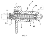
- hydraulic tensioner 1 includes mainly housing 2, hollow plunger 3 inserted slidably into bore 2a of housing 2, and spring 4 that pushes plunger 3 toward its projection bore 2a.
- a chamber 20 is formed in housing 2 by the inner wall of bore 2a and the inner wall of plunger 3. Open hole or aperture 31a is formed at the center of tip 31 of plunger 3 at the plunger upper end.
- a ball check valve 6 is provided on the bottom wall of the chamber inside housing 2. This ball check valve 6 allows fluid to flow into chamber 20 and blocks its reverse flow. Housing 2 has a passage 7 to connect chamber 20 to the external pressurized fluid source P.
- a pressure relief valve assembly 5 is provided on the side of tip 31 inside plunger 3. This pressure relief valve assembly 5 permits fluid to flow out from chamber 20 when the fluid pressure in chamber 20 exceeds a set maximum value.
- Air vent disc 10 is integrally assembled within pressure relief valve assembly 5. The force of spring 4 acts on plunger 3 via pressure relief valve 5 and air vent disc 10, and spring 4 causes plunger tip 31 to contact air vent disc 10.
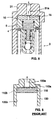
- FIG. 2 shows an enlargement of pressure relief valve assembly 5 and air vent disc 10.
- Pressure relief valve assembly 5 includes a valve housing 51 with open holes 51a, 51b on both of its ends.
- Plug member 52 is fixed in valve housing 51 and ball 53, that can contact seat 51c is formed in valve housing 51 and a valve spring 54 urges ball 53 onto seat 51c.
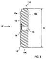
- air vent disc 10 is in the shape of a disc and is composed of first and second main surfaces 10a, 10b and outer periphery 10c. Curved radius 16 is formed on the peripheral edge of first main surface 10a. A chamfer with the same machining stock as said radius 16 can be formed in place of radius 16.
- Spiral groove 13 is formed on the first main surface 10a as a vent channel (see FIG. 4). As shown in FIG. 4, starting end 13a of groove 13 is tapered down and its tip is positioned on radius 16. Terminal end 13b of groove 13 is connected to countersunk hole 14 formed at the center. Through-hole 15, connecting to countersunk hole 14, is formed at the center of air vent disc 10.
- Outer diameter D (FIG. 3) of air vent disc 10 is slightly smaller than the hole diameter of plunger 3 and, as shown in FIG. 2, a clearance is formed between outer periphery 10c of air vent disc 10 and the inner wall of the plunger during assembly into plunger 3.
- second main surface 10b of air vent disc 10 is opposite valve housing 51 of pressure relief valve assembly 5 and these components are inserted into plunger 3 while air vent disc 10 and pressure relief valve assembly 5 are assembled integrally.
- First main surface 10a with groove 13 of air vent disc 10 is opposite plunger tip 31.
- Air vent disc 10 and pressure relief valve assembly 5 are integrally assembled inside the plunger, so that both can be assembled in one process (i.e., at one station of the assembly machine), thereby, the labor and assembly costs are reduced.
- Plunger 3 protrudes during operation of hydraulic tensioner 1 due to the combined force of spring 4 and the fluid pressure in chamber 20.
- the tip 31 of the plunger 3 contacts an associated chain (not shown) and applies tension to the chain, typically be bearing upon a tensioner arm or shoe (not shown).
- the inward force acting from the chain onto plunger 3 is balanced with the outward force due to spring 4 and the fluid pressure in chamber 20.
- a gap is formed between outer periphery 10c of air vent disc 10 and the inner periphery of plunger 3. Therefore, the mixed-in air in chamber 20 passes through an optional position on outer periphery 10c of air vent disc 10 and flows into first main surface 10a of air vent disc 10. At such a time, the mixed-in air flows from radius 16 into starting end 13a of groove 13, smoothly, because starting end 13a of groove 13 is located at radius 16 formed on the peripheral edge of first main surface 10a of air vent disc 10 and the mixed-in air exit outside of the tensioner from terminal end 13b of groove 13. Thereby, the flow of mixed-in air from air vent disc 10 is made smooth.
- the axial groove or notch that connects to radius 16 can be formed on outer periphery 10c of air vent disc 10.
- the air mixed in into chamber 20 during operation passes through the groove or notch on the outer periphery 10c of air vent disc 10 and the radius 16 or peripheral edge of the first main surface 10a of air vent disc 10 and flows into starting end 13a of groove 13.
- the mixed-in air is discharged together with fluid (hydraulic oil) via groove 13, terminal end 13b and open hole 31a at plunger tip 31.
- groove 13 as vent passage is in a spiral shape, but the shape of groove 13 is not limited to such a shape.
- Various circuitous paths are contemplated from its starting end to its terminal end.
- a vent device and a pressure relief valve assembly are integral with a plunger, so that the assembly can be made in one process, for reduction of labor and assembly cost. Furthermore, a gap is formed between the outer periphery of the vent device and the inner periphery of the plunger and a chamfer or radius is formed on the peripheral edge of the first main surface of the vent device and the starting end of the vent passage is located at the chamfer or radius, so that mixed-in air in the chamber can flow smoothly to the starting end of the vent passage, past the chamfer or radius, and thereby, flow-out of mixed-in air from the vent device is smooth.
Landscapes
- Engineering & Computer Science (AREA)
- General Engineering & Computer Science (AREA)
- Mechanical Engineering (AREA)
- Devices For Conveying Motion By Means Of Endless Flexible Members (AREA)
Applications Claiming Priority (2)
| Application Number | Priority Date | Filing Date | Title |
|---|---|---|---|
| JP11189959A JP2001021011A (ja) | 1999-07-05 | 1999-07-05 | 液圧テンショナ |
| JP18995999 | 1999-07-05 |
Publications (3)
| Publication Number | Publication Date |
|---|---|
| EP1067314A2 true EP1067314A2 (de) | 2001-01-10 |
| EP1067314A3 EP1067314A3 (de) | 2003-12-17 |
| EP1067314B1 EP1067314B1 (de) | 2006-04-12 |
Family
ID=16250064
Family Applications (1)
| Application Number | Title | Priority Date | Filing Date |
|---|---|---|---|
| EP00305562A Expired - Lifetime EP1067314B1 (de) | 1999-07-05 | 2000-07-03 | Hydraulischer Kettenspanner mit Entlüftungseinrichtung und Überdruckventil |
Country Status (4)
| Country | Link |
|---|---|
| US (1) | US6435993B1 (de) |
| EP (1) | EP1067314B1 (de) |
| JP (1) | JP2001021011A (de) |
| DE (1) | DE60027227T2 (de) |
Cited By (7)
| Publication number | Priority date | Publication date | Assignee | Title |
|---|---|---|---|---|
| EP1348887A3 (de) * | 2002-03-28 | 2005-02-02 | Honda Giken Kogyo Kabushiki Kaisha | Hydraulische Spannvorrichtung |
| DE102004040222A1 (de) * | 2004-08-19 | 2006-03-02 | Ina-Schaeffler Kg | Hydraulische Spannvorrichtung für einen Zugmitteltrieb |
| EP1602857A3 (de) * | 2004-05-31 | 2007-07-04 | Tsubakimoto Chain Co. | Hydraulische Spannvorrichtung |
| WO2007124780A1 (de) * | 2006-04-28 | 2007-11-08 | Iwis Motorsysteme Gmbh & Co. Kg | Kettenspanner mit deckelelement |
| WO2007149648A1 (en) | 2006-06-21 | 2007-12-27 | Borgwarner Inc | Check valve with spring retained ball |
| WO2009092491A2 (de) * | 2008-01-24 | 2009-07-30 | Schaeffler Kg | Überdruckventil mit hubbegrenzung |
| WO2012119632A1 (de) * | 2011-03-09 | 2012-09-13 | Iwis Motorsysteme Gmbh & Co. Kg | Spannvorrichtung mit mindestens zwei entlüftungselementen |
Families Citing this family (42)
| Publication number | Priority date | Publication date | Assignee | Title |
|---|---|---|---|---|
| JP3356762B2 (ja) * | 2000-10-26 | 2002-12-16 | 株式会社椿本チエイン | リリーフバルブ機構付きテンショナ |
| JP4014145B2 (ja) * | 2002-08-02 | 2007-11-28 | 本田技研工業株式会社 | 自動車用パワートレンのブリーザ装置 |
| US6945889B2 (en) * | 2002-10-04 | 2005-09-20 | Borgwarner Inc. | Hydraulic chain tensioner |
| DE102004048281A1 (de) * | 2004-10-05 | 2006-04-06 | Ina-Schaeffler Kg | Hydraulischer Spanner |
| JP3980023B2 (ja) * | 2004-10-26 | 2007-09-19 | 株式会社椿本チエイン | リリーフバルブ付き油圧式テンショナ |
| JP3962052B2 (ja) | 2004-11-02 | 2007-08-22 | 株式会社椿本チエイン | 油圧式テンショナ |
| JP3962054B2 (ja) * | 2004-11-22 | 2007-08-22 | 株式会社椿本チエイン | 脱気型油圧テンショナ |
| US20070034262A1 (en) * | 2005-08-09 | 2007-02-15 | Eric Cozens | Pressure relief valve |
| DE102005061444A1 (de) | 2005-12-22 | 2007-07-05 | GM Global Technology Operations, Inc., Detroit | Kettenspanneinrichtung für einen Verbrennungsmotor |
| JP4327191B2 (ja) * | 2006-10-12 | 2009-09-09 | 株式会社椿本チエイン | 脱気型油圧テンショナ |
| DE102007033600A1 (de) * | 2007-07-17 | 2009-01-22 | Schaeffler Kg | Hydraulisches Spannsystem mit integriertem Überdruckventil |
| US7549898B2 (en) * | 2007-09-26 | 2009-06-23 | Fci Americas Technology, Inc. | Waterproof electrical connector |
| JP2010091055A (ja) * | 2008-10-09 | 2010-04-22 | Ntn Corp | チェーンテンショナ |
| DE102008053930A1 (de) * | 2008-10-30 | 2010-05-06 | Schaeffler Kg | Überdruckventil |
| TWI385327B (zh) * | 2010-01-27 | 2013-02-11 | Kmc Chain Ind Co Ltd | 液壓張緊裝置 |
| DE102011006602A1 (de) * | 2011-03-31 | 2012-10-04 | Schaeffler Technologies Gmbh & Co. Kg | Zugmittelspanner mit einem Überdruckventil, das einen dichtenden Käfig aufweist sowie Zugmitteltrieb mit einem solchen Zugmittelspanner |
| DE102011079184A1 (de) * | 2011-07-14 | 2013-01-17 | Schaeffler Technologies AG & Co. KG | Überdruckventil in einem Spannsystem |
| DE102012216056A1 (de) | 2012-09-11 | 2014-03-13 | Schaeffler Technologies AG & Co. KG | Als Rückschlagventil ausgeführtes Überdruckventil |
| US10006524B2 (en) * | 2013-12-03 | 2018-06-26 | Borgwarner Inc. | Integrated pressure relief valve for hydraulic tensioner |
| DE102013225984B4 (de) * | 2013-12-16 | 2017-03-23 | Schaeffler Technologies AG & Co. KG | Hydraulische Spannvorrichtung für einen Zugmitteltrieb |
| WO2016069262A1 (en) * | 2014-10-29 | 2016-05-06 | Borgwarner Inc. | Valvular paths |
| CN107110309A (zh) * | 2014-10-29 | 2017-08-29 | 博格华纳公司 | 涡流通道 |
| KR20170102891A (ko) | 2014-12-29 | 2017-09-12 | 보르그워너 인코퍼레이티드 | 모듈식 유압 텐셔너용 무게 및 비용 최적화 캐리어 |
| JP6294851B2 (ja) * | 2015-04-03 | 2018-03-14 | 株式会社椿本チエイン | チェーンテンショナ及びリリーフバルブユニット |
| JP6564630B2 (ja) * | 2015-06-27 | 2019-08-21 | ボーグワーナー インコーポレーテッド | 一体型チェック・リリーフバルブ |
| JP6523844B2 (ja) * | 2015-07-18 | 2019-06-05 | ボーグワーナー インコーポレーテッド | 一体型チェック・リリーフバルブ |
| US10781892B2 (en) | 2015-07-31 | 2020-09-22 | Borgwarner Inc. | Press-fit check valve for a hydraulic tensioner reservoir with metered backflow |
| JP6374840B2 (ja) * | 2015-08-03 | 2018-08-15 | 株式会社椿本チエイン | テンショナ |
| JP6408975B2 (ja) * | 2015-11-10 | 2018-10-17 | 株式会社椿本チエイン | チェーンテンショナ |
| JP6408977B2 (ja) * | 2015-11-25 | 2018-10-17 | 株式会社椿本チエイン | テンショナ |
| DE102016207779B4 (de) * | 2016-05-04 | 2022-01-05 | Schaeffler Technologies AG & Co. KG | Spannvorrichtung für einen Kettentrieb |
| US10738861B2 (en) * | 2016-12-20 | 2020-08-11 | Borgwarner Inc. | Control of hydraulic tensioner tuning using hole size in piston nose |
| CN110023595A (zh) * | 2016-12-21 | 2019-07-16 | 博格华纳公司 | 用于液压张紧器的泄压阀上的过滤器结构 |
| JP2020503476A (ja) * | 2017-01-04 | 2020-01-30 | ボーグワーナー インコーポレーテッド | 油圧テンショナ用のチェックバルブアセンブリ構造 |
| DE102018114200A1 (de) | 2017-06-15 | 2018-12-20 | Borgwarner Inc. | Spanner mit Rückschlagventil mit steuerbarer Steifigkeit |
| CN110005770B (zh) * | 2017-12-22 | 2022-05-06 | 株式会社椿本链条 | 张紧装置 |
| EP3759377B1 (de) | 2018-02-26 | 2022-08-24 | Borgwarner Inc. | Variabler kraftspanner mit interner reservoirtechnologie-primärbohrung |
| JP7007582B2 (ja) * | 2018-03-12 | 2022-01-24 | 株式会社椿本チエイン | テンショナ |
| JP6982243B2 (ja) * | 2018-04-18 | 2021-12-17 | 株式会社椿本チエイン | テンショナ |
| CN108869670A (zh) * | 2018-06-15 | 2018-11-23 | 重庆长安汽车股份有限公司 | 一种正时链条张紧装置、发动机及汽车 |
| JP2020101279A (ja) * | 2018-12-21 | 2020-07-02 | ボーグワーナー インコーポレーテッド | 内部チェックバルブを含むピストンが備えられたテンショナ |
| JP7417032B2 (ja) * | 2019-06-11 | 2024-01-18 | 株式会社椿本チエイン | テンショナ |
Citations (2)
| Publication number | Priority date | Publication date | Assignee | Title |
|---|---|---|---|---|
| JPH07158703A (ja) | 1993-09-23 | 1995-06-20 | Borg Warner Automot Inc | 液圧チェーンテンショナ |
| JPH09119490A (ja) | 1995-08-18 | 1997-05-06 | Borg Warner Automot Inc | 液圧テンショナ |
Family Cites Families (6)
| Publication number | Priority date | Publication date | Assignee | Title |
|---|---|---|---|---|
| DE3639389A1 (de) * | 1986-11-18 | 1988-05-19 | Winkelhofer & Soehne Joh | Kettenspann- und -schmiervorrichtung |
| JP3752017B2 (ja) | 1996-05-10 | 2006-03-08 | ボルグワーナー・モールステック・ジャパン株式会社 | 油圧テンショナ |
| CN1092304C (zh) * | 1996-08-02 | 2002-10-09 | Ina滚动轴承谢夫勒无限责任公司 | 张紧装置 |
| US5707309A (en) | 1997-01-23 | 1998-01-13 | Borg-Warner Automotive, Inc. | Hydraulic tensioner with modular inlet check valve with pressure relief |
| US5993342A (en) * | 1997-03-26 | 1999-11-30 | Borg-Warner Automotive, Inc. | Hydraulic tensioner with force limiting tensioner spring |
| US6139454A (en) | 1998-09-21 | 2000-10-31 | Borgwarner Inc. | Hydraulic tensioner with plastic cap check valve or vent |
-
1999
- 1999-07-05 JP JP11189959A patent/JP2001021011A/ja active Pending
-
2000
- 2000-06-21 US US09/599,822 patent/US6435993B1/en not_active Expired - Lifetime
- 2000-07-03 EP EP00305562A patent/EP1067314B1/de not_active Expired - Lifetime
- 2000-07-03 DE DE60027227T patent/DE60027227T2/de not_active Expired - Lifetime
Patent Citations (2)
| Publication number | Priority date | Publication date | Assignee | Title |
|---|---|---|---|---|
| JPH07158703A (ja) | 1993-09-23 | 1995-06-20 | Borg Warner Automot Inc | 液圧チェーンテンショナ |
| JPH09119490A (ja) | 1995-08-18 | 1997-05-06 | Borg Warner Automot Inc | 液圧テンショナ |
Cited By (12)
| Publication number | Priority date | Publication date | Assignee | Title |
|---|---|---|---|---|
| EP1348887A3 (de) * | 2002-03-28 | 2005-02-02 | Honda Giken Kogyo Kabushiki Kaisha | Hydraulische Spannvorrichtung |
| US7070528B2 (en) | 2002-03-28 | 2006-07-04 | Honda Giken Kogyo Kabushiki Kaisha | Hydraulic tensioner lifter |
| EP1602857A3 (de) * | 2004-05-31 | 2007-07-04 | Tsubakimoto Chain Co. | Hydraulische Spannvorrichtung |
| DE102004040222A1 (de) * | 2004-08-19 | 2006-03-02 | Ina-Schaeffler Kg | Hydraulische Spannvorrichtung für einen Zugmitteltrieb |
| WO2006021271A1 (de) * | 2004-08-19 | 2006-03-02 | Schaeffler Kg | Hydraulische spannvorrichtung für einen zugmitteltrieb |
| US7775924B2 (en) | 2004-08-19 | 2010-08-17 | Schaeffler Kg | Hydraulic tensioning device for a traction mechanism drive |
| WO2007124780A1 (de) * | 2006-04-28 | 2007-11-08 | Iwis Motorsysteme Gmbh & Co. Kg | Kettenspanner mit deckelelement |
| WO2007149648A1 (en) | 2006-06-21 | 2007-12-27 | Borgwarner Inc | Check valve with spring retained ball |
| WO2009092491A2 (de) * | 2008-01-24 | 2009-07-30 | Schaeffler Kg | Überdruckventil mit hubbegrenzung |
| WO2009092491A3 (de) * | 2008-01-24 | 2009-10-01 | Schaeffler Kg | Überdruckventil mit hubbegrenzung |
| WO2012119632A1 (de) * | 2011-03-09 | 2012-09-13 | Iwis Motorsysteme Gmbh & Co. Kg | Spannvorrichtung mit mindestens zwei entlüftungselementen |
| US8974333B2 (en) | 2011-03-09 | 2015-03-10 | Iwis Motorsysteme Gmbh & Co., Kg | Tensioning device with at least two vent elements |
Also Published As
| Publication number | Publication date |
|---|---|
| EP1067314A3 (de) | 2003-12-17 |
| EP1067314B1 (de) | 2006-04-12 |
| DE60027227T2 (de) | 2006-08-31 |
| JP2001021011A (ja) | 2001-01-26 |
| DE60027227D1 (de) | 2006-05-24 |
| US6435993B1 (en) | 2002-08-20 |
Similar Documents
| Publication | Publication Date | Title |
|---|---|---|
| US6435993B1 (en) | Hydraulic chain tensioner with vent device and pressure relief valve | |
| US6352487B1 (en) | Hydraulic chain tensioner with directional vent device | |
| US5707309A (en) | Hydraulic tensioner with modular inlet check valve with pressure relief | |
| US7174799B2 (en) | Hydraulic tensioner | |
| JP3703588B2 (ja) | 液圧テンショナ | |
| US7608004B2 (en) | Deairing type hydraulic tensioner | |
| JP3926182B2 (ja) | ラチェット式油圧テンショナ | |
| US6899126B2 (en) | Check valve and valve arrangement comprising such a check valve | |
| KR100531528B1 (ko) | 유압식 텐셔너 리프터 | |
| US7429167B2 (en) | Scroll machine having a discharge valve assembly | |
| US8038420B2 (en) | Variable displacement vane pump | |
| EP1101975A3 (de) | Druckbegrenzungsventil und Scheibe mit zwei Auslasswegen für hydraulische Spannvorrichtung | |
| US10900545B2 (en) | Chain tensioner | |
| EP0989332A2 (de) | Hydraulischer Spanner mit interner Kolbenfeder und schneller Entlüftung | |
| US11143100B2 (en) | Tensioner | |
| JP3441289B2 (ja) | 油圧回路用弁構造 | |
| WO2020032094A1 (ja) | チェーンテンショナ | |
| US6116272A (en) | Debris resistant oil pressure relief valve | |
| JP2007032711A (ja) | 油圧式オートテンショナ | |
| JP2007032678A (ja) | 油圧式オートテンショナ | |
| KR20190121684A (ko) | 텐셔너 | |
| US6416298B1 (en) | Radial piston pump | |
| WO2020184322A1 (ja) | チェーンテンショナ | |
| JP3058815B2 (ja) | 油圧式オートテンショナ | |
| JPH09203447A (ja) | 油圧式オートテンショナ |
Legal Events
| Date | Code | Title | Description |
|---|---|---|---|
| PUAI | Public reference made under article 153(3) epc to a published international application that has entered the european phase |
Free format text: ORIGINAL CODE: 0009012 |
|
| AK | Designated contracting states |
Kind code of ref document: A2 Designated state(s): AT BE CH CY DE DK ES FI FR GB GR IE IT LI LU MC NL PT SE |
|
| AX | Request for extension of the european patent |
Free format text: AL;LT;LV;MK;RO;SI |
|
| RAP1 | Party data changed (applicant data changed or rights of an application transferred) |
Owner name: BORGWARNER MORSE TEC JAPAN K.K. |
|
| PUAL | Search report despatched |
Free format text: ORIGINAL CODE: 0009013 |
|
| AK | Designated contracting states |
Kind code of ref document: A3 Designated state(s): AT BE CH CY DE DK ES FI FR GB GR IE IT LI LU MC NL PT SE |
|
| AX | Request for extension of the european patent |
Extension state: AL LT LV MK RO SI |
|
| 17P | Request for examination filed |
Effective date: 20040212 |
|
| AKX | Designation fees paid |
Designated state(s): DE FR IT |
|
| 17Q | First examination report despatched |
Effective date: 20040906 |
|
| GRAP | Despatch of communication of intention to grant a patent |
Free format text: ORIGINAL CODE: EPIDOSNIGR1 |
|
| RAP1 | Party data changed (applicant data changed or rights of an application transferred) |
Owner name: BORGWARNER MORSE TEC JAPAN K.K. |
|
| GRAS | Grant fee paid |
Free format text: ORIGINAL CODE: EPIDOSNIGR3 |
|
| GRAA | (expected) grant |
Free format text: ORIGINAL CODE: 0009210 |
|
| AK | Designated contracting states |
Kind code of ref document: B1 Designated state(s): DE FR IT |
|
| REF | Corresponds to: |
Ref document number: 60027227 Country of ref document: DE Date of ref document: 20060524 Kind code of ref document: P |
|
| ET | Fr: translation filed | ||
| PLBE | No opposition filed within time limit |
Free format text: ORIGINAL CODE: 0009261 |
|
| STAA | Information on the status of an ep patent application or granted ep patent |
Free format text: STATUS: NO OPPOSITION FILED WITHIN TIME LIMIT |
|
| 26N | No opposition filed |
Effective date: 20070115 |
|
| PGFP | Annual fee paid to national office [announced via postgrant information from national office to epo] |
Ref country code: FR Payment date: 20080707 Year of fee payment: 9 Ref country code: IT Payment date: 20080718 Year of fee payment: 9 |
|
| REG | Reference to a national code |
Ref country code: FR Ref legal event code: ST Effective date: 20100331 |
|
| PG25 | Lapsed in a contracting state [announced via postgrant information from national office to epo] |
Ref country code: FR Free format text: LAPSE BECAUSE OF NON-PAYMENT OF DUE FEES Effective date: 20090731 |
|
| PG25 | Lapsed in a contracting state [announced via postgrant information from national office to epo] |
Ref country code: IT Free format text: LAPSE BECAUSE OF NON-PAYMENT OF DUE FEES Effective date: 20090703 |
|
| PGFP | Annual fee paid to national office [announced via postgrant information from national office to epo] |
Ref country code: DE Payment date: 20190617 Year of fee payment: 20 |
|
| REG | Reference to a national code |
Ref country code: DE Ref legal event code: R071 Ref document number: 60027227 Country of ref document: DE |