EP1066930A2 - Werkzeug mit handbetriebener Spindelverriegelung - Google Patents
Werkzeug mit handbetriebener Spindelverriegelung Download PDFInfo
- Publication number
- EP1066930A2 EP1066930A2 EP00305654A EP00305654A EP1066930A2 EP 1066930 A2 EP1066930 A2 EP 1066930A2 EP 00305654 A EP00305654 A EP 00305654A EP 00305654 A EP00305654 A EP 00305654A EP 1066930 A2 EP1066930 A2 EP 1066930A2
- Authority
- EP
- European Patent Office
- Prior art keywords
- power tool
- cam
- cam member
- spindle
- engaging
- Prior art date
- Legal status (The legal status is an assumption and is not a legal conclusion. Google has not performed a legal analysis and makes no representation as to the accuracy of the status listed.)
- Granted
Links
Images

Classifications
-
- B—PERFORMING OPERATIONS; TRANSPORTING
- B25—HAND TOOLS; PORTABLE POWER-DRIVEN TOOLS; MANIPULATORS
- B25B—TOOLS OR BENCH DEVICES NOT OTHERWISE PROVIDED FOR, FOR FASTENING, CONNECTING, DISENGAGING OR HOLDING
- B25B21/00—Portable power-driven screw or nut setting or loosening tools; Attachments for drilling apparatus serving the same purpose
-
- B—PERFORMING OPERATIONS; TRANSPORTING
- B25—HAND TOOLS; PORTABLE POWER-DRIVEN TOOLS; MANIPULATORS
- B25F—COMBINATION OR MULTI-PURPOSE TOOLS NOT OTHERWISE PROVIDED FOR; DETAILS OR COMPONENTS OF PORTABLE POWER-DRIVEN TOOLS NOT PARTICULARLY RELATED TO THE OPERATIONS PERFORMED AND NOT OTHERWISE PROVIDED FOR
- B25F5/00—Details or components of portable power-driven tools not particularly related to the operations performed and not otherwise provided for
- B25F5/001—Gearings, speed selectors, clutches or the like specially adapted for rotary tools
-
- Y—GENERAL TAGGING OF NEW TECHNOLOGICAL DEVELOPMENTS; GENERAL TAGGING OF CROSS-SECTIONAL TECHNOLOGIES SPANNING OVER SEVERAL SECTIONS OF THE IPC; TECHNICAL SUBJECTS COVERED BY FORMER USPC CROSS-REFERENCE ART COLLECTIONS [XRACs] AND DIGESTS
- Y10—TECHNICAL SUBJECTS COVERED BY FORMER USPC
- Y10T—TECHNICAL SUBJECTS COVERED BY FORMER US CLASSIFICATION
- Y10T279/00—Chucks or sockets
- Y10T279/34—Accessory or component
- Y10T279/3431—Chuck key
Definitions
- the present invention relates to power tools and, more particularly, to power tools such as power screwdrivers with manual spindle locks.
- Varying torque or force is applied to a fastener as the fastener, such as a screw or bolt, is advanced into or removed from an anchoring position.
- a fastener such as a screw or bolt
- large forces are required to set the screw during installation or to initially break loose the screw during removal.
- difficulties are encountered in generating these large forces.
- the underlying limitation of these tools is the motor horsepower. This problem is further aggravated in battery operated tools. In battery operated tools, to have sufficient electrical capacity from the battery to operate a high torque power tool, a large heavy size tool is required. Thus, lightweight self-contained battery operated tools are limited in the amount of torque which can be produced.
- the prior art teaches conventional screwdrivers being utilized with power tools to deliver the high torque. Also, elaborate drive trains may be associated with the power tool to deliver the increased torque. However, this lowers the drive speed. Further, different types of shaft locks have been provided. The shaft locks provide the powered screwdriver with the high torque feature of a manual screwdriver when required. Thus, it is desirable to have a power tool with a manual spindle lock to be utilized in high torque situations.
- the present invention provides a simple cost-effective design to provide a spindle lock with a power tool such as a compact power screwdriver.
- a power tool with a manual spindle lock comprising:
- a spindle lock for a power tool comprising:
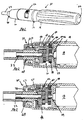
- a power tool such as a power screwdriver is illustrated and designated with the reference numeral 10.
- the power tool 10 includes a housing 12 with a motor housing portion 14 and a gear housing portion 16.
- a motor 18 is housed within the motor housing portion 14 and a gear train 20 is housed within the gear housing portion 16.
- An output spindle 22 is coupled with the gear train 20 and is driven by the motor 14.
- a battery 24 is electrically coupled with the motor 18 and is positioned within the motor housing 14.
- a spindle locking device 30 is coupled with the housing as will be described herein.
- the power tool 10 includes an activation switch 32 such as a toggle switch for energizing and de-energizing the motor.
- the switch 32 is connected between the battery 24 and the motor 18.
- the pinion gear 34 at the end of the motor shaft 36 is rotated.
- the pinion gear 34 rotates a first set of planet gears 38 which, in turn, rotate sun gear 40.
- Sun gear 40 in turn rotates a second set of planetary gears 42 which, in turn, rotate the output carrier gear 44.
- the output carrier gear 44 is coupled with the output shaft 22.
- the gear housing portion 16 includes teeth 46 peripherally positioned on the inner surface of the gear housing portion 16. The teeth 46 mesh with the first and second set of planet gears 38 and 42.
- the spindle lock 30 engages and disengages the output gear 44 which locks the gear train 20 to enable the power tool to be used manually.
- the spindle lock 30 includes a first member 50 and a second member 52.
- the first member 50 includes an annular or ring member 54 with a plurality of projecting cantilevered fingers 56.
- the annular member 54 includes outer circumferential teeth 57 to couple with teeth or splines 46 on the inner peripheral surface of the gear housing portion 16.
- the annular member 54 has internal teeth 60 which mesh with the teeth 62 of the output carrier gear 44.
- the annular member 52 is open at the tooth end and has a radial wall 64 partially closing the other end of the annular member.
- the radial wall 64 has a central opening 66 which is positioned around the spindle housing portion 68 of the gear housing portion 16.
- the projecting fingers 56 extend from the radial wall 64.
- the fingers 56 include cam elements 70.
- the cam elements 70 are illustrated as projecting pins.
- the projecting fingers 56 with the cam elements 70 are generally unitarily formed with the annular member 54.
- the first member 50 may be formed from a plastic or metallic material.
- the second member 52 is positioned around the projecting members 56 and the spindle housing 68.
- the second member 52 has a ring portion 72 and an end wall 74 extending radially inward from the ring 72.
- the radial wall 74 has a central opening 76 which is positioned around the spindle housing 68.
- a clip ring or washer 78 maintains the second member 52 onto the gear housing portion 16.
- the ring 72 includes an interior peripheral surface 80.
- the interior peripheral surface 80 includes a pair of parallel ribs 82, 84 which define a cam slot 86.
- the ribs 82 and 84 while parallel to one another, define a helical path such that the ribs 82 and 84 move away from the radial end wall 74 along their peripheral path. Accordingly, the cam slot 86 likewise moves away from the radial wall 74 along a helical path.
- Cam elements 70 fit within the cam slot 86.
- the cam elements 70 are moved along the helical path away from the radial wall 74.
- the cam elements 70 move axially.
- the extending fingers 56, as well as the annular member 54 move axially.
- the teeth 60 engage with the teeth 62 of the output carrier gear 48. This is best seen in Figures 2 and 3.
- the drive train 20 is locked. This is due to the fact that the outer teeth 56 of the annular member 54, which slide in teeth 46, are fixed against rotation in the gear housing portion 16.
- the power tool may be used in a manual position.
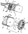
- FIG. 6 a second embodiment of the present invention is shown.
- a spindle lock 30' is illustrated.
- the elements which are the same as those previously disclosed are identified with the same reference numerals.
- the difference between the above described spindle lock and the spindle lock of Figure 6 is that the cam elements 70 are partial thread members 70' which mate with partial thread elements 82' of the second member 52.
- the threads 70' move along a helical path towards and away from the radial wall 74 which, in turn, axially moves the annular member 54 engaging and disengaging annular member teeth 60 with output gear 62.
- the spindle lock 30' operates similarly to the spindle lock 30 described above.
- FIG. 7 a third embodiment of the present invention is shown.
- a spindle lock 30'' is illustrated.
- the elements which are the same as those previously disclosed are identified with the same reference numerals.
- the difference between the above-described spindle lock and the spindle lock of Figure 7 is that the first member does not include a large annular member with outer circumferential teeth which would couple with teeth 46 of the inner periphery surface of the gear housing portion 16.
- the first member 50' includes projecting members 56 with cams 70 which are pins.
- the annular member 54'' is a circular ring. The end surface 57'' would frictionally engage the gear carrier 44 like that illustrated in Figure 3.
- the frictional contact between the end face 57'' and the output carrier 44 would prohibit rotation of the output carrier as well as the gear train to manually lock the gear train.
- the surface 57'' may include a plurality of recesses (shown in phantom) which would receive projections from the output carrier 44 (not shown) to effectively connect the ring 54'' with the output carrier 44.
Landscapes
- Engineering & Computer Science (AREA)
- Mechanical Engineering (AREA)
- Details Of Spanners, Wrenches, And Screw Drivers And Accessories (AREA)
- Transmission Devices (AREA)
- Preventing Unauthorised Actuation Of Valves (AREA)
- Jigs For Machine Tools (AREA)
- Portable Power Tools In General (AREA)
- Constituent Portions Of Griding Lathes, Driving, Sensing And Control (AREA)
- Automatic Tool Replacement In Machine Tools (AREA)
- Drilling And Boring (AREA)
Applications Claiming Priority (2)
| Application Number | Priority Date | Filing Date | Title |
|---|---|---|---|
| US09/348,895 US6273200B1 (en) | 1999-07-07 | 1999-07-07 | Screwdriver with manuel spindel lock |
| US348895 | 1999-07-07 |
Publications (3)
| Publication Number | Publication Date |
|---|---|
| EP1066930A2 true EP1066930A2 (de) | 2001-01-10 |
| EP1066930A3 EP1066930A3 (de) | 2002-02-06 |
| EP1066930B1 EP1066930B1 (de) | 2004-03-17 |
Family
ID=23370029
Family Applications (1)
| Application Number | Title | Priority Date | Filing Date |
|---|---|---|---|
| EP00305654A Expired - Lifetime EP1066930B1 (de) | 1999-07-07 | 2000-07-05 | Werkzeug mit handbetriebener Spindelverriegelung |
Country Status (9)
| Country | Link |
|---|---|
| US (1) | US6273200B1 (de) |
| EP (1) | EP1066930B1 (de) |
| CN (1) | CN1168579C (de) |
| AT (1) | ATE261796T1 (de) |
| CA (1) | CA2313160C (de) |
| DE (1) | DE60008971T2 (de) |
| DK (1) | DK1066930T3 (de) |
| ES (1) | ES2214225T3 (de) |
| HK (1) | HK1030757A1 (de) |
Cited By (10)
| Publication number | Priority date | Publication date | Assignee | Title |
|---|---|---|---|---|
| GB2380439A (en) * | 2001-08-24 | 2003-04-09 | Bosch Gmbh Robert | A holding device for an electric tool machine. |
| DE10243920B3 (de) * | 2002-09-20 | 2004-11-04 | Siemens Ag | Vorrichtung zum lösbaren Befestigen eines Motors an einem Förderer |
| US7134364B2 (en) | 2003-09-29 | 2006-11-14 | Robert Bosch Gmbh | Battery-driven screwdriver |
| US7197961B2 (en) | 2003-09-29 | 2007-04-03 | Robert Bosch Gmbh | Battery-driven screwdriver with a two-part motor housing and a separate, flanged gear unit |
| US7469753B2 (en) | 2005-06-01 | 2008-12-30 | Milwaukee Electric Tool Corporation | Power tool, drive assembly, and method of operating the same |
| US7498526B2 (en) | 2004-08-09 | 2009-03-03 | Robert Bosch Gmbh | Cordless screwdriver |
| US7546785B2 (en) | 2004-08-09 | 2009-06-16 | Robert Bosch Gmbh | Battery-operated screwdriver |
| WO2009021718A3 (de) * | 2007-08-14 | 2009-08-13 | Wisap Gmbh | Vorrichtung zum antrieb von instrumenten und werkzeugen und deren verwendung |
| DE202004021818U1 (de) | 2004-08-09 | 2011-05-26 | Robert Bosch GmbH, 70469 | Akkuschrauber |
| EP3005963A1 (de) | 2014-10-08 | 2016-04-13 | Medartis Holding AG | Elektrische werkzeugmaschine, insbesondere elektrischer schraubendreher für die verwendung in der chirurgie |
Families Citing this family (39)
| Publication number | Priority date | Publication date | Assignee | Title |
|---|---|---|---|---|
| CN1234984C (zh) | 2000-03-14 | 2006-01-04 | 株式会社基茨 | 电动促动器及其固定构造 |
| US6702090B2 (en) | 2001-03-14 | 2004-03-09 | Milwaukee Electric Tool Corporation | Power tool and spindle lock system |
| US6776069B2 (en) | 2001-06-25 | 2004-08-17 | Toolovation, Llc | Battery powered screwdriver and screw starting device |
| US7063201B2 (en) * | 2001-11-27 | 2006-06-20 | Milwaukee Electric Tool Corporation | Power tool and spindle lock system |
| US6640674B1 (en) * | 2002-05-21 | 2003-11-04 | Pilling Weck Incorporated | Screwdriver having a variable torque-limiting in-line drive |
| US6675910B1 (en) * | 2003-06-19 | 2004-01-13 | Wu-Chang Lin | Structure of hand tool |
| DE10345135A1 (de) | 2003-09-29 | 2005-04-21 | Bosch Gmbh Robert | Akkuschrauber |
| CA2471616C (en) * | 2004-06-21 | 2009-12-22 | Dan Provost | Torque tool |
| US7216569B2 (en) * | 2005-03-10 | 2007-05-15 | Custom Spine, Inc. | Screwdriver handle |
| US7727047B2 (en) * | 2005-05-04 | 2010-06-01 | Julian Edward Lopez | Toy and method of toy operation |
| TW200738406A (en) * | 2006-04-11 | 2007-10-16 | Hou-Fei Hu | Ratchet driver with several rotary speeds |
| US7513845B2 (en) * | 2006-08-01 | 2009-04-07 | Eastway Fair Company Limited | Variable speed transmission for a power tool |
| US8303449B2 (en) * | 2006-08-01 | 2012-11-06 | Techtronic Power Tools Technology Limited | Automatic transmission for a power tool |
| US8057134B2 (en) | 2007-06-26 | 2011-11-15 | Techtronic Power Tools Technology Limited | Chuck assembly |
| US8075229B2 (en) * | 2007-06-26 | 2011-12-13 | Techtronic Power Tools Technology Limited | Multi-speed drill and chuck assembly |
| US7735575B2 (en) | 2007-11-21 | 2010-06-15 | Black & Decker Inc. | Hammer drill with hard hammer support structure |
| US7798245B2 (en) | 2007-11-21 | 2010-09-21 | Black & Decker Inc. | Multi-mode drill with an electronic switching arrangement |
| US7854274B2 (en) | 2007-11-21 | 2010-12-21 | Black & Decker Inc. | Multi-mode drill and transmission sub-assembly including a gear case cover supporting biasing |
| US7717191B2 (en) | 2007-11-21 | 2010-05-18 | Black & Decker Inc. | Multi-mode hammer drill with shift lock |
| US7762349B2 (en) | 2007-11-21 | 2010-07-27 | Black & Decker Inc. | Multi-speed drill and transmission with low gear only clutch |
| US7770660B2 (en) | 2007-11-21 | 2010-08-10 | Black & Decker Inc. | Mid-handle drill construction and assembly process |
| US7717192B2 (en) | 2007-11-21 | 2010-05-18 | Black & Decker Inc. | Multi-mode drill with mode collar |
| JP5117258B2 (ja) * | 2008-04-01 | 2013-01-16 | 株式会社マキタ | 自動変速式動力工具 |
| JP4961418B2 (ja) * | 2008-12-26 | 2012-06-27 | オムロン株式会社 | 電動工具 |
| US8011444B2 (en) * | 2009-04-03 | 2011-09-06 | Ingersoll Rand Company | Spindle locking assembly |
| DK177641B1 (en) * | 2010-04-29 | 2014-01-20 | Hilti Ag | A power tool |
| DE102011005553A1 (de) * | 2010-10-15 | 2012-04-19 | Robert Bosch Gmbh | Handgeführtes Elektrowerkzeug mit einer Spindellockvorrichtung |
| US20130072341A1 (en) * | 2011-09-15 | 2013-03-21 | Top Gearbox Industry Co., Ltd. | Multi-speed gear system for power tool |
| EP2888081B1 (de) * | 2012-08-27 | 2020-11-25 | Ingersoll-Rand Industrial U.S., Inc. | Konstruktion eines elektrowerkzeuggehäuses |
| US9550283B2 (en) | 2013-01-24 | 2017-01-24 | Ingersoll-Rand Company | Power tool with spindle lock |
| CN104708605B (zh) * | 2015-01-27 | 2017-01-18 | 宁波汉浦工具有限公司 | 带自锁装置的电动工具 |
| US10166668B2 (en) | 2015-11-19 | 2019-01-01 | Black & Decker Inc. | Power driven screwdriver |
| US10874442B2 (en) | 2015-12-23 | 2020-12-29 | Power T Handle, Llc | Multi-mode torque drivers employing inner surfaces compatible with pedicle screw guide wires, and related systems and methods |
| US10349984B2 (en) | 2015-12-23 | 2019-07-16 | Power T Handle, Llc | Multi-mode torque drivers employing anti-backdrive units for managing pedicle screw attachments with vertebrae, and related systems and methods |
| US10220493B2 (en) | 2016-09-06 | 2019-03-05 | Ingersoll-Rand Company | Spindle lock mechanism for pneumatic right-angle impact tool |
| CN115068028A (zh) * | 2016-11-10 | 2022-09-20 | 天津瑞奇外科器械股份有限公司 | 具有互锁功能的外科手术器械 |
| USD884889S1 (en) | 2018-12-18 | 2020-05-19 | Kevin S. CAHILL | Cannulated pedicle screw torque driver |
| CN111629864B (zh) * | 2019-03-14 | 2022-03-18 | 南京德朔实业有限公司 | 电动螺丝批 |
| US11511402B2 (en) | 2019-03-26 | 2022-11-29 | Black & Decker Inc. | Screwdriver and tool holder |
Citations (4)
| Publication number | Priority date | Publication date | Assignee | Title |
|---|---|---|---|---|
| DE4128651A1 (de) * | 1991-08-29 | 1993-03-04 | Gardena Kress & Kastner Gmbh | Elektroschrauber |
| EP0691180A2 (de) * | 1994-07-08 | 1996-01-10 | Metabowerke GmbH & Co. | Arretiervorrichtung für die Antriebsspindel von Handwerkzeugmaschinen |
| EP0706861A1 (de) * | 1993-03-05 | 1996-04-17 | Black & Decker Inc. | Motorgetriebens Gerät und Mechanismus dafür |
| US5704257A (en) * | 1994-11-17 | 1998-01-06 | Andreas Stihl | Securing mechanism for securing a drive shaft of a rotating tool member of a working tool |
Family Cites Families (31)
| Publication number | Priority date | Publication date | Assignee | Title |
|---|---|---|---|---|
| US2341529A (en) | 1940-04-23 | 1944-02-15 | Casco Products Corp | Chuck construction |
| US2436540A (en) | 1944-08-31 | 1948-02-24 | Casco Products Corp | Hand-held power tool |
| US2575903A (en) | 1949-01-25 | 1951-11-20 | Casco Products Corp | Power tool chuck |
| US2857997A (en) * | 1956-06-15 | 1958-10-28 | Clinton L Graybill | Power driven tool chuck |
| US2872197A (en) | 1957-09-10 | 1959-02-03 | Singer Mfg Co | Portable tools with selective means for locking spindle |
| DE1078958B (de) | 1958-04-24 | 1960-03-31 | Hanns Fickert | Elektroschraubenzieher |
| US2979089A (en) | 1958-04-24 | 1961-04-11 | Hanns Fickert | Portable battery-energized screw driver |
| US3021723A (en) | 1958-09-10 | 1962-02-20 | Diehl Mfg Co | Spindle locking means for portable tools |
| DE1478828A1 (de) * | 1964-10-24 | 1969-03-06 | Bosch Gmbh Robert | Motorisch angetriebenes Schraubgeraet |
| US3802518A (en) * | 1972-03-09 | 1974-04-09 | J Albert | Ratchet implement |
| US3872951A (en) | 1973-11-06 | 1975-03-25 | Black & Decker Mfg Co | Spindle locking mechanism for rotary power device |
| US3958469A (en) | 1975-10-14 | 1976-05-25 | Emerson Electric Co. | Torque wrench |
| US4159050A (en) | 1977-06-15 | 1979-06-26 | Black & Decker Inc. | Combination power tool |
| US4323324A (en) | 1979-04-18 | 1982-04-06 | Alfred F. Eberhardt | Chuck brake |
| US4249435A (en) | 1979-07-30 | 1981-02-10 | Smith William J | Workpiece turning hand tool with torque control |
| US4400995A (en) | 1981-09-23 | 1983-08-30 | Milwaukee Electric Tool Corporation | Spindle lock with impacting capability |
| US4448098A (en) * | 1982-03-10 | 1984-05-15 | Katsuyuki Totsu | Electrically driven screw-driver |
| DE3273401D1 (en) | 1982-03-11 | 1986-10-30 | Katsuyuki Totsu | An electrically driven screw-driver |
| US4804048A (en) | 1983-02-04 | 1989-02-14 | Skil Corporation | Hand-held tool with shaft lock |
| FR2598110B2 (fr) * | 1985-10-24 | 1989-11-03 | Black & Decker Inc | Tournevis motorise perfectionne |
| DE3636301A1 (de) | 1986-10-24 | 1988-04-28 | Steinel Gmbh & Co Kg | Handwerkszeug |
| US5016501B1 (en) | 1988-07-29 | 1997-07-15 | Sb Power Tool Co | Automatic shaft lock |
| US4878405A (en) | 1988-11-21 | 1989-11-07 | Ryobi Motor Products Corp. | Collet lock for power tool |
| DE8902467U1 (de) | 1989-03-02 | 1989-07-27 | Taiwan Silver Star Industrial Co., Ltd., Shen Kang Hsiang, Taichung, Tw | |
| US5025903A (en) * | 1990-01-09 | 1991-06-25 | Black & Decker Inc. | Dual mode rotary power tool with adjustable output torque |
| US5282510A (en) * | 1990-12-01 | 1994-02-01 | Hilti Aktiengesellschaft | Drilling and chipping tool |
| US5251706A (en) | 1992-12-03 | 1993-10-12 | Jack Evans | Ratchet drive tool with manual and non-manual power actuation |
| DE4342464A1 (de) | 1993-12-13 | 1995-06-14 | Joerg R Bauer | Schraubenschlüssel zum Fest- oder Losdrehen einer Schraube oder Mutter |
| US5496139A (en) | 1994-09-19 | 1996-03-05 | Snap-On Incorporated | Collet lock arrangement for power tool |
| SE503889C2 (sv) | 1994-10-31 | 1996-09-23 | Atlas Copco Tools Ab | Reverserbar mutterdragare |
| DE19608499C2 (de) | 1996-03-05 | 2000-05-25 | Regitar Power Tools Co | Automatische Verriegelungsvorrichtung zum automatischen Verriegeln der Abtriebswelle eines elektrischen Handwerkzeugs |
-
1999
- 1999-07-07 US US09/348,895 patent/US6273200B1/en not_active Expired - Lifetime
-
2000
- 2000-06-29 CA CA002313160A patent/CA2313160C/en not_active Expired - Fee Related
- 2000-07-05 ES ES00305654T patent/ES2214225T3/es not_active Expired - Lifetime
- 2000-07-05 EP EP00305654A patent/EP1066930B1/de not_active Expired - Lifetime
- 2000-07-05 AT AT00305654T patent/ATE261796T1/de not_active IP Right Cessation
- 2000-07-05 DK DK00305654T patent/DK1066930T3/da active
- 2000-07-05 DE DE60008971T patent/DE60008971T2/de not_active Expired - Lifetime
- 2000-07-07 CN CNB001204343A patent/CN1168579C/zh not_active Expired - Fee Related
-
2001
- 2001-03-09 HK HK01101692A patent/HK1030757A1/xx not_active IP Right Cessation
Patent Citations (4)
| Publication number | Priority date | Publication date | Assignee | Title |
|---|---|---|---|---|
| DE4128651A1 (de) * | 1991-08-29 | 1993-03-04 | Gardena Kress & Kastner Gmbh | Elektroschrauber |
| EP0706861A1 (de) * | 1993-03-05 | 1996-04-17 | Black & Decker Inc. | Motorgetriebens Gerät und Mechanismus dafür |
| EP0691180A2 (de) * | 1994-07-08 | 1996-01-10 | Metabowerke GmbH & Co. | Arretiervorrichtung für die Antriebsspindel von Handwerkzeugmaschinen |
| US5704257A (en) * | 1994-11-17 | 1998-01-06 | Andreas Stihl | Securing mechanism for securing a drive shaft of a rotating tool member of a working tool |
Cited By (15)
| Publication number | Priority date | Publication date | Assignee | Title |
|---|---|---|---|---|
| GB2380439B (en) * | 2001-08-24 | 2003-10-01 | Bosch Gmbh Robert | Electric tool machine having a plurality of functional modules accomodated in separate casings |
| US6862952B2 (en) | 2001-08-24 | 2005-03-08 | Robert Bosch Gmbh | Electric machining tool with a plurality of functional components in separate housings |
| GB2380439A (en) * | 2001-08-24 | 2003-04-09 | Bosch Gmbh Robert | A holding device for an electric tool machine. |
| DE10243920B3 (de) * | 2002-09-20 | 2004-11-04 | Siemens Ag | Vorrichtung zum lösbaren Befestigen eines Motors an einem Förderer |
| US7134364B2 (en) | 2003-09-29 | 2006-11-14 | Robert Bosch Gmbh | Battery-driven screwdriver |
| US7197961B2 (en) | 2003-09-29 | 2007-04-03 | Robert Bosch Gmbh | Battery-driven screwdriver with a two-part motor housing and a separate, flanged gear unit |
| US7723953B2 (en) | 2004-08-09 | 2010-05-25 | Robert Bosch Gmbh | Battery-operated screwdriver and charger shell therefor |
| US7498526B2 (en) | 2004-08-09 | 2009-03-03 | Robert Bosch Gmbh | Cordless screwdriver |
| US7546785B2 (en) | 2004-08-09 | 2009-06-16 | Robert Bosch Gmbh | Battery-operated screwdriver |
| DE202004021818U1 (de) | 2004-08-09 | 2011-05-26 | Robert Bosch GmbH, 70469 | Akkuschrauber |
| US7936148B2 (en) | 2004-08-09 | 2011-05-03 | Robert Bosch Gmbh | Battery-operated screwdriver and charger shell therefor |
| US7469753B2 (en) | 2005-06-01 | 2008-12-30 | Milwaukee Electric Tool Corporation | Power tool, drive assembly, and method of operating the same |
| US7658239B2 (en) | 2005-06-01 | 2010-02-09 | Milwaukee Electric Tool Corporation | Power tool, drive assembly, and method of operating the same |
| WO2009021718A3 (de) * | 2007-08-14 | 2009-08-13 | Wisap Gmbh | Vorrichtung zum antrieb von instrumenten und werkzeugen und deren verwendung |
| EP3005963A1 (de) | 2014-10-08 | 2016-04-13 | Medartis Holding AG | Elektrische werkzeugmaschine, insbesondere elektrischer schraubendreher für die verwendung in der chirurgie |
Also Published As
| Publication number | Publication date |
|---|---|
| ATE261796T1 (de) | 2004-04-15 |
| EP1066930B1 (de) | 2004-03-17 |
| CN1168579C (zh) | 2004-09-29 |
| HK1030757A1 (en) | 2001-05-18 |
| DE60008971D1 (de) | 2004-04-22 |
| CA2313160C (en) | 2008-10-28 |
| ES2214225T3 (es) | 2004-09-16 |
| DE60008971T2 (de) | 2004-08-12 |
| DK1066930T3 (da) | 2004-04-13 |
| US6273200B1 (en) | 2001-08-14 |
| CN1280050A (zh) | 2001-01-17 |
| CA2313160A1 (en) | 2001-01-07 |
| EP1066930A3 (de) | 2002-02-06 |
Similar Documents
| Publication | Publication Date | Title |
|---|---|---|
| CA2313160C (en) | Screwdriver with manual spindle lock | |
| US7690658B2 (en) | Tool chuck with power take off feature | |
| US8303449B2 (en) | Automatic transmission for a power tool | |
| CN101117999B (zh) | 电动工具的变速传动装置 | |
| US7537540B2 (en) | Electric motor driven screw driving or drilling tool device with planetary gear | |
| US6086502A (en) | Switching device of reduction gear set | |
| US9415448B2 (en) | Power drill with adjustable torque | |
| JP3071563B2 (ja) | スクリュードライバーにおけるクラッチ装置 | |
| JP2001205510A (ja) | 歯車付き工具ホルダを有する動力駆動装置 | |
| EP2614931A1 (de) | Angetriebenes Werkzeug mit Drehmomentkupplung | |
| US20070281822A1 (en) | Electric hand tool device | |
| EP2153937A1 (de) | Verschlussvorrichtung | |
| US10974371B2 (en) | Hand tool | |
| CN104249346A (zh) | 具有主轴锁定装置的手工工具机 | |
| WO2008144965A1 (fr) | Nouveau mandrin porte-foret auto-bloquant serré à la main | |
| JPH0679509A (ja) | ドリル・チゼル装置 | |
| JP4246308B2 (ja) | ナット締付機 | |
| JPH03251374A (ja) | 回転工具 | |
| CN113585876A (zh) | 便于手动开锁的离合器与门锁 | |
| EP1092896B1 (de) | Automatikgetriebe für Handwerkzeug | |
| JP2501142Y2 (ja) | 電動工具 | |
| KR100389611B1 (ko) | 고속 소켓렌치 | |
| CN216130698U (zh) | 便于手动开锁的离合器与门锁 | |
| JP3661387B2 (ja) | 締付トルク調整装置 | |
| JPS5949873B2 (ja) | 電動ドライバ− |
Legal Events
| Date | Code | Title | Description |
|---|---|---|---|
| PUAI | Public reference made under article 153(3) epc to a published international application that has entered the european phase |
Free format text: ORIGINAL CODE: 0009012 |
|
| AK | Designated contracting states |
Kind code of ref document: A2 Designated state(s): AT BE CH CY DE DK ES FI FR GB GR IE IT LI LU MC NL PT SE |
|
| AX | Request for extension of the european patent |
Free format text: AL;LT;LV;MK;RO;SI |
|
| PUAL | Search report despatched |
Free format text: ORIGINAL CODE: 0009013 |
|
| AK | Designated contracting states |
Kind code of ref document: A3 Designated state(s): AT BE CH CY DE DK ES FI FR GB GR IE IT LI LU MC NL PT SE |
|
| AX | Request for extension of the european patent |
Free format text: AL;LT;LV;MK;RO;SI |
|
| 17P | Request for examination filed |
Effective date: 20020730 |
|
| AKX | Designation fees paid |
Free format text: AT BE CH CY DE DK ES FI FR GB GR IE IT LI LU MC NL PT SE |
|
| 17Q | First examination report despatched |
Effective date: 20021018 |
|
| GRAP | Despatch of communication of intention to grant a patent |
Free format text: ORIGINAL CODE: EPIDOSNIGR1 |
|
| GRAS | Grant fee paid |
Free format text: ORIGINAL CODE: EPIDOSNIGR3 |
|
| GRAA | (expected) grant |
Free format text: ORIGINAL CODE: 0009210 |
|
| AK | Designated contracting states |
Kind code of ref document: B1 Designated state(s): AT BE CH CY DE DK ES FI FR GB GR IE IT LI LU MC NL PT SE |
|
| PG25 | Lapsed in a contracting state [announced via postgrant information from national office to epo] |
Ref country code: CY Free format text: LAPSE BECAUSE OF FAILURE TO SUBMIT A TRANSLATION OF THE DESCRIPTION OR TO PAY THE FEE WITHIN THE PRESCRIBED TIME-LIMIT Effective date: 20040317 Ref country code: CH Free format text: LAPSE BECAUSE OF FAILURE TO SUBMIT A TRANSLATION OF THE DESCRIPTION OR TO PAY THE FEE WITHIN THE PRESCRIBED TIME-LIMIT Effective date: 20040317 Ref country code: LI Free format text: LAPSE BECAUSE OF FAILURE TO SUBMIT A TRANSLATION OF THE DESCRIPTION OR TO PAY THE FEE WITHIN THE PRESCRIBED TIME-LIMIT Effective date: 20040317 Ref country code: FI Free format text: LAPSE BECAUSE OF FAILURE TO SUBMIT A TRANSLATION OF THE DESCRIPTION OR TO PAY THE FEE WITHIN THE PRESCRIBED TIME-LIMIT Effective date: 20040317 |
|
| REG | Reference to a national code |
Ref country code: GB Ref legal event code: FG4D |
|
| REG | Reference to a national code |
Ref country code: CH Ref legal event code: EP |
|
| REG | Reference to a national code |
Ref country code: DK Ref legal event code: T3 |
|
| REG | Reference to a national code |
Ref country code: IE Ref legal event code: FG4D |
|
| REF | Corresponds to: |
Ref document number: 60008971 Country of ref document: DE Date of ref document: 20040422 Kind code of ref document: P |
|
| PG25 | Lapsed in a contracting state [announced via postgrant information from national office to epo] |
Ref country code: SE Free format text: LAPSE BECAUSE OF FAILURE TO SUBMIT A TRANSLATION OF THE DESCRIPTION OR TO PAY THE FEE WITHIN THE PRESCRIBED TIME-LIMIT Effective date: 20040617 Ref country code: GR Free format text: LAPSE BECAUSE OF FAILURE TO SUBMIT A TRANSLATION OF THE DESCRIPTION OR TO PAY THE FEE WITHIN THE PRESCRIBED TIME-LIMIT Effective date: 20040617 |
|
| PG25 | Lapsed in a contracting state [announced via postgrant information from national office to epo] |
Ref country code: LU Free format text: LAPSE BECAUSE OF NON-PAYMENT OF DUE FEES Effective date: 20040705 |
|
| PG25 | Lapsed in a contracting state [announced via postgrant information from national office to epo] |
Ref country code: MC Free format text: LAPSE BECAUSE OF NON-PAYMENT OF DUE FEES Effective date: 20040731 |
|
| REG | Reference to a national code |
Ref country code: ES Ref legal event code: FG2A Ref document number: 2214225 Country of ref document: ES Kind code of ref document: T3 |
|
| REG | Reference to a national code |
Ref country code: CH Ref legal event code: PL |
|
| ET | Fr: translation filed | ||
| PLBE | No opposition filed within time limit |
Free format text: ORIGINAL CODE: 0009261 |
|
| STAA | Information on the status of an ep patent application or granted ep patent |
Free format text: STATUS: NO OPPOSITION FILED WITHIN TIME LIMIT |
|
| 26N | No opposition filed |
Effective date: 20041220 |
|
| PG25 | Lapsed in a contracting state [announced via postgrant information from national office to epo] |
Ref country code: PT Free format text: LAPSE BECAUSE OF NON-PAYMENT OF DUE FEES Effective date: 20040817 |
|
| PGFP | Annual fee paid to national office [announced via postgrant information from national office to epo] |
Ref country code: DK Payment date: 20080729 Year of fee payment: 9 Ref country code: ES Payment date: 20080728 Year of fee payment: 9 |
|
| PGFP | Annual fee paid to national office [announced via postgrant information from national office to epo] |
Ref country code: IE Payment date: 20080725 Year of fee payment: 9 Ref country code: IT Payment date: 20080724 Year of fee payment: 9 Ref country code: NL Payment date: 20080724 Year of fee payment: 9 Ref country code: AT Payment date: 20080619 Year of fee payment: 9 |
|
| PGFP | Annual fee paid to national office [announced via postgrant information from national office to epo] |
Ref country code: BE Payment date: 20080818 Year of fee payment: 9 |
|
| BERE | Be: lapsed |
Owner name: *BLACK & DECKER INC. Effective date: 20090731 |
|
| REG | Reference to a national code |
Ref country code: DK Ref legal event code: EBP |
|
| NLV4 | Nl: lapsed or anulled due to non-payment of the annual fee |
Effective date: 20100201 |
|
| REG | Reference to a national code |
Ref country code: IE Ref legal event code: MM4A |
|
| PG25 | Lapsed in a contracting state [announced via postgrant information from national office to epo] |
Ref country code: BE Free format text: LAPSE BECAUSE OF NON-PAYMENT OF DUE FEES Effective date: 20090731 Ref country code: AT Free format text: LAPSE BECAUSE OF NON-PAYMENT OF DUE FEES Effective date: 20090705 |
|
| PG25 | Lapsed in a contracting state [announced via postgrant information from national office to epo] |
Ref country code: DK Free format text: LAPSE BECAUSE OF NON-PAYMENT OF DUE FEES Effective date: 20090731 Ref country code: IE Free format text: LAPSE BECAUSE OF NON-PAYMENT OF DUE FEES Effective date: 20090706 |
|
| REG | Reference to a national code |
Ref country code: ES Ref legal event code: FD2A Effective date: 20090706 |
|
| PG25 | Lapsed in a contracting state [announced via postgrant information from national office to epo] |
Ref country code: ES Free format text: LAPSE BECAUSE OF NON-PAYMENT OF DUE FEES Effective date: 20090706 |
|
| PG25 | Lapsed in a contracting state [announced via postgrant information from national office to epo] |
Ref country code: IT Free format text: LAPSE BECAUSE OF NON-PAYMENT OF DUE FEES Effective date: 20090705 |
|
| PG25 | Lapsed in a contracting state [announced via postgrant information from national office to epo] |
Ref country code: NL Free format text: LAPSE BECAUSE OF NON-PAYMENT OF DUE FEES Effective date: 20100201 |
|
| PGFP | Annual fee paid to national office [announced via postgrant information from national office to epo] |
Ref country code: DE Payment date: 20130729 Year of fee payment: 14 |
|
| PGFP | Annual fee paid to national office [announced via postgrant information from national office to epo] |
Ref country code: GB Payment date: 20130729 Year of fee payment: 14 Ref country code: FR Payment date: 20130717 Year of fee payment: 14 |
|
| REG | Reference to a national code |
Ref country code: DE Ref legal event code: R119 Ref document number: 60008971 Country of ref document: DE |
|
| GBPC | Gb: european patent ceased through non-payment of renewal fee |
Effective date: 20140705 |
|
| REG | Reference to a national code |
Ref country code: FR Ref legal event code: ST Effective date: 20150331 |
|
| PG25 | Lapsed in a contracting state [announced via postgrant information from national office to epo] |
Ref country code: DE Free format text: LAPSE BECAUSE OF NON-PAYMENT OF DUE FEES Effective date: 20150203 |
|
| REG | Reference to a national code |
Ref country code: DE Ref legal event code: R119 Ref document number: 60008971 Country of ref document: DE Effective date: 20150203 |
|
| PG25 | Lapsed in a contracting state [announced via postgrant information from national office to epo] |
Ref country code: FR Free format text: LAPSE BECAUSE OF NON-PAYMENT OF DUE FEES Effective date: 20140731 Ref country code: GB Free format text: LAPSE BECAUSE OF NON-PAYMENT OF DUE FEES Effective date: 20140705 |