EP1065559A1 - Dispositif d'affichage à rétroprojection - Google Patents
Dispositif d'affichage à rétroprojection Download PDFInfo
- Publication number
- EP1065559A1 EP1065559A1 EP00113899A EP00113899A EP1065559A1 EP 1065559 A1 EP1065559 A1 EP 1065559A1 EP 00113899 A EP00113899 A EP 00113899A EP 00113899 A EP00113899 A EP 00113899A EP 1065559 A1 EP1065559 A1 EP 1065559A1
- Authority
- EP
- European Patent Office
- Prior art keywords
- screen
- color
- polarization direction
- image light
- light
- Prior art date
- Legal status (The legal status is an assumption and is not a legal conclusion. Google has not performed a legal analysis and makes no representation as to the accuracy of the status listed.)
- Granted
Links
Images


Classifications
-
- G—PHYSICS
- G03—PHOTOGRAPHY; CINEMATOGRAPHY; ANALOGOUS TECHNIQUES USING WAVES OTHER THAN OPTICAL WAVES; ELECTROGRAPHY; HOLOGRAPHY
- G03B—APPARATUS OR ARRANGEMENTS FOR TAKING PHOTOGRAPHS OR FOR PROJECTING OR VIEWING THEM; APPARATUS OR ARRANGEMENTS EMPLOYING ANALOGOUS TECHNIQUES USING WAVES OTHER THAN OPTICAL WAVES; ACCESSORIES THEREFOR
- G03B21/00—Projectors or projection-type viewers; Accessories therefor
- G03B21/14—Details
- G03B21/28—Reflectors in projection beam
-
- G—PHYSICS
- G03—PHOTOGRAPHY; CINEMATOGRAPHY; ANALOGOUS TECHNIQUES USING WAVES OTHER THAN OPTICAL WAVES; ELECTROGRAPHY; HOLOGRAPHY
- G03B—APPARATUS OR ARRANGEMENTS FOR TAKING PHOTOGRAPHS OR FOR PROJECTING OR VIEWING THEM; APPARATUS OR ARRANGEMENTS EMPLOYING ANALOGOUS TECHNIQUES USING WAVES OTHER THAN OPTICAL WAVES; ACCESSORIES THEREFOR
- G03B21/00—Projectors or projection-type viewers; Accessories therefor
- G03B21/10—Projectors with built-in or built-on screen
Definitions
- This invention relates to a rear projection display device for enabling an observer to observe a picture on a front surface of a screen by slantly projecting image light on a back surface of the screen.
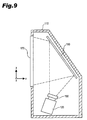
- Figs. 9, 10 illustrate one example of a conventional rear projection display device.
- Fig. 9 is a cross sectional view schematically illustrating a structure of a conventional rear projection display device
- Fig. 10 is a top plan view schematically illustrating a structure of a projection unit of the rear projection display device of Fig. 9.
- a coordinate system is used where a horizontal direction of a rectangle screen 170 is taken along an x- axis, a vertical direction of the screen 170 is taken along a y-axis, and a perpendicular direction to the screen 170 is taken along a z-axis.
- the rear projection display device includes a projection unit 120 arranged in a body 110.
- a projection lens 130 is arranged on a light emitting opening of the projection unit 120.
- a reflecting mirror 160 is arranged on an inner back surface of the body 110, and a transmission type diffusing screen 170 is arranged on the front of the body 110.
- Image light which is magnified and projected from the projection unit 120 through the projection lens 130 is reflected on the reflecting mirror 160, is irradiated onto a back surface of the diffusing screen 170, and then a picture is observed on the front surface of the diffusing screen 170.
- the projection unit 120 includes a white light source 121 comprising a lamp 121a and a reflector 121b.
- Dichroic mirrors 122, 123 split white light emitted from the white light source 121 into light of three colors.
- a first dichroic mirror 122 selectively reflects light of a red component (referred as red light hereinafter) out of the white light emitted from the lamp 121a and transmits light of other color components.
- a second dichroic mirror 123 selectively reflects light of a green component (referred as green light hereinafter). Green light out of the light which is transmitted through the first dichroic mirror 122 is selectively reflected on the second dichroic mirror 123 and is introduced to a liquid crystal panel 127g for green.
- Light of a blue component (referred as blue light hereinafter) out of the light transmitted through the second dichroic mirror 123 is introduced to a liquid crystal panel 127b for blue by reflecting mirrors 125, 126.
- the red light reflected on the first dichroic mirror 122 is introduced to a liquid crystal panel 127r for red by the first reflecting mirror 124.
- Color light respectively modulated at the liquid crystal panels 127r, 127g, and 127b is synthesized at a dichroic prism 128 and is emitted to the projection lens 130.
- Incident directions of the color light modulated at the liquid crystal panels 127r, 127g, and 127b to the dichroic prism 128 is set with consideration of color reproducibility at the dichroic prism 128.
- Light reflected on the dichroic prism 128 is S-polarized light, and light transmitted through the dichroic prism 128 is P-polarized light.
- S-polarized light is a linearly polarized light which the oscillation direction of the electric vector of light incident to a sample surface is vertical to a surface including a normal of the sample surface and a normal of wave surface which is a light traveling direction.
- P-polarized light is a linearly polarized light which the oscillation direction of the electric vector of light incident to a sample surface is included in an incident surface (a surface including a normal of the sample surface and a light traveling direction).
- the red light out of the light incident to the dichroic prism 128 is set to be S-polarized to a bonded surface 128x.
- a polarized light component which is perpendicular to an x-z plane is reflected on the bonded surface 128x.
- the green light is set to be P-polarized light to the bonded surfaces 128x, 128y.
- a polarized light component which is parallel to the x-z plane is transmitted through the bonded surface 128x, 128y.
- the blue light is set to be S-polarized light to the bonded surface 128y.
- a polarized light component which is perpendicular to the x-z plane is reflected on the bonded surface 128y. And then the red, green, and blue light is color-synthesized.
- the color-synthesized image light is irradiated from the projection lens 130 to the back surface of the screen 170 through the reflecting mirror 160.
- a rear projection display device capable of slantly irradiating image light to the screen 170 for reducing the depth of the device.
- a polarization direction of the projected image light to the screen 170 is set in the direction orthogonal with the polarization direction of the image light to the dichroic prism 128.
- the red light is P-polarized
- the green light is S-polarized
- the blue light is P-polarized.
- Fig. 6 is a table showing the reflectivity characteristic of light incident to the acrylic resin from the air. As shown in Fig. 6, when the image light is slantly projected on the screen 170, the reflectivity of P-polarized light to the screen 170 is lowered while the reflectivity of S-polarized light to the screen 170 increases.
- Fig. 8 presents the spectral luminous efficiency characteristics of a man. As shown in Fig. 8, the spectral luminous efficiency of man's eyes is the highest at around a wavelength of 555nm which corresponds to a color of green and a man is likely to recognize green light brighter in comparison with red and blue light.
- the reflectivity of the brightest green light at the screen 120 increases, and the brightness as a whole is lowered, and furthermore the image quality is degraded because of the reflected light.
- the present invention was made to solve the above problem and has an objective to provide a rear projection display device capable of improving brightness and image quality by improving the utilization efficiency of image light which is slantly projected on a screen.
- a rear projection display device of this invention comprises a light source lamp, color splitting means for splitting light emitted from the light source lamp into a plurality of color components, a plurality of liquid crystal panels for optically modulating each color light split by the color splitting means, color synthesizing means for synthesizing each of the color light modulated by the liquid crystal panels, and projection means for projecting image light which is color-synthesized by the color synthesizing means on a screen from slantly above or from slantly below.
- a polarization direction of at least a green component out of the image light irradiated on the screen is parallel to a vertical cross section of the screen.
- polarization direction adjusting means is provided for adjusting a polarization direction of at least the green component out of the image light synthesized by the color synthesizing means so that the polarization direction of at least the green component is parallel to the vertical cross section of the screen.
- This structure ensures that a polarization direction of the green component out of the image light synthesized by the color synthesizing means is adjusted so as to be parallel to a vertical cross section of the screen when the polarization direction of the green light is not parallel to the vertical cross section.
- polarization directions of all the color components of the image light irradiated on the screen are parallel to the vertical cross section of the screen.
- polarization direction adjusting means is provided for selectively adjusting a color component, of which a polarization direction is orthogonal with the vertical cross section of the screen, out of the image light synthesized by the color synthesizing means so that the polarization direction of the color component is parallel to the vertical cross section of the screen.
- This structure ensures that a color component having a polarization direction orthogonal with a vertical cross section of the screen, out of the image light synthesized by the color synthesizing means is selectively adjusted so that the polarization direction is parallel to the vertical cross section of the screen.
- a rear projection display device of this invention comprises a light source lamp, color splitting means for splitting light emitted from the light source lamp into a plurality of color components, a plurality of liquid crystal panels for optically modulating each color light split by the color splitting means, color synthesizing means for synthesizing each of the color light modulated by the liquid crystal panels, and projection means for projecting image light which is color-synthesized by the color synthesizing means on a screen from a slant side.
- a polarization direction of at least a green component out of the image light irradiated on the screen is parallel to a horizontal cross section of the screen.
- polarization direction adjusting means is provided for adjusting a polarization direction of at least the green component out of the image light irradiated on the screen so that the polarization direction of at least the green component is parallel to the horizontal cross section of the screen.
- This structure ensures that a polarization direction of the green component out of the image light synthesized by the color synthesizing means is adjusted so as to be parallel to a horizontal cross section of the screen even when the polarization direction of the green light is not parallel to the horizontal cross section.
- polarization directions of all the color components of the image light irradiated on the screen are parallel to the horizontal cross section of the screen.
- polarization direction adjusting means is provided for selectively adjusting a color component, of which polarization direction is orthogonal with the horizontal cross section of the screen, out of the image light synthesized by the color synthesizing means so that the polarization direction of the color component is parallel to the horizontal cross section of the screen.
- This structure ensures that a polarization direction of a color component out of the image light synthesized by the color synthesizing means is selectively adjusted so as to be parallel to a horizontal cross section of the screen.
- a rear projection display device of this invention comprises a light source lamp, color splitting means for splitting light emitted from the light source lamp into a plurality of color components, a plurality of liquid crystal panels for optically modulating the light of each color split by the color splitting means, color synthesizing means for synthesizing each of the color light modulated by the liquid crystal panels, and projection means for slantly projecting image light which is color-synthesized by the color synthesizing means on a screen.
- a polarization direction of at least a green component out of the image light irradiated on the screen is parallel to a plane including the image light irradiated on the screen and a normal of the screen.
- polarization direction adjusting means for adjusting a polarization direction of at least the green component out of the image light irradiated on the screen so that the polarization direction of at least the green component is parallel to the plane including the image light irradiated on the screen and the normal of the screen.
- This structure ensures that a polarization direction of the green component out of the image light synthesized by the color synthesizing means is adjusted so as to be parallel to a plane including the image light irradiated on the screen and a normal of the screen by the polarization direction adjusting means even when the polarization direction of the green light is not parallel to the plane including the image light irradiated on the screen and a normal of the screen.
- polarization directions of all the color components of the image light irradiated on the screen are parallel to the a plane including the image light irradiated on the screen and a normal of the screen.
- polarization direction adjusting means for selectively adjusting a color component, of which a polarization direction is orthogonal with the plane including the image light irradiated on the screen and the normal of the screen, out of the image light synthesized by the color synthesizing means so that the polarization direction of the color component is parallel to the plane including the image light irradiated on the screen and a normal of the screen.
- This structure ensures that a color component of which a polarization direction is orthogonal with a plane including image light irradiated on the screen and a normal of the screen out of the image light synthesized by the color synthesizing means is selectively adjusted so that the color component is made parallel to a plane including the image light irradiated on the screen and the normal of the screen.
- the polarization direction adjusting means comprises a retardation plate.
- the projection means includes a plurality of aspherical mirrors functioning as a lens.
- a rear projection display device of this invention which image light is irradiated to the back surface of the screen from slantly behind or slantly above and a picture is observed on a front surface of the screen
- the relation i-min ⁇ ⁇ ⁇ i-max is satisfied, where an angle of a maximum value i-max and a minimum value i-min is formed by a normal of a back surface of the screen and a principal ray of the image light irradiated on the back surface of the screen, and an angle ⁇ is obtained when the reflectivity of light, having a polarization direction parallel to the vertical cross section of the screen, to the back surface of the screen is minimum.
- light having a polarization direction parallel to a vertical cross section of a screen is irradiated on a back surface of the screen at an angle including the angle ⁇ at which the reflectivity to a normal of a back surface of the screen at the back surface of the screen is low.
- the relation j-min ⁇ ⁇ j-max is satisfied, where an angle of a maximum value j-max and a minimum value j-min are formed by a normal of a front surface of the screen and a principal ray of the image light irradiated on the front surface of the screen, and an angle ⁇ is obtained when the reflectivity of light, having a polarization direction parallel to the vertical cross section of the screen, to the front surface of the screen is minimum.
- light having a polarization direction parallel to a vertical cross section of a screen is irradiated on a front surface of the screen at an angle including the angle ⁇ at which the reflectivity to a normal of a back surface of the screen at the back surface of the screen is low.
- the screen includes a fresnel lens and the front surface of the screen is an inclined surface with a ring body shaped protrusion of the fresnel lens.
- the polarization direction of at least the green component out of the image light irradiated on the screen is parallel to the vertical cross section of the screen.
- a rear projection display device of this invention which image light is irradiated to the back surface of the screen from a slant side and a picture is observed on a front surface of the screen
- the relation i-min ⁇ ⁇ ⁇ i-max is satisfied, where an angle of a maximum value i-max and a minimum value i-min of is formed by a normal of a back surface of the screen and a principal ray of the image light irradiated on the back surface of the screen, and an angle ⁇ is obtained when the reflectivity of light, having a polarization direction parallel to the horizontal cross section of the screen, to the back surface of the screen is minimum.
- light having a polarization direction parallel to a horizontal cross section of a screen is irradiated on a back surface of the screen at an angle including the angle ⁇ at which the reflectivity to a normal of a back surface of the screen at the back surface of the screen is low.
- the relation j-min ⁇ ⁇ j-max is satisfied, where an angle of a maximum value j-max and a minimum value j-min is formed by a normal of a front surface of the screen and a principal ray of the image light irradiated on the front surface of the screen, and an angle ⁇ is obtained when the reflectivity of light, having a polarization direction parallel to the horizontal cross section of the screen, to the front surface of the screen is minimum.
- light having a polarization direction parallel to a horizontal cross section of a screen is irradiated on a front surface of the screen at an angle including the angle ⁇ at which the reflectivity to a normal of a back surface of the screen at the back surface of the screen is low.
- the screen includes a fresnel lens and the front surface of the screen is an inclined surface with a ring body shaped protrusion of the fresnel lens.
- the polarization direction of at least the green component out of the image light irradiated on the screen is parallel to the horizontal cross section of the screen.
- a rear projection display device of this invention which image light is slantly irradiated to the back surface of the screen and a picture is observed on a front surface of the screen
- the relation i-min ⁇ ⁇ ⁇ i-max is satisfied, where an angle of a maximum value i-max and a minimum value i-min is formed by a normal of a back surface of the screen and a principal ray of the image light irradiated on the back surface of the screen, and an angle ⁇ is obtained when the reflectivity of light, having a polarization direction parallel to a plane including image light irradiated on the back surface of the screen and a normal of the back surface of the screen, to the back surface of the screen is minimum.
- light having a polarization direction parallel to the plane including image light irradiated on the back surface of the screen and a normal of the back surface of the screen is irradiated on a back surface of the screen at an angle including the angle ⁇ at which the reflectivity to a normal of a back surface of the screen at the screen is low.
- the relation j-min ⁇ ⁇ j-max is satisfied, where an angle of a maximum value j-max and a minimum value i-min is formed by a normal of a front surface of the screen and a principal ray of the image light irradiated on the front surface of the screen, and an angle ⁇ is obtained when the reflectivity of light, having a polarization direction parallel to the plane including image light irradiated on the front surface of the screen and a normal of the front surface of the screen, to the front surface of the screen is minimum.
- light having a polarization direction parallel to a plane including image light irradiated on the front surface of the screen and a normal of the front surface of the screen is irradiated on a front surface of the screen at an angle including the angle ⁇ at which the reflectivity to a normal of a front surface of the screen at the front surface of the screen is low.
- the screen includes a fresnel lens and the front surface of the screen is an inclined surface with a ring body shaped protrusion of the fresnel lens.
- the polarization direction of at least the green component out of the image light irradiated on the screen is parallel to a plane including image light irradiated on the back surface of the screen and a normal of the back surface of the screen.
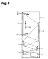
- Figs. 1 is a cross sectional view
- Fig. 2 is a front elevation; both schematically illustrate a structure of a rear projection display device.
- Figs. 3, 4 schematically illustrate a structure of a projection unit in the rear projection display device of Fig. 1;
- Fig. 3 is a top plan view, and
- Fig. 4 is a side view.
- Fig. 5 is an enlarged segmentary sectional view of a screen of the rear projection display device of Fig. 1.
- Fig. 6 is a graph of the reflectivity characteristic of light incident to acrylic resin from the air
- Fig. 7 is a graph of the reflectivity characteristic of light emitted from the acrylic resin to the air
- Fig. 8 is a graph of spectral luminous efficiency characteristics of a man.
- a rear projection display device of this invention includes a projection unit 2 for producing image light, a screen 7 for forming a picture when the image light is projected, first-fourth mirrors 3-6 for introducing the image light emitted from the projection unit 2 to the screen 7, and a body 1 for holding these elements incorporatively.
- An image forming system is composed of the first-third mirrors 3-5.
- the first mirror 3 has an aspherical concave shape
- the second and third mirrors 4, 5 have aspherical convex shapes.
- the shapes of the mirrors in the image forming system ensures corrections of aberration such as astigmatism and coma of image light and magnifications of the image light.
- the image light emitted from the projection unit 2 is successively reflected on the first-third mirrors 3-5, and is irradiated on the fourth mirror 6 which is arranged on an internal back surface of the body 1.
- the image light irradiated on the fourth mirror 6 of a flat plate shape is irradiated from slantly behind on a back surface of the screen 7 which is arranged on a front opening of the body 1, then a picture is formed.
- the projection unit 2 is one of three-plate type.
- a light source 21 comprises a reflector 21b and a metal halide lamp 21a.
- White light emitted from the light source 21 is splited into light of three colors by dichroic mirrors 22, 23.
- the first dichroic mirror 22 selectively reflects red light out of the white light emitted from the metal halide lamp 21a and transmits light of other color components.
- the second dichroic mirror 23 selectively reflects green light and transmits light of other color components.
- the white light emitted from the metal halide lamp 21a is reflected on the reflector 21b. Then, ultra violet ray and infrared ray in the light are eliminated at an UV/IR filter (not shown), and the white light is irradiated to the first dichroic mirror 22 at an angle of 45° .
- Red light reflected on the first dichroic mirror 22 is introduced to the first liquid crystal panel for red 27r by the first reflecting mirror 24.
- the light transmitted through the first dichroic mirror 22 is irradiated on the second dichroic mirror 23 at an angle of 45° .
- Green light out of the light transmitted the first dichroic mirror 22 is selectively reflected on the second dichroic mirror 23 and is introduced to the second liquid crystal panel for green 27g. Blue light, the rest of the light transmitted through the second dichroic mirror 23 is successively reflected on the second and third mirrors 25, 26, and is introduced to the third liquid crystal panel for blue 27b by the second and third reflecting mirrors 25, 26.
- the red light introduced to the first liquid crystal panel for red 27r is optically modulated according to image information of the red component, and is incident to the main surface 28r of the dichroic prism 28 for color synthesis.
- the green light introduced to the second liquid crystal panel for green 27g is optically modulated according to image information of the green component, and is incident to the main surface 28g of the dichroic prism 28 for color synthesis.
- the blue light introduced to the first liquid crystal panel for blue 27b is optically modulated according to image information of the blue component, and is incident to the main surface 28b of the dichroic prism 28 for color synthesis.
- the color light optically modulated by each of the liquid crystal panel 27r, 27g, and 27b with correspondence to each color information is color-synthesized by the dichroic prism 28.
- the color-synthesized image light is emitted from the main surface 28c of the dichroic prism 28.
- the polarization directions of the light is respectively rotated by an angle of 90° at a ⁇ /2 retardation plate 29, and the light is given to the image forming system.
- the red light out of the image light emitted from the main surface 28c of the dichroic prism 28 is S-polarized light to the bonded surface 28x
- the green light is P-polarized light to the bonded surfaces 28x, 28y
- the blue light is S-polarized light to the bonded surface 28y.
- the polarization directions are respectively rotated by an angle of 90° at the ⁇ /2 retardation plate 29, then the red light is turned into P-polarized light to the bonded surface 28x, the green light is turned into S-polarized light to the bonded surfaces 28x, 28y, and the blue light is turned into P-polarized light to the bonded surface 28y.
- the image light transmitted through the ⁇ /2 retardation plate 29 is successively reflected on the first-third mirrors 3-5 which compose the image forming system, and is irradiated to the fourth mirror 6 arranged on the back surface of the body 1.
- the shapes of the mirrors in the image forming system ensure corrections of aberration such as astigmatism and coma of the image light, and magnify the image light.
- the image light irradiated on the flat plate shaped fourth mirror 6 is irradiated to the back surface of the screen 7 from slantly below.
- the red light out of the image light irradiated on the back surface of the screen 7 is S-polarized to the screen 7, that is the polarization direction is vertical to the y-z plane.
- the green light is P-polarized to the screen 7, that is the polarization direction is parallel to the y-z plane.
- the blue light is S-polarized to the screen 7, that is the polarization direction is vertical to the y-z plane.
- the y-z plane is a vertical cross section of the screen 7.
- the screen 7 includes a fresnel lens screen 71 formed with acrylic resin and a lenticular lens screen 72.
- the image light reflected on the fourth mirror 6 is irradiated on a back surface 71a of the fresnel lens screen 71.
- An angle (i) formed by a normal A to the back surface 71a of the fresnel lens screen 71 and a principal ray of the image light irradiated thereon is i-max at maximum at upper corners C1, C2 of the fresnel lens screen 71 (see Fig. 1), and is i-min at minimum at a lower corner C3 (see Fig. 1).
- the first-fourth mirrors 3-6 are set so that i-max is to be 58.27° , and i-min is to be 32.27° .
- Fig. 6 is a graph for showing the reflectivity characteristic of light incident to acrylic resin from the air.
- the refractivity of the air is 1.00
- the refractivity of the acrylic resin is 1.492.
- the reflectivity of light irradiated to the acrylic resin forming the fresnel lens screen 71 from the air varies depending on an angle of incidence ⁇ 1, an angle formed by the light irradiated to the acrylic resin and a normal of the acrylic resin at a point where the light is irradiated.
- ⁇ 1 an angle formed by the light irradiated to the acrylic resin and a normal of the acrylic resin at a point where the light is irradiated.
- the angle ⁇ 1 is close to the minimum value ⁇ the reflectivity reduces.
- the angle ⁇ of the minimum value is an angle when P-component of the reflected light is zero and the reflected light is a plane polarized light. Such the angle of incidence is referred as polarization angle.
- an angle ⁇ is approximately 56° according to the above expression when the light is incident to the acrylic resin from the air.
- the reflectivity to the screen 7 of the red light and blue light as S-polarized light out of the image light irradiated to the back surface 71a of the fresnel lens screen 71 is higher than the reflectivity of light irradiated parallel to the normal A of the screen 7, and the light utilization efficiency decreases.
- the reflectivity of the green light as P-polarized light to the screen 7 out of the image light irradiated on the back surface 71a of the fresnel lens screen 71 is lower than the reflectivity of the light irradiated parallel to the normal A of the screen 7, and the light utilization efficiency increases.
- Fig. 8 indicates the visibility of various wavelengths, taking the visibility at the wavelength 555nm corresponding to the green as the reference.
- the visibility of the green is one
- the visibility of the wavelength 630nm corresponding to the red is approximately 0.265
- the visibility of the wavelength 470nm corresponding to the blue is approximately 0.091.
- the visibility of green light is remarkably higher than those of red and blue light.
- the lowered brightness caused by the S-polarized red and blue light to the screen 7 can be compensated by making the brightness of the P-polarized green light higher, and the brightness as a whole can be increased.
- light reflected on the back surface 71a of the fresnel lens screen 71 decreases, and a ghost caused by the reflected light can be reduced, and thus the image quality can be improved. It is preferred that all the component of light be P-polarized light to the screen 7.
- An angle (i) formed by a principal ray of the image light irradiated to the screen 7 and the normal A of the screen 7 is set to satisfy the below expression 2. Therefore, the utilization efficiency of P-polarized light component can be improved, leading to higher brightness.
- the image light transmitted through the back surface 71a of the fresnel lens screen 71 is refracted on the back surface 71a at an angle k1 corresponding to the Snel principle, and then is irradiated to a protruded inclined surface 71b formed in a ring body shape on an emitting side of the fresnel lens screen 71.
- An angle of an inclined surface 71b is set so that an angle (j) formed by a normal B to the inclined surface 71b of the fresnel lens screen 71 and a principal ray of the image light irradiated to the screen 71 is j-max at maximum and j-min at minimum on each protruded inclined surface 71b of the fresnel lens screen 71.
- an inclination ⁇ of each inclined surface 71b is set so that j-max is to be 38.36° and j-min is to be 22.57° .
- the reflectivity of light emitted from the acrylic resin composing the fresnel lens 71 to the air varies depending on an angle ⁇ 2 which is formed by the light traveling in the acrylic resin and the normal of the acrylic resin at a point where the light is emitted.
- ⁇ 2 which is formed by the light traveling in the acrylic resin and the normal of the acrylic resin at a point where the light is emitted.
- the reflectivity characteristic P' of light of which polarization direction is parallel to a plane including the light traveling in the acrylic resin and the normal of the acrylic resin at a point where the light is emitted the reflectivity decreases as the angle ⁇ 2 is made close to the minimum polarization angle ⁇ .
- the angle ⁇ is approximately 34° according to the expression 1.
- the reflectivity of red and blue light which is S-polarized to the screen 7 out of the image light irradiated to the inclined surface 71b with a ring body shaped protrusion on an emission side of the fresnel lens screen 71 is higher than the reflectivity of light irradiated in parallel to the normal B of the inclined surface 71b, and the light utilization efficiency is lowered.
- the reflectivity of the green light which is P-polarized to the screen 7 out of the image light irradiated to the inclined surface 71b is lower than the reflectivity of light irradiated parallel to the normal B of the inclined surface 71b, and the light utilization efficiency increases.
- the lowered brightness caused by the S-polarized red and blue light to the screen 7 is compensated by the increased brightness of the P-polarized green light to the screen 7, and the brightness as a whole can be improved.
- Reflected light at the inclined surface 71b of the fresnel lens screen 71 reduces, and a ghost produced by the reflected light can be reduced. Therefore, the image quality can be improved. It is preferred that all the color components be P-polarized light.
- Image light transmitted through the inclined surface 71b of the fresnel lens screen 7 is refracted on the inclined surface 71b at an angle k2 according to the Snel principle, and is irradiated to the lenticular lens screen 72. Then, a picture is formed by the diffusing action of the lenticular lens screen 72.
- the image light is irradiated from slantly behind of the screen 7.
- the image light may be irradiated from slantly side of the screen 7.
- the green light is adjusted so as to be P-polarized light to the screen 7, that is the polarization direction is parallel to the x-z plane.
- the polarization direction of the green light is adjusted so as to be parallel to the y-z plane. It is preferred that the polarization direction be parallel to a plane including a principal ray of the image light and the normal of a part at a point where the image light is irradiated.
- the polarization direction of the green light is adjusted so that the light turns from S-polarized light into P-polarized light to the screen 7 by the ⁇ /2 retardation plate 29.
- a narrow band retardation plate may be used for selectively adjusting the polarization direction of the green light so that the light turns from S-polarized light into P-polarized light to the screen 7.
- polarization directions of red and blue light do not change, and all the image light may be P-polarized light to the screen 7.
- the image forming system is composed of the first-third mirrors 3-5.
- the same effect can be gained when using a lens system.
- This invention can reduce reflection on a screen and improve the brightness by making at least a green component light P-polarized light to a screen when image light is slantly irradiated to the screen. Furthermore, a ghost phenomenon caused by reflected light on the screen is prevented and the image quality can be improved.
Landscapes
- Physics & Mathematics (AREA)
- General Physics & Mathematics (AREA)
- Projection Apparatus (AREA)
- Liquid Crystal (AREA)
Applications Claiming Priority (4)
| Application Number | Priority Date | Filing Date | Title |
|---|---|---|---|
| JP18789499 | 1999-07-01 | ||
| JP18789399 | 1999-07-01 | ||
| JP18789499 | 1999-07-01 | ||
| JP18789399 | 1999-07-01 |
Publications (2)
| Publication Number | Publication Date |
|---|---|
| EP1065559A1 true EP1065559A1 (fr) | 2001-01-03 |
| EP1065559B1 EP1065559B1 (fr) | 2008-04-23 |
Family
ID=26504626
Family Applications (1)
| Application Number | Title | Priority Date | Filing Date |
|---|---|---|---|
| EP00113899A Expired - Lifetime EP1065559B1 (fr) | 1999-07-01 | 2000-06-30 | Dispositif d'affichage à rétroprojection |
Country Status (3)
| Country | Link |
|---|---|
| US (3) | US6981771B1 (fr) |
| EP (1) | EP1065559B1 (fr) |
| DE (1) | DE60038655T2 (fr) |
Families Citing this family (29)
| Publication number | Priority date | Publication date | Assignee | Title |
|---|---|---|---|---|
| US20080055722A1 (en) * | 2006-08-31 | 2008-03-06 | Perkins Raymond T | Optical Polarization Beam Combiner/Splitter with an Inorganic, Dielectric Grid Polarizer |
| US20080055720A1 (en) * | 2006-08-31 | 2008-03-06 | Perkins Raymond T | Optical Data Storage System with an Inorganic, Dielectric Grid Polarizer |
| US20080055721A1 (en) * | 2006-08-31 | 2008-03-06 | Perkins Raymond T | Light Recycling System with an Inorganic, Dielectric Grid Polarizer |
| US7570424B2 (en) * | 2004-12-06 | 2009-08-04 | Moxtek, Inc. | Multilayer wire-grid polarizer |
| US20080055719A1 (en) * | 2006-08-31 | 2008-03-06 | Perkins Raymond T | Inorganic, Dielectric Grid Polarizer |
| US20080055549A1 (en) * | 2006-08-31 | 2008-03-06 | Perkins Raymond T | Projection Display with an Inorganic, Dielectric Grid Polarizer |
| US7630133B2 (en) * | 2004-12-06 | 2009-12-08 | Moxtek, Inc. | Inorganic, dielectric, grid polarizer and non-zero order diffraction grating |
| US7961393B2 (en) * | 2004-12-06 | 2011-06-14 | Moxtek, Inc. | Selectively absorptive wire-grid polarizer |
| US7800823B2 (en) * | 2004-12-06 | 2010-09-21 | Moxtek, Inc. | Polarization device to polarize and further control light |
| KR20060131081A (ko) * | 2005-06-15 | 2006-12-20 | 삼성전자주식회사 | 프로젝터용 착탈식 후면 투사 장치 |
| US20070091452A1 (en) * | 2005-10-25 | 2007-04-26 | Scott Lerner | Projection system and method |
| US7611250B2 (en) * | 2005-10-27 | 2009-11-03 | Chunghwa Picture Tubes, Ltd. | Projector |
| US8755113B2 (en) * | 2006-08-31 | 2014-06-17 | Moxtek, Inc. | Durable, inorganic, absorptive, ultra-violet, grid polarizer |
| US20080151198A1 (en) * | 2006-12-22 | 2008-06-26 | Texas Instruments Incorporated | System and method for slim projection displays |
| JP4909141B2 (ja) * | 2007-03-16 | 2012-04-04 | 三洋電機株式会社 | 投写型表示装置 |
| US20100103517A1 (en) * | 2008-10-29 | 2010-04-29 | Mark Alan Davis | Segmented film deposition |
| JP5360683B2 (ja) * | 2009-04-01 | 2013-12-04 | セイコーエプソン株式会社 | プロジェクター |
| US8248696B2 (en) | 2009-06-25 | 2012-08-21 | Moxtek, Inc. | Nano fractal diffuser |
| US8672427B2 (en) * | 2010-01-25 | 2014-03-18 | Pepsico, Inc. | Video display for product merchandisers |
| US8913321B2 (en) | 2010-09-21 | 2014-12-16 | Moxtek, Inc. | Fine pitch grid polarizer |
| US8611007B2 (en) | 2010-09-21 | 2013-12-17 | Moxtek, Inc. | Fine pitch wire grid polarizer |
| US8913320B2 (en) | 2011-05-17 | 2014-12-16 | Moxtek, Inc. | Wire grid polarizer with bordered sections |
| US8873144B2 (en) | 2011-05-17 | 2014-10-28 | Moxtek, Inc. | Wire grid polarizer with multiple functionality sections |
| US8922890B2 (en) | 2012-03-21 | 2014-12-30 | Moxtek, Inc. | Polarizer edge rib modification |
| US9563114B2 (en) | 2013-05-20 | 2017-02-07 | Sharp Kabushiki Kaisha | Display device |
| JP2015055856A (ja) * | 2013-09-13 | 2015-03-23 | 大日本印刷株式会社 | 背面投射型表示装置 |
| US9632223B2 (en) | 2013-10-24 | 2017-04-25 | Moxtek, Inc. | Wire grid polarizer with side region |
| JP6331366B2 (ja) * | 2013-12-05 | 2018-05-30 | コニカミノルタ株式会社 | 投影光学系用プリズムおよびそれを用いた光学系 |
| KR102479811B1 (ko) | 2016-06-13 | 2022-12-23 | 삼성전자주식회사 | 공기 조화기 및 공기 조화기의 제어방법 |
Citations (5)
| Publication number | Priority date | Publication date | Assignee | Title |
|---|---|---|---|---|
| US3848980A (en) * | 1971-08-24 | 1974-11-19 | Polaroid Corp | Projector apparatus and system employing unique screen |
| US4200365A (en) * | 1977-07-13 | 1980-04-29 | H. K. Productions Limited | Display and reproduction of color |
| US5048949A (en) * | 1987-11-26 | 1991-09-17 | Casio Computer Co., Ltd. | Liquid crystal projector |
| US5090800A (en) * | 1990-05-24 | 1992-02-25 | Fuji Photo Film Co., Ltd. | Projector having a liquid crystal display panel |
| WO1999013378A1 (fr) * | 1997-09-09 | 1999-03-18 | Minnesota Mining And Manufacturing Company | Afficheur a projection par transparence |
Family Cites Families (23)
| Publication number | Priority date | Publication date | Assignee | Title |
|---|---|---|---|---|
| US4516837A (en) * | 1983-02-22 | 1985-05-14 | Sperry Corporation | Electro-optical switch for unpolarized optical signals |
| US4544946A (en) * | 1983-04-21 | 1985-10-01 | Rca Corporation | Vertical color shift correction in a rear projection television screen |
| JPH01120192A (ja) * | 1987-11-04 | 1989-05-12 | Seiko Epson Corp | 投写型表示装置 |
| US5097323A (en) * | 1988-01-25 | 1992-03-17 | Casio Computer Co., Ltd. | Liquid crystal projector |
| US4995718A (en) * | 1989-11-15 | 1991-02-26 | Honeywell Inc. | Full color three-dimensional projection display |
| US5285287A (en) * | 1991-06-14 | 1994-02-08 | Mitsubishi Denki Kabushiki Kaisha | Projecting method for picture display apparatus |
| JP2786796B2 (ja) * | 1993-06-23 | 1998-08-13 | シャープ株式会社 | プロジェクター |
| US5506642A (en) * | 1993-12-20 | 1996-04-09 | Fujitsu Limited | Projector with plastic mirror |
| JP2939860B2 (ja) | 1995-01-24 | 1999-08-25 | カシオ計算機株式会社 | 投影型液晶表示装置 |
| US5751384A (en) | 1995-05-23 | 1998-05-12 | The Board Of Regents Of The University Of Colorado | Color polarizers for polarizing an additive color spectrum along a first axis and it's compliment along a second axis |
| JP3637931B2 (ja) | 1995-09-25 | 2005-04-13 | ソニー株式会社 | プロジェクタ装置 |
| JPH10186547A (ja) * | 1996-10-30 | 1998-07-14 | Seiko Epson Corp | 投写型表示装置 |
| US6089718A (en) * | 1996-10-30 | 2000-07-18 | Seiko Epson Corporation | Projection display device |
| JPH1164973A (ja) | 1997-08-20 | 1999-03-05 | Sanyo Electric Co Ltd | 背面投写型表示装置 |
| JPH11242118A (ja) * | 1998-02-25 | 1999-09-07 | Seiko Epson Corp | 偏光分離素子、偏光変換素子および投写型表示装置 |
| US6449089B1 (en) * | 1998-03-30 | 2002-09-10 | 3M Innovative Properties Company | Rear projection screen with enhanced contrast |
| JP3622500B2 (ja) * | 1998-05-20 | 2005-02-23 | 株式会社富士通ゼネラル | 液晶プロジェクタ装置 |
| US6082861A (en) * | 1998-09-16 | 2000-07-04 | International Business Machines Corporation | Optical system and method for high contrast projection display |
| JP2000227578A (ja) * | 1998-11-12 | 2000-08-15 | Fujitsu Ltd | 投写型表示装置 |
| US6217174B1 (en) * | 1999-01-28 | 2001-04-17 | Richard M. Knox | Image projection |
| US6369010B1 (en) | 1999-12-01 | 2002-04-09 | Vinings Industries, Inc. | Method and composition for preventing pitch deposits in paper mills using resinous mechanical pulps |
| DE60135889D1 (de) * | 2000-03-17 | 2008-11-06 | Hitachi Ltd | Bildanzeigevorrichtung |
| US6805447B2 (en) * | 2000-10-13 | 2004-10-19 | Nec Viewtechnology Ltd. | Rear projection display device and projecting method used for the same |
-
2000
- 2000-06-30 DE DE60038655T patent/DE60038655T2/de not_active Expired - Lifetime
- 2000-06-30 EP EP00113899A patent/EP1065559B1/fr not_active Expired - Lifetime
- 2000-06-30 US US09/608,067 patent/US6981771B1/en not_active Expired - Lifetime
-
2005
- 2005-08-05 US US11/197,414 patent/US7329004B2/en not_active Expired - Lifetime
-
2006
- 2006-08-08 US US11/500,403 patent/US7264357B2/en not_active Expired - Lifetime
Patent Citations (5)
| Publication number | Priority date | Publication date | Assignee | Title |
|---|---|---|---|---|
| US3848980A (en) * | 1971-08-24 | 1974-11-19 | Polaroid Corp | Projector apparatus and system employing unique screen |
| US4200365A (en) * | 1977-07-13 | 1980-04-29 | H. K. Productions Limited | Display and reproduction of color |
| US5048949A (en) * | 1987-11-26 | 1991-09-17 | Casio Computer Co., Ltd. | Liquid crystal projector |
| US5090800A (en) * | 1990-05-24 | 1992-02-25 | Fuji Photo Film Co., Ltd. | Projector having a liquid crystal display panel |
| WO1999013378A1 (fr) * | 1997-09-09 | 1999-03-18 | Minnesota Mining And Manufacturing Company | Afficheur a projection par transparence |
Also Published As
| Publication number | Publication date |
|---|---|
| US20060038963A1 (en) | 2006-02-23 |
| DE60038655T2 (de) | 2009-06-04 |
| US20060285082A1 (en) | 2006-12-21 |
| DE60038655D1 (de) | 2008-06-05 |
| US7264357B2 (en) | 2007-09-04 |
| US6981771B1 (en) | 2006-01-03 |
| US7329004B2 (en) | 2008-02-12 |
| EP1065559B1 (fr) | 2008-04-23 |
Similar Documents
| Publication | Publication Date | Title |
|---|---|---|
| EP1065559B1 (fr) | Dispositif d'affichage à rétroprojection | |
| JP4063538B2 (ja) | 背面投写型表示装置 | |
| JP3105805B2 (ja) | 広画角液晶プロジェクションレンズシステム | |
| JP5280628B2 (ja) | 液晶ディスプレイのスクリーン用の背面照明系及び対応する表示デバイス | |
| US10495959B2 (en) | Projector and illumination system thereof | |
| US8123366B2 (en) | Light source with truncated ellipsoidal reflector | |
| JP6830222B2 (ja) | ヘッドアップディスプレイ | |
| CN111201478A (zh) | 虚像投射装置 | |
| US6637891B2 (en) | Optical system of liquid crystal projector | |
| US6439725B1 (en) | Optical system of a liquid crystal projector for reducing total length of the system | |
| JP2007052451A (ja) | 背面投写型表示装置 | |
| JP3895907B2 (ja) | 背面投写型表示装置 | |
| JP4045005B2 (ja) | カラー画像投影装置 | |
| JPH04195030A (ja) | プロジェクタ | |
| KR100354149B1 (ko) | 헤드 마운트 디스플레이용 광학 시스템 | |
| JP2001042461A (ja) | 背面投写型表示装置 | |
| US6705730B2 (en) | Picture display device | |
| JP2004252489A (ja) | 背面投写型表示装置 | |
| JP2879554B2 (ja) | 投写型表示装置 | |
| US20050146786A1 (en) | Rear projection image display apparatus | |
| JP2002023162A (ja) | プロジェクションシステム | |
| JPH10260474A (ja) | 背面投写型表示装置 | |
| JPH11174371A (ja) | 光学装置及び光学装置を備える表示装置 | |
| JP2610087B2 (ja) | 照明光学系および投写型液晶表示装置 | |
| JP2001042427A (ja) | 背面投写型表示装置 |
Legal Events
| Date | Code | Title | Description |
|---|---|---|---|
| PUAI | Public reference made under article 153(3) epc to a published international application that has entered the european phase |
Free format text: ORIGINAL CODE: 0009012 |
|
| 17P | Request for examination filed |
Effective date: 20001110 |
|
| AK | Designated contracting states |
Kind code of ref document: A1 Designated state(s): DE FR GB |
|
| AX | Request for extension of the european patent |
Free format text: AL;LT;LV;MK;RO;SI |
|
| AKX | Designation fees paid |
Free format text: DE FR GB |
|
| 17Q | First examination report despatched |
Effective date: 20050512 |
|
| 17Q | First examination report despatched |
Effective date: 20050512 |
|
| GRAP | Despatch of communication of intention to grant a patent |
Free format text: ORIGINAL CODE: EPIDOSNIGR1 |
|
| GRAS | Grant fee paid |
Free format text: ORIGINAL CODE: EPIDOSNIGR3 |
|
| GRAA | (expected) grant |
Free format text: ORIGINAL CODE: 0009210 |
|
| RAP1 | Party data changed (applicant data changed or rights of an application transferred) |
Owner name: SANYO ELECTRIC CO., LTD. |
|
| AK | Designated contracting states |
Kind code of ref document: B1 Designated state(s): DE FR GB |
|
| REG | Reference to a national code |
Ref country code: GB Ref legal event code: FG4D |
|
| REF | Corresponds to: |
Ref document number: 60038655 Country of ref document: DE Date of ref document: 20080605 Kind code of ref document: P |
|
| ET | Fr: translation filed | ||
| PLBE | No opposition filed within time limit |
Free format text: ORIGINAL CODE: 0009261 |
|
| STAA | Information on the status of an ep patent application or granted ep patent |
Free format text: STATUS: NO OPPOSITION FILED WITHIN TIME LIMIT |
|
| 26N | No opposition filed |
Effective date: 20090126 |
|
| PGFP | Annual fee paid to national office [announced via postgrant information from national office to epo] |
Ref country code: FR Payment date: 20100709 Year of fee payment: 11 |
|
| PGFP | Annual fee paid to national office [announced via postgrant information from national office to epo] |
Ref country code: GB Payment date: 20100630 Year of fee payment: 11 Ref country code: DE Payment date: 20100625 Year of fee payment: 11 |
|
| GBPC | Gb: european patent ceased through non-payment of renewal fee |
Effective date: 20110630 |
|
| REG | Reference to a national code |
Ref country code: FR Ref legal event code: ST Effective date: 20120229 |
|
| REG | Reference to a national code |
Ref country code: DE Ref legal event code: R119 Ref document number: 60038655 Country of ref document: DE Effective date: 20120103 |
|
| PG25 | Lapsed in a contracting state [announced via postgrant information from national office to epo] |
Ref country code: FR Free format text: LAPSE BECAUSE OF NON-PAYMENT OF DUE FEES Effective date: 20110630 Ref country code: DE Free format text: LAPSE BECAUSE OF NON-PAYMENT OF DUE FEES Effective date: 20120103 |
|
| PG25 | Lapsed in a contracting state [announced via postgrant information from national office to epo] |
Ref country code: GB Free format text: LAPSE BECAUSE OF NON-PAYMENT OF DUE FEES Effective date: 20110630 |