EP1064124B1 - Stanzvorrichtung für stahlständer - Google Patents
Stanzvorrichtung für stahlständer Download PDFInfo
- Publication number
- EP1064124B1 EP1064124B1 EP99907049A EP99907049A EP1064124B1 EP 1064124 B1 EP1064124 B1 EP 1064124B1 EP 99907049 A EP99907049 A EP 99907049A EP 99907049 A EP99907049 A EP 99907049A EP 1064124 B1 EP1064124 B1 EP 1064124B1
- Authority
- EP
- European Patent Office
- Prior art keywords
- die
- punch
- shaped frame
- frame portion
- support member
- Prior art date
- Legal status (The legal status is an assumption and is not a legal conclusion. Google has not performed a legal analysis and makes no representation as to the accuracy of the status listed.)
- Expired - Lifetime
Links
- 238000004080 punching Methods 0.000 title claims description 39
- 229910000831 Steel Inorganic materials 0.000 title claims description 31
- 239000010959 steel Substances 0.000 title claims description 31
- 230000007246 mechanism Effects 0.000 claims description 130
- 238000009433 steel framing Methods 0.000 claims description 4
- 238000009435 building construction Methods 0.000 claims description 3
- 239000012530 fluid Substances 0.000 claims description 3
- 238000004891 communication Methods 0.000 claims description 2
- 238000013461 design Methods 0.000 description 6
- 210000002105 tongue Anatomy 0.000 description 5
- 238000010276 construction Methods 0.000 description 3
- HSFWRNGVRCDJHI-UHFFFAOYSA-N alpha-acetylene Natural products C#C HSFWRNGVRCDJHI-UHFFFAOYSA-N 0.000 description 2
- 125000002534 ethynyl group Chemical group [H]C#C* 0.000 description 2
- 238000003780 insertion Methods 0.000 description 2
- 230000037431 insertion Effects 0.000 description 2
- 239000002184 metal Substances 0.000 description 2
- 238000003825 pressing Methods 0.000 description 2
- 229910001335 Galvanized steel Inorganic materials 0.000 description 1
- 241000256602 Isoptera Species 0.000 description 1
- 241000017363 Schefflera morototoni Species 0.000 description 1
- 230000000994 depressogenic effect Effects 0.000 description 1
- 238000009429 electrical wiring Methods 0.000 description 1
- 239000008397 galvanized steel Substances 0.000 description 1
- JEIPFZHSYJVQDO-UHFFFAOYSA-N iron(III) oxide Inorganic materials O=[Fe]O[Fe]=O JEIPFZHSYJVQDO-UHFFFAOYSA-N 0.000 description 1
- 230000014759 maintenance of location Effects 0.000 description 1
- 239000000463 material Substances 0.000 description 1
- 238000000034 method Methods 0.000 description 1
- 238000009428 plumbing Methods 0.000 description 1
- 230000000717 retained effect Effects 0.000 description 1
- 238000010008 shearing Methods 0.000 description 1
- 238000004513 sizing Methods 0.000 description 1
Images


Classifications
-
- B—PERFORMING OPERATIONS; TRANSPORTING
- B21—MECHANICAL METAL-WORKING WITHOUT ESSENTIALLY REMOVING MATERIAL; PUNCHING METAL
- B21D—WORKING OR PROCESSING OF SHEET METAL OR METAL TUBES, RODS OR PROFILES WITHOUT ESSENTIALLY REMOVING MATERIAL; PUNCHING METAL
- B21D28/00—Shaping by press-cutting; Perforating
- B21D28/24—Perforating, i.e. punching holes
- B21D28/243—Perforating, i.e. punching holes in profiles
-
- Y—GENERAL TAGGING OF NEW TECHNOLOGICAL DEVELOPMENTS; GENERAL TAGGING OF CROSS-SECTIONAL TECHNOLOGIES SPANNING OVER SEVERAL SECTIONS OF THE IPC; TECHNICAL SUBJECTS COVERED BY FORMER USPC CROSS-REFERENCE ART COLLECTIONS [XRACs] AND DIGESTS
- Y10—TECHNICAL SUBJECTS COVERED BY FORMER USPC
- Y10T—TECHNICAL SUBJECTS COVERED BY FORMER US CLASSIFICATION
- Y10T83/00—Cutting
- Y10T83/808—Two tool pairs, driver for one pair moves relative to driver for other pair
- Y10T83/822—Punch and shear
-
- Y—GENERAL TAGGING OF NEW TECHNOLOGICAL DEVELOPMENTS; GENERAL TAGGING OF CROSS-SECTIONAL TECHNOLOGIES SPANNING OVER SEVERAL SECTIONS OF THE IPC; TECHNICAL SUBJECTS COVERED BY FORMER USPC CROSS-REFERENCE ART COLLECTIONS [XRACs] AND DIGESTS
- Y10—TECHNICAL SUBJECTS COVERED BY FORMER USPC
- Y10T—TECHNICAL SUBJECTS COVERED BY FORMER US CLASSIFICATION
- Y10T83/00—Cutting
- Y10T83/869—Means to drive or to guide tool
- Y10T83/8788—Tool return mechanism separate from tool advance mechanism
-
- Y—GENERAL TAGGING OF NEW TECHNOLOGICAL DEVELOPMENTS; GENERAL TAGGING OF CROSS-SECTIONAL TECHNOLOGIES SPANNING OVER SEVERAL SECTIONS OF THE IPC; TECHNICAL SUBJECTS COVERED BY FORMER USPC CROSS-REFERENCE ART COLLECTIONS [XRACs] AND DIGESTS
- Y10—TECHNICAL SUBJECTS COVERED BY FORMER USPC
- Y10T—TECHNICAL SUBJECTS COVERED BY FORMER US CLASSIFICATION
- Y10T83/00—Cutting
- Y10T83/869—Means to drive or to guide tool
- Y10T83/8821—With simple rectilinear reciprocating motion only
- Y10T83/8841—Tool driver movable relative to tool support
- Y10T83/8843—Cam or eccentric revolving about fixed axis
-
- Y—GENERAL TAGGING OF NEW TECHNOLOGICAL DEVELOPMENTS; GENERAL TAGGING OF CROSS-SECTIONAL TECHNOLOGIES SPANNING OVER SEVERAL SECTIONS OF THE IPC; TECHNICAL SUBJECTS COVERED BY FORMER USPC CROSS-REFERENCE ART COLLECTIONS [XRACs] AND DIGESTS
- Y10—TECHNICAL SUBJECTS COVERED BY FORMER USPC
- Y10T—TECHNICAL SUBJECTS COVERED BY FORMER US CLASSIFICATION
- Y10T83/00—Cutting
- Y10T83/929—Tool or tool with support
- Y10T83/9411—Cutting couple type
- Y10T83/9423—Punching tool
- Y10T83/9428—Shear-type male tool
Definitions
- the present invention relates to an apparatus for punching steel studs to form holes of sufficient size to allow wiring and piping to extend therethrough, and sufficiently lacking sharp tongues or flanges that would damage the wiring or piping.
- Steel frame homes and structures are becoming widespread.
- Steel frames have many advantages over traditional wooden frames.
- Steel frames are termite, rust, and rot proof. Further, steel frames are non-combustible, energy efficient, and resistant to poor weather and active seismic conditions.
- Steel framing is made from light gauge galvanized steel cold formed into C-shaped cross-section components. Design changes are minimized by choosing components that match lumber dimensions, particularly when converting a wooden frame design to a steel frame design. Studs come in all sizes; however, most builders use 0,092 m (3 5/8 inch) and 0,139 m (5 1 ⁇ 2 inch) sizes that match wood frame dimensions.
- One way to form these holes is to use an acetylene torch to cut the holes. Using an acetylene torch to cut holes in steel studs is inconvenient for a builder.
- Another way to form holes in steel studs is with a large mechanical lever type piercer and die tool, such as that described in U.S. Patent No. 5,287,716 issued to Szulc. Because a builder may not realize where it is desired to form holes in the steel studs until the frame is at least partially constructed, forming the holes is difficult. Many times, it is not possible to position the large lever type tool about the steel frame to form the holes because of the large size of the lever type tool, and because of the space constraints of the partially constructed frame.
- FR-A-2707539 discloses a punching apparatus as per the precharacterising portion of claim 1.
- the device is hand-operated and has a fixed working stroke.
- JP-A-6000519 describes a shearing machine which has a punch attached to a piston rod and a die fixed to a die support.
- the die support is rotatable about an axis parallel to the axis of the piston rod to facilitate an insertion of a part to be punched.
- an apparatus for punching knock-outs out of light gauge steel framing studs used in building construction to form holes of sufficient size to allow building wiring and piping to extend therethrough comprises a compact hand-held frame having a generally C-shaped portion with spaced apart ends located along a working axis, and a handle for gripping by a user.
- a punch and die assembly includes a punch and a die mounted opposite each other at the ends of the C-shaped frame portion. The punch and the die are mounted for movement relative to each other along the working axis.
- An actuatable driving mechanism is mounted to the frame. The driving mechanism is operable to drive the punch and die assembly over a working stroke range between a de-actuated and an actuated position. In the de-actuated position, the punch and the die are spaced apart with the stud positioned therebetween. In the actuated position, the punch extends into the die cavity by punching through the stud to form the punched hole.
- the invention provides a gross adjust mechanism configured for moving the punch and the die relative to each other over a gross adjust stroke range significantly larger than that required to punch through the stud between an open position and a closed position.
- the open position allows the positioning of the stud between the punch and the die.
- the closed position is based on the working stroke range to cause punching of the punch through the stud upon actuation of the driving mechanism.
- the C-shaped frame portion includes first and second halves. Each half includes a respective end of the C-shaped frame portion.
- the gross adjust stroke range is defined along the working axis.
- the gross adjust mechanism includes a slide member connecting the first and second halves of the C-shaped frame portion. The slide member allows movement of the die toward and away from the punch along the working axis.
- the gross adjust mechanism further includes a lock device for unlocking the slide member to allow movement of the slide member, and for locking the slide member to prevent movement of the slide member during actuation of the driving member.
- both ends of the C-shaped frame portion include undercut jaw portions to allow positioning of differently shaped studs between the punch and the die.
- an apparatus for punching knock-outs out of light gauge steel framing studs used in building construction to form holes of sufficient size to allow building wiring and piping to extend therethrough comprises a compact hand held frame, a punch and die assembly, and a gross adjust mechanism.
- the gross adjust mechanism includes a shaft oriented along the working axis and having first and second ends.
- a punch is mounted to the shaft first end, and the shaft slidably cooperates with the frame to move the punch relative to the die over the gross adjust stroke range between the open and closed positions.
- a driving mechanism comprises a lever pivotally attached to the frame, and having a grip portion proximate the handle enabling the user to squeeze the handle and lever together.
- An advance sear cooperates with the shaft and the lever to cause the shaft to incrementally advance the punch toward the die each time the lever grip portion is squeezed toward the handle.
- a retract sear cooperates with the shaft and the frame to enable the shaft to freely advance while preventing the shaft from retracting after each incremental advance.
- embodiments of the present invention provide a compact hand held tool for punching steel studs to form holes of sufficient size to allow wiring and piping to extend therethrough.
- the gross adjust mechanism and undercut jaws provide tool versatility, particularly for punching holes in steel studs which are already secured within a partially constructed frame.
- the punch is configured with respect to the die cavity such that punching the hole produces a knock-out.
- an annular gap between the punch and the die cavity, when the punch is extended into the die cavity is sufficiently small such that the punched hole is substantially flangeless. That is, the hole sufficiently lacks sharp tongues or flanges that would damage the wiring or piping.
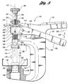
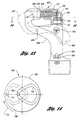
- an apparatus for punching steel studs is generally indicated at 10.
- the apparatus 10 includes a compact hand held frame 12.
- the frame 12 has a generally C-shaped portion 14 with first and second ends 16 and 18, respectively.
- the first end 16 and second end 18 are spaced apart and located along a working axis 20 for receiving a stud therebetween.
- a handle 22 is provided for gripping by a user when operating the apparatus 10.
- a punch and die assembly 24 includes a punch 26 and a die 28.
- Punch 26 is mounted to first end 16 of C-shaped frame portion 14.
- Die 28 is mounted to second end 18 of C-shaped frame portion 14, opposite punch 26.
- the stud 30 is shown between punch 26 and die 28.
- Punch 26 and die 28 are mounted for movement relative to each other along the working axis 20.
- Die 28 has a cavity 32 so that punch 26 may extend into cavity 32 of die body 28, punching through stud 30 during operation.
- An actuatable driving mechanism such as an electric motor 36 ( Figure 1), is mounted to the frame 12.
- Electric motor 36 ( Figure 1) has a drive shaft 38.
- a gear reduction assembly 40 such as a cycloidal gear set, has an input portion 42 and an output portion 44. Input portion 42 of gear reduction assembly 40 is driven by drive shaft 38.
- Output portion 44 of gear reduction assembly 40 drives punch and die assembly 24 via a suitable cam mechanism, such as cam mechanism 46.
- cam mechanism 46 includes a slot 48 located on output portion 44 of gear reduction assembly 40.
- Punch 26 includes a punch body 56 secured to a punch head 58 by a fastener 60.
- the punch body 56 is supported by a bearing 62.
- Cam mechanism 46 further includes a roller pin 50 which cooperates with slot 48 to impart reciprocal driving motion to punch 26.
- electric motor 36 is powered by a suitable power source such as a battery source 64.
- a suitable power source such as a battery source 64.
- embodiments of the present invention may include a power cord for connection to a conventional power outlet.
- other types of driving mechanisms may be utilized.
- a turbine may be used as best shown in Figure 2, or a handle and lever incremental advance mechanism may be used as best shown in Figure 3, all of which will be described in detail herein.
- other driving mechanisms may be used as is to be appreciated by one of ordinary skill in the art.
- the driving mechanism may be a turbine 80.
- Turbine 80 drives drive shaft 38 and is powered from a compressed fluid source (not specifically illustrated).
- a valve 82 is actuatable by trigger 70, and actuates turbine 80 by opening turbine input 84, and deactuates turbine 80 by closing turbine input 84.
- An inlet connector 86 is located on frame 12 for connection to a suitable fluid source such as a compressed air tank.
- Gear reduction assembly 40 may provide more speed reduction in the turbine driven embodiment than in the electric motor driven embodiment to accommodate for increased drive shaft speed in the turbine.
- the apparatus is configured such that the punched holes are of sufficient size to allow wiring and piping to extend therethrough.
- the punch is configured with respect to the die to produce a knock-out when punching the hole.
- One technique that may be utilized to produce knock-outs is sizing the punch relative to the die cavity such that an annular gap between the punch and the die cavity, when the punch is extended into the die cavity, is sufficiently small such that the punched hole produces a knock-out and is substantially flangeless. That is, a substantially flangeless punched hole is sufficiently lacking sharp tongues or flanges that would damage the wiring or piping intended to pass therethrough.
- a gross adjust mechanism 90 is configured for moving the punch 26 and the die 28 relative to each other over a gross adjust stroke range significantly larger than that required to punch through the stud between an open position indicated at 66 ( Figure 2), and a closed position indicated at 68 ( Figure 1).
- C-shaped frame portion 14 includes a first half 92 and a second half 94.
- Electric motor 36 ( Figure 1) or turbine 80 ( Figure 2) is disposed in first housing half 92.
- Second housing half 94 is connected to first housing half 92 by a lockable slide member 96 fixed to second housing half 94, and a corresponding guide slot 98 within first housing half 92.
- Another slide member 102 is fixed to second housing half 94 and cooperates with a corresponding guide slot 104 in first housing half 92. Sliding members 96 and 102 allow sliding movement of the die 28 toward and away from the punch 26 along the working axis 20, over the gross adjust stroke range.
- a lock device for gross adjust mechanism 90 is generally indicated at 106.
- a trigger 108 is operable to unlock the device.
- Trigger 108 connects to arm 110 which engages lock member 112.
- lock member 112 engages a recess 114 in slide member 96 to lock the slide member 96 and prevent movement of the slide members 96 and 102 during actuation of the driving mechanism (electric motor 36, turbine 80, or another suitable driving mechanism).
- Actuation of trigger 108 which is indicated by arrow 116, causes movement of arm 110 as indicated by arrow 118, causing lock member 112 to disengage from recess 114.
- Disengagement of lock member 112 from recess 114 unlocks the slide member 96 to allow sliding movement of die 28 toward and away from punch 26.
- both ends 16 and 18 of C-shaped frame portion 14 include undercut jaw portions 126 and 128 to allow positioning of differently shaped studs between punch 26 and die 28.
- the gross adjust stroke range is significantly larger than that required to punch through the stud to allow positioning of differently shaped studs between punch 26 and die 28.
- the working stroke range is not significantly larger than that required to punch through the stud to allow a short powerful stroke for the punch and die assembly.
- gross adjust mechanism 90 may be constructed in a variety of other ways in addition to that utilizing slide members 96 and 102.
- the gross adjust stroke range may be defined along a plane substantially perpendicular to the working axis.
- a lockable hinge member connecting the first and second halves of the C-shaped frame portion allows hinged movement of the die toward and away from the punch along the plane.
- the lock device allows unlocking of the hinge member to move the hinge member through the plane, and allows locking of the hinge member to prevent movement of the hinge member during operation of the driving mechanism.
- the gross adjust mechanism may include a lockable pivot member connecting the first and second halves of the C-shaped frame portion and allowing arcuate pivotal movement of the punch toward and away from the die along a plane parallel to the working axis.
- a lock device allows unlocking and locking of the pivot member.
- the loading experienced by the gross adjust mechanism may be very extreme.
- the slide members are a preferred version thereof.
- the gross adjust mechanism may be omitted, provided that the working stroke range is sufficiently large so as to allow positioning of a stud between the punch and die.
- the use of a gross adjust mechanism is preferred so that the working stroke range may be shortened, increasing the applied force from punch 26.
- undercut jaws are preferably employed in conjunction with the gross adjust mechanism to provide increased tool versatility.
- cam mechanism which is illustrated as a slot and pin arrangement.
- a spring may be disposed within the frame to urge the punch away from the die.
- a cam lobe mounted to the output portion of the gear reduction assembly may force the punch through the stud against the bias of the spring upon actuation of the driving mechanism.
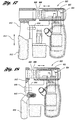
- Apparatus 130 includes compact hand held frame 132 which has a generally C-shaped portion 134.
- C-shaped portion 134 has first and second ends 136 and 138, respectively.
- the first and second ends 136 and 138, respectively, are located in a spaced apart relationship along a working axis 140.
- a handle 142 is sized to be grasped by one hand of the user of the press, and extends generally radially outward from the working axis 140.
- a punch and die assembly includes a punch 144 mounted at first end 136 of C-shaped frame portion 134, and a die 146 mounted at second end 138 of C-shaped frame portion 134.
- a stud 148 is received between punch 144 and die 146.
- Die 146 has a cavity 150 for receiving punch 144 during the punching operation.
- a lever 154 is pivotally attached to frame 132 by pivot pin 156.
- Lever 154 is provided with a grip portion 158, and a fork portion defined by a pair of generally parallel, spaced apart fork members 160.
- the gross adjust mechanism for apparatus 130 includes a shaft 162 oriented along the working axis 140 and having first and second ends 164 and 166, respectively.
- the gross adjust mechanism is configured for moving the punch 144 and the die 146 relative to each other over a gross adjust stroke range between open and closed positions.
- the open position allows the positioning of the stud 148 between the punch 144 and the die 146, and is shown at 170.
- the closed position shown in phantom at 172 the punch 144 and die 146 are near to or in contact with stud 148 while the punch and die assembly is deactuated.
- punch 144 Upon actuation, punch 144 extends into die cavity 150 by punching through stud 148, as shown in phantom at 174.
- the motion of the punch and die assembly, over both the gross adjust range and the working stroke range, is indicated by arrow 176.
- Each fork member 160 of lever 154 is provided with a cam surface 178 for cooperation with an advance sear 180.
- a retract sear 182 cooperates with shaft 162 and frame 132 to enable the shaft 162 to freely advance while preventing the shaft 162 from retracting after each incremental advance.
- the advance sear 180 cooperates with the shaft 162 and the lever 154 to incrementally advance shaft 162 upon pulling lever 154 toward handle 142.
- First end 136 of shaft 162 has a bore 184 which provides means for attachment of punch 144.
- Second end 138 of C-shaped frame portion 134 has a bore 186 which provides means for attachment of die 146.
- suitable attachment means such as a threaded connection or conventional fastener could be used to facilitate the attachment of punch 144 and die 146.
- a palm button 188 is provided on the shaft second end 138. This enables a user to manually advance the shaft over the gross adjust stroke range.
- Shaft 162 has a tubular region in which a retract spring 190 is oriented.
- Pin 192 is attached to frame 132 and extends radially inwardly through a slot 194 formed in shaft 162 to engage retract spring 190. As the shaft 162 is advanced, spring 190 abuts pin 192 causing the spring to compress.
- Advance sear 180 is biased in a direction opposite the direction of shaft advance by advance sear spring 196. After each incremental advance of the shaft 162 and advance sear 180, the advance sear spring 196 returns the advance sear to the position shown at 180.
- Retract sear 182 is biased toward a normally locked orientation by retract sear spring 198.
- retract sear 182 initially moves slightly with the shaft or a sufficient distance to cause the retract sear to rotate relative to the shaft pivoting about the engagement with the frame so that the shaft and the retract sear become unlocked. It is during the relative movement of the retract sear and the frame that the retract sear spring 198 is compressed.
- the unlocked orientation of the retract sear is shown in phantom at 206.
- Stud 148 is positioned between punch 144 and die 146.
- the user presses down on palm button 188 causing retract sear spring 198 to compress sufficiently such that retract sear 182 releases the shaft 162.
- the user presses down on palm button 188 to move punch 144 and die 146 over the gross adjust range, until punch 144 and die 146 are near to and preferably in contact with stud 148.
- retract sear spring 198 urges retract sear 182 such that the retract sear 182 bites into the shaft 162, preventing the moving apart of the punch 144 and die 146.
- advance sear 180 Upon release of the lever, advance sear 180 returns to its at rest position, and shaft 162 is maintained in its incrementally advanced position by retract sear 182 maintaining its bite into shaft 162. Each time the lever grip portion is squeezed toward the handle, as described above, the advance sear cooperates with the shaft and the lever to cause the shaft to incrementally advance. After initial positioning of punch 144, punch 144 is incrementally advanced into die cavity 150 over the working stroke range, until stud 148 is punched. Once stud 148 is properly punched, it is necessary to open the punch die assembly to facilitate removal of the stud.
- retract sear 182 In order to open the punch and die assembly, the user can either directly release the retract sear 182 by pressing down against spring 198, or the user can push lever 154 away from handle 142 to cause a second cam surface 210 of lever 154 to engage retract sear 182.
- retract spring 190 axially biases shaft 162 to the retract position. Therefore, once retract sear 182 is released, the shaft 162 will naturally return to the withdrawn position.
- Advance sear 180 and retract sear 182 are preferably formed of a hard steel sheet material having a hardness greater than that of shaft 162 to facilitate the biting of the shaft by the sears.
- a compact hand held frame 212 has a generally C-shaped portion 214 with a punch end 216 and a die end 218, spaced apart along a working axis 220.
- a handle 222 is provided for gripping by a user.
- a punch and die assembly 224 includes a punch 226 and a die 228.
- a stud 230 is punched by extending the punch 226 into the die cavity 232.
- a die support member 234 is slidably received in the die end 218 of the C-shaped frame portion 214. Die 228 is received in die support member 234.
- apparatus 210 includes a cam mechanism 236 having a slot 238 and roller pin 240 operable to drive punch 226 as indicated by arrow 244 upon actuation of trigger 246, as shown by arrow 248.
- Trigger 246 actuates a suitable driving mechanism, such as, for example, an electric motor powered by a battery 250. Other driving mechanisms may be used, as previously described.
- Gross adjust mechanism 254 includes the die support member 234 and a cooperating lever 256.
- Lever 256 is pivotally attached to the die end 218 of the C-shaped frame portion 214.
- An arcuate slot 260 is formed on each side of the lever 256.
- Each slot 260 is configured with an inflection at one end 262.
- a follower pin 264 is located on each side of die support member 234 and extends outwardly from the die support member periphery.
- Each slot 260 receives a respective follower pin 264 to guide the die support member 234 and die 228 relative to the punch 226 over the gross adjust stroke range, as the lever 256 is pivoted.
- multiple pins and slots may alternatively be provided, or other arrangements may be provided for connecting lever 256 to die support member 234.
- the slot may have other shapes capable of providing a locked position, for example, as shown in Figure 16.
- the die, die support member, and lever are indicated at 228, 234, and 256, respectively.
- the lever 256 is pivoted such that the pin 264 is positioned in the inflected end 262 of slot 260 to secure the punch 226 and die 228 in the closed position during actuation of the driving member to punch the stud.
- the die, die support member, and lever are indicated at 266, 268, and 270, respectively.
- the lever 270 is pivoted such that the pin 272 is positioned in the non-inflected end 274 of slot 260 to place the punch 226 and die 228 into the opened position to allow insertion of a stud.
- embodiments of the present invention provide a compact, hand held apparatus for punching steel studs to form holes of sufficient size to allow wiring and piping to extend therethrough.
- the compactness of the apparatus provides great versatility during use thereof. For example, many times during construction of steel frame homes and structures, there is a need to punch holes in steel studs or other steel components after partial assembly of the frame or structure. In these situations, space constraints may be very severe, so severe that a conventional large lever type punch is inadequate in those space constraints.
- the compact, hand held punch of the present invention facilitates punching holes in areas having severe space constraints.
- the compactness of embodiments of the present invention is advantageous in that the punch is sized to form large holes for wiring and piping.
- the preferred punch is not of the convex piercer type which generally has a pointed shape and leaves sharp flanges or tongues but is instead generally concave so as to eliminate the undesired tongues and flanges by producing a knock-out.
- Assembly 300 includes a punch holder 302 defined at the punch end of the C-shaped frame, and a die holder 304 defined at the die end of the C-shaped frame.
- a punch 306 is connected to a reciprocating member 308.
- Reciprocating member 308 is driven by a driving mechanism that may take any number of forms, and is not specifically shown.
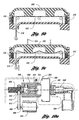
- a die 310 is mounted opposite punch 306. Die 310 has a body defining a die cavity 312 into which punch 306 is extended to punch through the stud 340 to form the punched hole by producing a knock-out.
- punch 306 is encircled by a sleeve 316 that slidingly engages punch 306.
- a spring seat 318 is fixed with reciprocatable member 308, and a spring 320 biases sleeve 316 toward die 310 such that upon actuation of the driving mechanism (not specifically shown), sleeve 316 engages die body 310 prior to the extension of punch 306 into die cavity 312 to punch out the stamped piece or knock-out.
- Die body 310 defines an opening 322 in communication with die cavity 312. Opening 322 is sized such that the knock-out 342 exists die cavity 312 by passing through opening 322, as best shown in Figure 5c. It is to be appreciated that opening 322 may be a very convenient feature during use of a stud punching apparatus of the present invention.
- die body 310 is rotatably mounted to the C-shaped frame portion such that rotation of die body 310 allows a user to selectively position opening 322 with respect to die holder 304. Die body 310 is retained to die holder 304 by retention clip 324.
- a lock mechanism is configured with respect to die body 310 and die holder 304 such that die body 310 may be selectively rotated to a desired position with respect to die holder 304, and locked in the desired position by the lock mechanism.
- the lock mechanism may be a ball and detent arrangement including a plurality of detents 326 circumferentially spaced around die body bottom surface 328 and a ball 330 biased by a spring 332. That is, ball 330 is biased by spring 332 into any one of detents 326, depending on the position of die body 310.
- a rod number 334 may extend into die cavity 312 such that punch 306 may press member end 338 to disengage a lock mechanism of the gross adjust mechanism.
- the lock mechanism may be the slide lock mechanism illustrated in Figures 1 and 2, or any other locking mechanism as is appreciated by one of ordinary skill in the art.
- punch 306 and die 310 are in the closed position, with punch 306 in the deactuated position.
- the punch is in the actuated position extending into die 310.
- knock-out 342 exists die cavity 312 through opening 322.
- Apparatus 360 includes a C-shaped frame portion 362, a punch 364, and a die 366.
- a driving mechanism 368 which may be a motor or air turbine or other device as described previously, is connected through a gear reduction mechanism 369 to a drive shaft 370.
- Drive shaft 370 has a pinion 372 at its end.
- a cylinder cam 374 is fixed to punch 364, and engages a bearing 376.
- Cylinder cam 374 has an inside gear 378 engaging drive shaft pinion 372.
- a pin 380 is affixed to C-shaped frame portion 362, and a slot 382 is defined by the outer surface of cylinder cam 374.
- Pin 380 engages slot 382, and slot 382 is shaped such that actuating the driving mechanism causes pinion 372 to rotate cylinder cam 374 such that pin 380 follows slot 382, driving punch 364 over the working stroke range and preferably (as shown) over the gross adjust stroke range, as well.
- slot 382 has a curved path, such as a generally sinusoidal path, such that when punch 364 is approaching die 366, movement of punch 364 is relatively fast compared to movement of punch 364 when stud 384 is engaged.
- slot 382 is defined by cylinder cam 374; however, it is to be appreciated that a slot may be defined by the C-shaped frame portion, with the pin protruding from cylinder cam 374.
- pin 380 is a roller pin. As best shown in Figure 6c, pin 380 travels along slot 382 to drive punch 364 into die 366, putting the cylinder cam in position 390, through stud 392.
- Apparatus 400 includes a punch 402 and die 404.
- Punch 402 is connected to a reciprocating member 406, driven by a driving mechanism 408.
- Stud 410 is positioned between punch 402 and die 404.
- a die support member 412 is slidably received in the die end 413 of the frame.
- a spring 414 biases die support member 412 at a spring seat 416 to the open position, as best shown in Figure 7a.
- An electromagnetic 418 is operative to urge die support member 412 against the bias of spring 414 to the closed position, upon actuation of the electromagnetic 418, as best shown in Figure 7b. After electromagnetic 418 is actuated, driving mechanism 408 is used to drive the punch 402 into die 404.
- apparatus 400 employs a lock mechanism so that the punch and die assembly remains in the closed position and continued actuation of electromagnetic 418 is not required.
- a lock 420 is biased into opening 422 when die support 412 is in the closed position.
- a release shaft 424 is pushed at its end 426 by punch 402 after stud 410 has been punched, as best shown in Figure 7c.
- Release member 424 engages member 428 at an interface with cam angled surfaces on both member 424 and 428 abutting each other. Abutment of the cam angled surfaces pushes member 428 against the bias of spring 432 to resultantly push lock member 420 against the bias of spring 434 and unlock die support member 412, as best shown in Figure 7c.
- Apparatus 460 includes a punch 462, reciprocating member 464, a driving mechanism 466, and a die 468.
- a stud 470 is positioned between punch 462 and die 468.
- a die support member 472 is slidably received in the die end of the frame.
- Die support member 472 includes portion 474 having a cam angled surface 476.
- a rack member 478 has a cam angled surface 480 abutting angled surface 476 of die support portion 474.
- Rack 478 is driven by a driving mechanism 482 having a drive shaft with a pinion 484 engaging rack 478.
- driving mechanism 482 employs a gear reduction mechanism, as is preferred in other embodiments of the present invention.
- Rack number 478 and pinion 484 are ranged such that rotation of the drive shaft in a first direction causes the rack member cam service 480 to slide against the die support member complimentary cam service 476, moving die 468 to the closed position, as best shown in Figure 8b. Further, rotation of the drive shaft in a second direction allows the die to retreat to the open position, shown in Figure 8a.
- Apparatus 500 include punch 502, die 504, driving member 506 engaging punch 502, and driving mechanism 508, which preferably includes a gear reduction mechanism.
- a stud 510 is positioned between punch 502 and die 504.
- Apparatus 500 includes a die support member 512, with a lock member 514 and locking arrangement 516 similar to that shown in Figures 8a and 8b in some aspects.
- a pulley arrangement includes wire 518 extending about rollers 520 and 522 and connecting to die support member 512 at attachment point 524.
- a trigger arrangement 530 at the apparatus handle is used to pull a portion 532 of wire 518.
- the trigger 530 is not squeezed.
- the trigger 530 is squeezed in a direction indicated by arrow 534, against the bias of spring 536, pushing wire portion 532 and resultantly pulling wire portion 518 (see Figures 9a - 9c).
- the pulley arrangement configuration urges die support member 512 to cause die 504 to move to the closed position, as best shown in Figure 9b.
- the pulley arrangement may be configured in a variety of ways, and it is not required that squeezing trigger 530 closes the punch and die assembly. That is, squeezing the trigger may be employed to open the punch and die assembly by changing the location of the attachment point 524 to die support 512.
- an emergency release button 552 is provided such that elongated member 554 pivots about connection 556 to disengage locking mechanism 516.
- Apparatus 580 has a punch 582 and a die 584 for punching pieces of stud 586. Further, apparatus 580 employs a reciprocating member 588, and a driving mechanism 590. Die 584 is held by die support member 592. Die support member 592, similar to those embodiments described previously, may be locked by lock member 594 and locking mechanism 596 into the closed position. In this embodiment, die support member 592 has a threaded member 600. A nut 602 is received on threaded member 600. Nut 602 is mounted for rotation within the C-shaped frame portion while remaining axially stationary with respect to the C-shaped frame portion.
- a driving mechanism 604 has a drive shaft 606 that drives a pulley 608.
- a second pulley 610 is defined by nut 602, and a drive belt 612 transfers motion of drive shaft 606 to nut 602.
- Rotation of nut 602 in a first direction causes die 584 to move toward the closed position.
- Rotation of nut 602 in a second direction causes die 584 to move toward the open position.
- other mechanisms may be employed to impart the driving motion of drive shaft 606 to nut 602, such as gears.
- a measuring device for use with a punching apparatus in accordance with the present invention is generally indicated at 620.
- Device 620 is a detachable telescopic leg.
- Telescopic leg 620 may be formed, for example, with an inner rod member 622 received within a sleeve member 624.
- lock members 626 are provided for locking member 622 with respect to sleeve 624 to fix the length of telescopic leg 620.
- Telescopic leg 620 may be connected to an apparatus 630 when punching a hole in a stud 632 by, for example, a threaded end on the leg that is received in a threaded aperture on the apparatus.
- telescopic leg 620 may then be used to assure that holes punched into additional studs 634 and 636 will be at the same level as a hole punched into stud 632. As such, during construction, one may be assured that piping easily passes through the aligned holes.
- the leg may include a plurality of rod members that cooperate together, with a lock located at the interface of each adjacent pair of rod members.
- Apparatus 670 includes a frame 671, a punch 672, and a die 674.
- Apparatus 670 is driven by a driving mechanism 676 connected through a gear reduction mechanism 678 to drive a threaded member 680.
- Threaded member 680 drives a cam mechanism 681 that has threads on its inside such that rotation of threaded member 680 in a first direction causes mechanism 681 to move upward, and such that rotation of threaded member 680 in the other direction causes mechanism 681 to move downward.
- Frame member 682 has a roller 684 connected thereto. Roller 684 rides on cam mechanism 681 to pivot frame member 682 about pivot connection 686.
- Frame member 682 is pivoted such that punch 672 engages die 674 to punch through the stud and produce a knock-out. In the other direction, frame member 682 pivots to open sufficiently to allow a stud to be positioned between punch 672 and die 674.
- the fully opened position for frame member 682 is indicated in phantom at 692, with the corresponding fully retracted position of the cam mechanism indicated in phantom at 690.
- a release mechanism may be operated by sliding switch 694 to allow frame member 682 to be further slid away from punch 672 to allow an even wider opening to position back to back studs therebetween, as shown in phantom at 698. Sliding switch 694 releases slide bar 696 to allow sliding of frame member 682.
- driving mechanism 676 may be operated to turn in either direction by lever switch 688.
- Apparatus 640 includes a generally C-shaped compact hand-held frame 642, with a punch 644 (having an actuated position shown in phantom at 645) and a die 646 at ends of the C-shaped portion.
- a gross adjust mechanism is composed of frame member 648 which is employed to allow movement of die 646 into and out of a working or closed position.
- Frame member 648 pivots about pivotal attachment 650 between a closed position, shown at 648, and an open position shown in phantom at 652.
- the closed position 648 for the member is configured such that member 648 engages lockable release mechanism 654 into slot 655.
- Mechanism 654 may be in the form of push button that is depressed to unlock member 648 after a punching operation is complete, to push the tab out of slot 655.
- Mechanism 654 preferably automatically locks when member 648 is pivoted to the closed position.
- push button 656 causes a driving mechanism 700 to cause punch 644 to drive through a stud into die 646.
- push button 656 is covered when the pivotable frame member is pivoted to the open position, indicated in phantom at 652.
- Driving mechanism 700 is a motor (or turbine) connected through a gear reduction mechanism to a cam plate 702.
- cam plate 702 includes a slot 704.
- the gear reduction assembly drives cam plate 702 to rotate plate 702 as indicated by arrow 712.
- a pin 706 is affixed to punch holder 707 and engages slot 704.
- cam plate 702 rotates, the rotational movement of cam plate 702 is converted into linear movement of pin 706, causing punch 644 to reciprocate.
- the slot causes the punch to have a lower velocity and resultingly more mechanical advantage near the fully extended position, while moving the punch at greater velocity over the gross adjust range or non-working portion of the stroke.
- the slot is shown in a preferred shape, other shapes for the slot are appreciated by those of ordinary skill in the art. For example, a circular slot may be used in the alternative.
- FIGS 15 and 16 illustrate another alternative of the present invention.
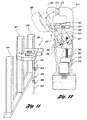
- a steel stud punch is generally indicated at 750.
- Apparatus 750 includes frame 752 having handle 754, with punch 756 held in punch holder 758 which is driven by driving mechanism 760.
- the other side of the frame includes a handle 770 with a slot 772 on plate 773 which is fixed to handle 770.
- a pin 774 on die holder 776 cooperates with slot 772 to provide a gross adjust mechanism for die 778.
- frame 752 includes a slot 790 that cooperates with slot 772 and pin 774.
- pin 774 slides through slots 790 and 772 to move die 778.
- Apparatus 800 includes frame 802 enclosing driving mechanism 804 for driving punch 806 into die 808.
- a frame member 810 supports die 808, and has a handle 812.
- Member 810 is mounted for sliding movement with respect to frame member 802, as indicated by arrow 814.
- a lock mechanism 816 is used to secure member 810 in a working position with die 808 aligned with punch 806.
- a user slides member 810 out of the way to allow positioning of a workpiece adjacent punch 806, and then slides member 810 to place die 808 in the working position.
- Apparatus 900 includes frame 902 enclosing driving mechanism 904.
- Mechanism 904 drives punch 906 into die 908.
- Die 908 is held in a frame member 910 with a handle 912.
- Frame member 910 is pivotally attached to frame portion 914 by a pivot pin 916.
- apparatus 900 of Figure 18 provides a gross adjust mechanism by utilizing pivotal movement of member 910 to move die 908 away from punch 906 to allow positioning of a workpiece therebetween.
- a suitable locking mechanism such as ball and detent mechanism 918 is provided to lock rod member 910 in a working position prior to punching through the workpiece.
Landscapes
- Engineering & Computer Science (AREA)
- Mechanical Engineering (AREA)
- Perforating, Stamping-Out Or Severing By Means Other Than Cutting (AREA)
- Punching Or Piercing (AREA)
Claims (25)
- Vorrichtung (10) zum Stanzen von Ausnehmungen aus im Hochbau verwendeten Leichtbaustahlrahmenpfosten, zur Bildung von Löchern ausreichender Größe, um zu ermöglichen, dass Bauverkabelungen und Rohrleitungen durch diese verlaufen, wobei die Vorrichtung umfasst:gekennzeichnet durch einen Grobeinstellmechanismus (90), welcher dazu ausgebildet ist, den Stanzer (26) und das Gesenk (28) relativ zueinander über einen Grobeinstellhubbereich zu bewegen, der im signifikanten Maße größer ist als der, der zum Stanzen durch den Pfosten zwischen einer offenen Position (66), die die. Positionierung des Pfostens zwischen dem Stanzer (26) und dem Gesenk (28) erlaubt, und einer geschlossenen Position (68) auf Grundlage des Arbeitshubbereichs, um ein Stanzen des Stanzers (26) durch den Pfosten beim Betätigen des Antriebsmechanismus zu bewirken, benötigt wird.einen kompakten Handrahmen (12) mit einem im Allgemeinen C-förmigen Abschnitt (14) mit voneinander im Abstand gelegenen Enden (16, 18), welche entlang einer Arbeitsachse (20) positioniert sind, um zwischen sich einen Pfosten aufzunehmen, sowie mit einem Griff (22) zum Ergreifen durch einen Benutzer;eine Stanzer-GesenK-Anordnung (24) mit einem Stanzer (26) und einem Gesenk (28), welche einander gegenüberliegend an den Enden (16, 18) des C-förmigen Rahmenabschnitts (14) angebracht sind, wobei der Stanzer (26) und das Gesenk (28) für eine Bewegung relativ zueinander entlang der Arbeitsachse (20) angebracht sind, wobei das Gesenk (28) einen einen Hohlraum definierenden Körper aufweist undder Stanzer (26) in Bezug auf den Hohlraum (32) so ausgebildet ist,dass ein Stanzen eines Lochs eine Ausnehmung erzeugt;einen betätigbaren Antriebsmechanismus, welcher an dem Rahmen (12) angebracht ist und zum Antreiben der Stanzer-Gesenk-Anordnung (24) über einen Arbeitshubbereich zwischen einer unbetätigten Position, in welcher der Stanzer (26) und das Gesenk (28) einen Abstand zueinander aufweisen, wobei der Pfosten zwischen ihnen positioniert ist, und einer betätigten Position, in welcher sich der Stanzer (26) in den Gesenkhohlraum hinein erstreckt, indem er durch den Pfosten stanzt, um das gestanzte Loch zu bilden, betreibbar ist, wobei der Arbeitshubbereich nicht wesentlich größer ist, als der, welcher zum Stanzen durch den Pfosten benötigt wird;
- Vorrichtung (10) nach Anspruch 1, wobei der Antriebsmechanismus ferner umfasst:einen Elektromotor (36), welcher an dem Rahmen (12) angebracht ist und eine Antriebswelle (38) aufweist;eine Untersetzungsanordnung (40) mit einem Eingangsabschnitt (42), welcher durch die Antriebswelle (38) angetrieben wird, und einem Ausgangsabschnitt (44); undeinen Kurvenmechanismus (46), welcher durch den Ausgangsabschnitt (44) der Untersetzungsanordnung (40) angetrieben wird, wobei der Kurvenmechanismus (46) die Stanzer-Gesenk-Anordnung (24) über den Arbeitshubbereich antreibt.
- Vorrichtung (10) nach Anspruch 1, wobei der Antriebsmechanismus ferner umfasst:eine Turbine (80), welche an dem Rahmen (12) angebracht ist undeinen Eingang (86) zum Verbinden mit einer Fluidquelle sowie eine Antriebswelle (38) aufweist;eine Untersetzungsanordnung (40) mit einem Eingangsabschnitt (42), welcher durch die Antriebswelle (38) angetrieben wird, und einem Ausgangsabschnitt (44); undeinen Kurvenmechanismus (46), welcher durch den Ausgangsabschnitt (44) der Untersetzungsanordnung (40) angetrieben wird, wobei der Kurvenmechanismus (46) die Stanzer-Gesenk-Anordnung (24) über den Arbeitshubbereich antreibt.
- Vorrichtung (10) nach einem der vorhergehenden Ansprüche, wobei der C-förmige Rahmenabschnitt 14 eine erste und eine zweite Hälfte (92, 94) umfasst, wobei jede Hälfte ein jeweiliges Ende (16, 18) des C-förmigen Rahmenabschnitts (14) umfasst, wobei der Grobeinstellmechanismus (90) ferner umfasst:ein blockierbares Schiebeelement (96), welches die erste und die zweite Hälfte (92, 94) des C-förmigen Rahmenabschnitts (14) verbindet und durch Bewegung des Schiebeelements (96) eine Schiebebewegung des Gesenks (28) in Richtung des Stanzers (26) und von dem Stanzer (26) weg entlang der Arbeitsachse (20) ermöglicht undeine Blockiereinrichtung (106) zum Entsperren des Schiebeelements (96), um eine Bewegung des Schiebeelements (96) zu ermöglichen, und zum Blockieren des Schiebeelements (96), um eine Bewegung des Schiebeelements (96) zu verhindern, und zwar während einer Betätigung des Antriebsmechanismus.
- Vorrichtung (10) nach Anspruch 4, wobei wenigstens ein Ende des C-förmigen Rahmenabschnitts (14) einen unterhölten Abschnitt (126, 128) aufweist um ein Positionieren von unterschiedlich geformten Pfosten zwischen dem Stanzer (26) und dem Gesenk (28) zu ermöglichen.
- Vorrichtung (10) nach Anspruch 5, wobei beide Enden (16, 18) des C-förmigen Rahmenabschnitts (14) unterhölte Abschnitte (126, 128) aufweisen, um ein Positionieren von unterschiedlich geformten Pfosten zwischen dem Stanzer (26) und dem Gesenk (28) zu ermöglichen.
- Vorrichtung (130) nach einem der Ansprüche 1 bis 3, wobei der Grobeinstellmechanismus (90) ferner umfasst:einen Schaft (162), welcher entlang der Arbeitsachse (140) orientiert ist und ein erstes und ein zweites Ende (164, 166) aufweist, wobei der Stanzer (26) an dem ersten Ende (164) des Schafts angebracht ist und der Schaft (162) mit dem Rahmen (132) verschiebbar zusammenarbeitet, um den Stanzer (144) relativ zu dem Gesenk (146) über den Grobeinstellhubbereich zwischen der offenen und der geschlossenen Position (170, 172) zubewegen; und
wobei der Antriebsmechanismus ferner umfasst:einen Hebel (154), welcher schwenkbar an dem Rahmen (132) angebracht ist und welcher einen Griffabschnitt (158) nahe dem Handgriff (142) aufweist, der es dem Benutzer ermöglicht, den Handgriff (142) und den Hebel (154) zusammenzudrücken,ein Vorschubklemmelement (180), welches mit dem Schaft (162) und dem Hebel (154) zusammenwirkt, um zu bewirken, dass der Schaft (162) den Stanzer (144) jedesmal, wenn der Hebelgriffabschnitt (158) zu dem Handgriff (142) hin gedrückt wird, schrittweise zu dem Gesenk (146) hin verschiebt;ein Rückzugsklemmelement (182), welches mit dem Schaft (162) und dem Rahmen (132) zusammenwirkt, um dem Schaft (162) zu ermöglichen, sich frei vorwärts zu schieben, während es es den Schaft (162) daran hindert, sich nach jedem schrittweisen Vorschub zurückzuziehen. - Vorrichtung (210) nach einem der Ansprüche 1 bis 3, wobei der Grobeinstellmechanismus (254) ferner umfasst:wobei der Schlitz (260) an einem Ende so ausgebildet ist, dass der Stanzer (226) und der Gesenkhohlraum (232) in der geschlossenen Position gesichert sind, wenn der Hebel (256) geschwenkt ist, um den Stift in der Biegung des Schlitzes (260) zu positionieren.ein Gesenkhalteelement (234), welches in dem Gesenkende (218) des C-förmigen Rahmenabschnitts (214) verschiebbar aufgenommen ist, wobei das Gesenk (228) in dem Gesenkhalteelement (234) aufgenommen ist;einen Stift (264), welcher sich aus dem Rand des Halteelements (234) nach außen erstreckt; undeinen Hebel (256), welcher schwenkbar an dem Gesenkende des C-förmigen Rahmenabschnitts (214) angebracht ist, wobei der Hebel (256) einen gebogenen Schlitz (260) aufweist, welcher den Stift (264) darin aufnimmt, um das Gesenk (228) relativ zu dem Stanzer (226) über den Grobeinstellhubbereich zwischen der offenen und der geschlossenen Position zu führen, wenn der Hebel (256) geschwenkt wird;
- Vorrichtung (10) nach Anspruch 2, wobei der Elektromotor (36) durch eine Batteriequelle (64) betrieben wird.
- Vorrichtung (10) nach einem der vorhergehenden Ansprüche, wobei der Gesenkkörper (310) eine Öffnung (322) definiert, welche mit dem Hohlraum (312) in Verbindung steht, wobei die Öffnung (322) so bemessen ist, dass die Ausnehmung (340) den Gesenkhohlraum (312) durch Hindurchtreten durch die Öffnung (322) verlässt; und wobei die Ausnehmung den Hohlraum (312) durch Hindurchtreten durch die Öffnung (322) verlässt.
- Vorrichtung (10) nach Anspruch 10, wobei der Gesenkkörper (310) an dem C-förmigen Rahmenabschnitt (14) drehbar angebracht ist, sodass eine Drehung des Gesenkkörpers (310) es dem Benutzer ermöglicht. die Öffnung in Bezug auf den C-förmigen Rahmenabschnitt (14) wahlweise zu positionieren.
- Vorrichtung (10) nach Anspruch 11, ferner umfassend:einen Verriegelungsmechanismus, welcher in Bezug auf den Gesenkkörper (310) und den C-förmigen Rahmenabschnitt (14) so ausgbildet ist, dass der Gesenkkörper (310) wahlweise in eine gewünschte Postion in Bezug auf den C-förmigen Rahmenabschnitt (14) gedreht werden kann und in der gewünschten Position durch den Verriegelungsmechanismus verriegelt werden kann.
- Vorrichtung (10) nach Anspruch 12, wobei der Verriegelungsmechanismus umfasst:einen Kugelrastmechanismus (330, 326), welcher eine Mehrzahl von verriegelten Positionen für den Gesenkkörper (310) in Bezug auf den C-förmigen Rahmenabschnitt (14) bereitstellt.
- Vorrichtung (10) nach Anspruch 10 ferner umfassend:eine Hülse (316) welche den Stanzer (306) umgibt und den Stanzer (306) verschiebbar in Eingriff nimmt; undeine Feder (320), welche die Hülse (316) zu dem Gesenk (310) hin beaufschlagt, sodass bei einer Betätigung des Antriebsmechanismus die Hülse (316) mit dem Gesenkkörper (310) vor dem Ausstanzen der Ausnehmung (342) in Eingriff kommt.
- Vorrichtung (360) nach Anspruch 1, ferner umfassend:eine Antriebswelle (370) mit einem Ritzel (372) an ihrem Ende;einen Zylinderkurventräger (374), welcher an dem Stanzer (364) befestigt ist und einen Innenmechanismus (378) aufweist, der das Antriebswellenritzel (374) in Eingriff nimmt, wobei der Zylinderkurventräger (374) eine Außenfläche aufweist;einen Stift (380), welcher an einem/an einer von dem C-förmigen Rahmenabschnitt (362) und der Zylinderkurventrägeraußenfläche befestigt ist; undeinen Schlitz (382), welcher durchiden, anderen/die andere von dem C-förmigen Rahmenabschnitt (362) und der Zylinderkurventrägeraußenfläche begrenzt ist wobei der Stift (380) in den Schlitz (382) eingreift und der Schlitz (382) so geformt ist, dass ein Betätigen des Antriebsmechanismus (368) bewirkt, dass das Ritzel (372) den Zylinderkurveträger (374) so dreht, dass der Stift (380) dem Schlitz (382) folgt.
- Vorrichtung (360) nach Anspruch 15, wobei der Stift (380) an dem C-förmigen Rahmenabschnitt (362) positioniert ist und der Schlitz (382) an der Zylinderkurventrägeraußenfläche positioniert ist.
- Vorrichtung nach Anspruch 16, wobei der Stift (380) die Form einer Rolle hat.
- Vorrichtung (400) nach einem der Ansprüche 1 bis 3, wobei der Grobeinstellmechanismus (90) umfasst:ein Gesenkhalteelement (412), welches in dem Gesenkende (413) des C-förmigen Rahmenabschnitts (14) verschiebbar aufgenommen ist und das Gesenk (404) hält, wobei das Gesenkhalteelement (412) einen Federsitz (416) umfasst;eine Feder (414), welche das Halteelement (412) an dem Federsitz (416) so beaufschlagt, dass das Gesenk (404) zur geöffneten Position hin gedrückt wird; undeinen Elektromagneten (418), welcher wirksam ist, das Gesenkhalteelement (412) gegen die Vorspannung der Feder (414) zu drücken, sodass das Gesenk (404) bei einer Betätigung des Elektromagneten (418) in die geschlossene Position bewegt wird.
- Vorrichtung (460) nach einem der Ansprüche 1 bis 3, wobei der Grobeinstellmechanismus (90) umfasst:ein Gesenkhalteelement 472), welches in dem Gesenkende des C-förmigen Rahmenabschnitts (14) verschiebbar aufgenommen ist und das Gesenk (468) hält, wobei das Gesenkhalteelemenl (472) eine abgewinkelte Kurvenfläche (476) umfasst;einen Gesenkantriebsmechanismus, welcher eine drehbare Antriebswelle mit einem ein Ritze (484) aufweisenden Ende aufweist; undein das Ritzel in Eingriff nehmendes Zahnstangenelement (478), wobei das Zahnstangenelement (478) ein Ende mit einer komplementär abgewinkelten Kurvenfläche (480) aufweist, welche an der Gesenkhalteelement-Kurvenfläche (476) in Eingriff kommt, wobei das Zahnstangenelement (478) und das Ritzel (484) so angeordnet sind, dass eine Drehung der Antriebswelle in einer ersten Richtung ein Verschieben der Zahnstangenelement-Kurvenfläche (480) gegen die Halteelement-Kurvenfläche (476) bewirkt, um das Gesenk (468) in die geschlossene Postion zu bewegen, und dass eine Drehung der Antriebswelle in einer zweiten Richtung dem Gesenk (468) ermöglicht, sich in die geöffnete Position zurückzuziehen.
- Vorrichtung (500) nach einem der Ansprüche 1 bis 3, wobei der Grobeinstellmechanismus (90) ferner umfasst:ein Gesenkhalteelement (512), welches in dem Gesenkende des C-förmigen Rahmenabschnitts (14) aufgenommen ist und das Gesenk (504) hält;einen Auslöser (530) an dem Handgriff; undeine Rollenanordnung (518), welche so ausgebildet ist, dass sie sich von einem Bereich nahe dem Auslöser (530) zu einem Anbringungspunkt am Gesenkhalteelement (512) erstreckt, wobei die Rollenanordnung (518) so ausgebildet ist, dass ein Drücken des Auslösers (530) das Gesenkhalteelement (512) dazu drängt, zu bewirken, dass sich das Gesenk (504) in eine von der offenen oder geschlossenen Position bewegt; undeine Feder (536), welche das Gesenkhalteelement (512) vorspannt, um zu bewirken, dass sich das Gesenk (504) in eine andere von der offenen oder der geschlossenen Position bewegt, wenn der Auslöser (530) nicht gedrückt ist.
- Vorrichtung (500) nach Anspruch 20, wobei die Rollenanordnung (518) so ausgebildet ist, dass ein Drücken des Auslösers (530) bewirkt, dass sich das Gesenk in die geschlossene Position bewegt.
- Vorrichtung (580) nach einem der Ansprüche 1 bis 3, wobei der Grobeinstellmechanismus (90) umfasst:ein Gesenkhalteelement (592), welches in dem Gesenkende des C-förmigen Rahmenabschnitts (14) verschiebbar aufgenommen ist und das Gesenk (584) hält, wobei das Halteelement (592) ein Gewindeelement (600) umfasst;einen Gesenkantriebsmechanismus (604) mit einer drehbaren Antriebswelle (606); undeine Mutter (602), welche an dem Gewindeelement (600) aufgenommen ist, wobei die Mutter (602) zum Drehen innerhalb des C-förmigen Rahmenabschnitts (14) angebracht ist, während sie axial in Bezug auf den C-förmigen Rahmenabschnitt (14) unbeweglich verbleibt, sodass eine Drehung der Mutter (602) in einer ersten Richtung bewirkt, dass das Gesenk (584) sich zur geschlossenen Position hin bewegt, und sodass eine Drehung der Mutter (602) in eine zweite Richtung bewirkt, dass sich das Gesenk (584) zur offenen Position hin bewegt, wobei die Mutter (602) im Antriebseingriff mit der drehbaren Antriebswelle (606) des Gesenkantriebsmechanismus ist.
- Vorrichtung (580) nach Anspruch 22, ferner umfassend:eine erste Rolle (608), welche an dem Ende der Antriebswelle (606) befestigt ist:eine zweite Rolle (610), welche durch die Mutter (602) definiert wird; undeinen Antriebsriemen (612); welcher zum Übertragen von Bewegung der Antriebswelle (606) auf die Mutter (602) positioniert ist.
- Vorrichtung nach einem der Ansprüche 1 bis 3, wobei der Grobeinstellmechanismus (90) umfasst:ein Gesenkhalteelement, welches in dem Gesenkende des C-förmigen Rahmenabschnitts verschiebbar aufgenommen ist und das Gesenk hält;ein Stangenelement (334); welches entlang des Gesenkhalteelements verläuft, wobei das Stangenelement (334) ein Ende aufweist; welches in den Gesenkhohlraum (312) hineinragt; undeinen Verriegelungsmechanismus, an einem anderen Ende des Stangenelements (334), wobei der Verriegelungsmechanismus so ausgebildet ist, dass bei Verriegelung die Ausnehmung durch den Stanzer (306) in den Gesenkhohlraum gedrückt wird, um im Ergebnis das Ende (338) des Stangenelement (334) zu drücken, wodurch ein Lösen des Verriegelungsmechanismus bewirkt wird.
- Messeinrichtung zur Verwendung mit einer Vorrichtung (10) nach einem der vorhergehenden Ansprüche, zum Stanzen von Teilen aus Stahlpfosten, um Löcher ausreichender Größe zu bilden, damit es Verkabelungen und Rohleitungen ermöglicht wird, durch diese zu verlaufen, umfassend:ein abnehmbares Teleskopbein (620) zum Verbinden mit der Vorrichtung (10) , wobei das Bein (620) so ausgebildet ist, dass eine gewünschte Höhe für das Bein (620) durch Auziehen/Zusammenschieben und darauffolgendes Verriegeln des Beins (620) gewählt werden kann, wodurch eine Mehrzahl von Pfosten (632, 634, 636) bei der gewünschten Höhe gestanzt werden können, um das Verlaufen von Verkabelungen und Rohleitungen durch die gestanzten Löcher zu ermöglichen.
Applications Claiming Priority (3)
| Application Number | Priority Date | Filing Date | Title |
|---|---|---|---|
| US2528498A | 1998-02-16 | 1998-02-16 | |
| US25284 | 1998-02-16 | ||
| PCT/US1999/003244 WO1999041046A1 (en) | 1998-02-16 | 1999-02-16 | Apparatus for punching steel studs |
Publications (3)
| Publication Number | Publication Date |
|---|---|
| EP1064124A1 EP1064124A1 (de) | 2001-01-03 |
| EP1064124A4 EP1064124A4 (de) | 2001-12-12 |
| EP1064124B1 true EP1064124B1 (de) | 2004-01-21 |
Family
ID=21825124
Family Applications (1)
| Application Number | Title | Priority Date | Filing Date |
|---|---|---|---|
| EP99907049A Expired - Lifetime EP1064124B1 (de) | 1998-02-16 | 1999-02-16 | Stanzvorrichtung für stahlständer |
Country Status (7)
| Country | Link |
|---|---|
| US (1) | US6367362B1 (de) |
| EP (1) | EP1064124B1 (de) |
| JP (1) | JP2002502709A (de) |
| AU (1) | AU752309B2 (de) |
| CA (1) | CA2321078A1 (de) |
| DE (1) | DE69914316T2 (de) |
| WO (1) | WO1999041046A1 (de) |
Cited By (1)
| Publication number | Priority date | Publication date | Assignee | Title |
|---|---|---|---|---|
| WO2022081691A1 (en) * | 2020-10-14 | 2022-04-21 | Milwaukee Electric Tool Corporation | Handheld punch tool |
Families Citing this family (23)
| Publication number | Priority date | Publication date | Assignee | Title |
|---|---|---|---|---|
| JP2001205358A (ja) | 2000-01-26 | 2001-07-31 | Hitachi Metals Ltd | 軟質金属シート材の穿孔用パンチユニット |
| JP2001205359A (ja) * | 2000-01-26 | 2001-07-31 | Hitachi Metals Ltd | 軟質金属シート材の穿孔用パンチユニット |
| US6536318B1 (en) * | 2000-07-03 | 2003-03-25 | Tempel Steel Company | Loose lamination die with rotating blanking station |
| US6378217B1 (en) | 2000-07-06 | 2002-04-30 | One World Technologies, Inc. | Apparatus for punching steel studs and control circuit |
| US6915579B2 (en) * | 2002-09-04 | 2005-07-12 | Archie Cofer | Punch assembly and methods of using same |
| DE502004003015D1 (de) * | 2003-10-20 | 2007-04-12 | Ake Zentri Jet Kenter Gmbh | Werkzeug zum Erzeugen einer Öffnung in einer Fluidleitung |
| KR100643672B1 (ko) | 2005-03-31 | 2006-11-10 | 최진식 | 멀티 압력 가공장치 |
| US20070257243A1 (en) * | 2006-05-08 | 2007-11-08 | Archie Cofer | Variable leverage cranking apparatus |
| US7797840B2 (en) * | 2006-07-25 | 2010-09-21 | Milwaukee Electric Tool Corporation | Stud punch |
| US8782908B2 (en) * | 2009-12-21 | 2014-07-22 | Textron Innovations Inc. | Stud punch tool |
| US20110185874A1 (en) * | 2010-01-29 | 2011-08-04 | Jason Blair | Punch Press |
| WO2012142188A2 (en) | 2011-04-11 | 2012-10-18 | Milwaukee Electric Tool Corporation | Hydraulic hand-held knockout punch driver |
| US9393711B2 (en) | 2011-04-11 | 2016-07-19 | Milwaukee Electric Tool Corporation | Hand-held knockout punch driver |
| CN203245254U (zh) | 2011-08-22 | 2013-10-23 | 密尔沃基电动工具公司 | 起模螺柱连接器 |
| CN204573232U (zh) | 2012-07-31 | 2015-08-19 | 米沃奇电动工具公司 | 多功能阀 |
| JP5987137B2 (ja) * | 2012-08-10 | 2016-09-07 | トヨタ紡織株式会社 | トリミング装置 |
| US20140096370A1 (en) * | 2012-10-04 | 2014-04-10 | Giuseppe Lauritano | Device and method for setting vehicle ignition system |
| US10723035B1 (en) | 2014-07-15 | 2020-07-28 | Southwire Company, Llc | Punch |
| DE102017123723B4 (de) * | 2017-10-12 | 2023-03-16 | Tkr Spezialwerkzeuge Gmbh | Hydraulisches Stanzgerät |
| KR101966010B1 (ko) * | 2018-07-10 | 2019-04-04 | 도규태 | 케이블트레이용 충전식 유압펀칭기 |
| CN218785212U (zh) | 2019-07-17 | 2023-04-04 | 米沃奇电动工具公司 | 龙骨打孔器 |
| US20220288802A1 (en) * | 2021-03-11 | 2022-09-15 | Apex Mfg. Co., Ltd. | Hole puncher |
| CN113084922A (zh) * | 2021-04-23 | 2021-07-09 | 江苏大学附属医院 | 可磨边的造口底盘裁剪模具 |
Family Cites Families (43)
| Publication number | Priority date | Publication date | Assignee | Title |
|---|---|---|---|---|
| US503109A (en) | 1893-08-08 | District of | ||
| DE455193C (de) | 1928-01-25 | Meyer Wilhelm | Haushaltpresse | |
| US1343872A (en) | 1919-10-04 | 1920-06-15 | Charles J Livering | Jack |
| US1354517A (en) | 1920-04-13 | 1920-10-05 | Sollazzo John | Press for fruit, vegetables, &c. |
| FR556553A (fr) | 1922-09-26 | 1923-07-23 | Amalgamated Appliance Corp | Machines à boulonner |
| DE538368C (de) | 1930-06-07 | 1931-11-13 | Franz Bolz | Waeschepresse |
| US2360111A (en) | 1943-08-25 | 1944-10-10 | Henry J Dedona | Tool for riveting, perforating, and like operations |
| US2765019A (en) | 1953-05-21 | 1956-10-02 | Aircraft Marine Prod Inc | Crimping device |
| US2874666A (en) * | 1956-05-02 | 1959-02-24 | James P Thor | Sheet clipping tool |
| US2865451A (en) * | 1956-06-05 | 1958-12-23 | Harold D Ihrig | Means and method of sewing sheet metal |
| DE1502914B1 (de) * | 1965-06-25 | 1970-01-02 | Fa Paul Ferd Peddinghaus | Suchvorrichtung an Stanzen u. dgl. |
| US3395724A (en) | 1965-10-22 | 1968-08-06 | Union Carbide Corp | Piercing valve |
| US3422750A (en) | 1967-09-11 | 1969-01-21 | Bliss Co | Press inclining mechanism |
| US3496967A (en) | 1967-09-15 | 1970-02-24 | Timmerbeil Erich | Apparatus for producing patchwork connections |
| US3541685A (en) | 1968-10-29 | 1970-11-24 | Jerry M Gizdich | Tool for punching holes in metal studs |
| US3800419A (en) | 1972-12-22 | 1974-04-02 | C Hughes | Metal punch |
| US3925875A (en) * | 1973-05-29 | 1975-12-16 | Angeles Metal Trim Co | Method of constructing a prefabricated wall module |
| US3863341A (en) | 1973-08-27 | 1975-02-04 | James L Ramer | Explosive actuated punch |
| US3877280A (en) | 1973-10-30 | 1975-04-15 | Angeles Metal Trim Co | Tool for forming crimp joints |
| US3939563A (en) | 1975-02-03 | 1976-02-24 | Foresight Industries | Vise and punch tool |
| US3987695A (en) * | 1975-12-22 | 1976-10-26 | Neilsen Hildaur L | Hole punch device for selectively punching different arrays of holes in sheet material |
| US4201130A (en) | 1979-03-26 | 1980-05-06 | Michael P. Breston | Fluid-operated press |
| US4329867A (en) | 1980-06-05 | 1982-05-18 | Nelson Richard E | Articulating frame press |
| USRE32460E (en) | 1983-05-02 | 1987-07-21 | R & L Enterprises, Inc. | Diskette punch with attached gage |
| DE3332258A1 (de) * | 1983-09-07 | 1985-03-21 | Trumpf GmbH & Co, 7257 Ditzingen | Motorbetriebene handmaschine mit zweiteiligem werkzeug, insbesondere zum stanzen |
| US4571975A (en) * | 1984-03-29 | 1986-02-25 | Pawloski James A | Fluid actuated tool |
| US4707924A (en) | 1986-06-11 | 1987-11-24 | Peterson Manufacturing Co., Inc. | Locking hole punch |
| US4826561A (en) * | 1986-07-31 | 1989-05-02 | The Reinforcer, Inc. | Hole puncher and reinforcer |
| JPS63130297A (ja) | 1986-11-19 | 1988-06-02 | Hiroyasu Shiokawa | 機械プレス |
| US4899447A (en) | 1988-01-22 | 1990-02-13 | Greenlee Textron Inc. | Panel punch |
| US4878374A (en) | 1988-05-20 | 1989-11-07 | Nelson Richard E | Five bar linkage mechanism |
| US4905557A (en) | 1988-08-23 | 1990-03-06 | Greenlee Textron Inc. | Non-circular slug splitter punch |
| JPH0698598B2 (ja) | 1989-03-02 | 1994-12-07 | 丸善株式会社 | 電動パンチ |
| US5142958A (en) | 1990-11-05 | 1992-09-01 | Greenlee Textron Inc. | Cutter for din rail |
| SE9101225D0 (sv) | 1991-04-23 | 1991-04-23 | Attexor S A | A method and an apparatus for carrying out an operation on a mechanical workpiece |
| US5282303A (en) | 1991-09-25 | 1994-02-01 | Snapfast Industries, Inc. | Fastener applying press method and dies therefor |
| CA2058307C (en) * | 1991-12-23 | 1996-05-07 | Andrzej J. Szulc | Method of forming cable-guiding openings in metal wall-studs and hand powered tool for it |
| JPH06549A (ja) * | 1992-06-16 | 1994-01-11 | Sone Kogu Seisakusho:Kk | 剪断機 |
| JP2563955Y2 (ja) * | 1992-12-03 | 1998-03-04 | 日東工器株式会社 | 油圧パンチャ |
| JP2606853Y2 (ja) | 1993-04-28 | 2001-01-29 | 日東工器株式会社 | 油圧パンチャ− |
| IT230365Y1 (it) * | 1993-07-16 | 1999-06-02 | Imb Srl | Utensile per punzonare |
| US5697278A (en) | 1995-09-28 | 1997-12-16 | Shun-Yi; Wang | Apparatus for shape cutting |
| DE19616949C2 (de) | 1996-04-27 | 1998-04-09 | Wagner Gmbh J | Elektromotrisch angetriebenes Schneidwerkzeug, insbesondere Astschere |
-
1999
- 1999-02-16 EP EP99907049A patent/EP1064124B1/de not_active Expired - Lifetime
- 1999-02-16 WO PCT/US1999/003244 patent/WO1999041046A1/en not_active Ceased
- 1999-02-16 CA CA002321078A patent/CA2321078A1/en not_active Abandoned
- 1999-02-16 AU AU26810/99A patent/AU752309B2/en not_active Ceased
- 1999-02-16 DE DE69914316T patent/DE69914316T2/de not_active Expired - Fee Related
- 1999-02-16 US US09/380,010 patent/US6367362B1/en not_active Expired - Fee Related
- 1999-02-16 JP JP2000531278A patent/JP2002502709A/ja active Pending
Cited By (3)
| Publication number | Priority date | Publication date | Assignee | Title |
|---|---|---|---|---|
| WO2022081691A1 (en) * | 2020-10-14 | 2022-04-21 | Milwaukee Electric Tool Corporation | Handheld punch tool |
| US11820038B2 (en) | 2020-10-14 | 2023-11-21 | Milwaukee Electric Tool Corporation | Handheld punch tool |
| US12202165B2 (en) | 2020-10-14 | 2025-01-21 | Milwaukee Electric Tool Corporation | Handheld punch tool |
Also Published As
| Publication number | Publication date |
|---|---|
| AU752309B2 (en) | 2002-09-12 |
| DE69914316T2 (de) | 2004-10-21 |
| EP1064124A1 (de) | 2001-01-03 |
| DE69914316D1 (de) | 2004-02-26 |
| JP2002502709A (ja) | 2002-01-29 |
| AU2681099A (en) | 1999-08-30 |
| CA2321078A1 (en) | 1999-08-19 |
| WO1999041046A1 (en) | 1999-08-19 |
| US6367362B1 (en) | 2002-04-09 |
| EP1064124A4 (de) | 2001-12-12 |
Similar Documents
| Publication | Publication Date | Title |
|---|---|---|
| EP1064124B1 (de) | Stanzvorrichtung für stahlständer | |
| US5170682A (en) | Quick action bar clamp | |
| US4433569A (en) | Crimping tongs | |
| US5282303A (en) | Fastener applying press method and dies therefor | |
| US4726403A (en) | Tool for applying clamping bands | |
| US20010006001A1 (en) | Pliers for crimping work pieces | |
| US20090183547A1 (en) | Crimping Pliers | |
| GB2108031A (en) | Apparatus for severing a tubular workpiece | |
| IE63977B1 (en) | Quick-action clamps | |
| WO2003008152A3 (en) | Adjustable pliers wrench | |
| US6931908B1 (en) | Tube-bending device | |
| US20110173802A1 (en) | Crimping tool | |
| US5628226A (en) | Amplified toggle press for rule bending and notching | |
| EP0550705A1 (de) | Verfahren und Vorrichtung zum Bearbeiten eines mechanischen Werkstücks. | |
| JP2001162551A (ja) | ギヤ引き抜き工具 | |
| US3842650A (en) | Hand lever metal punch | |
| US9142931B2 (en) | Crimp tool with cam actuated crimp jaw | |
| WO2002002264A1 (en) | Ratchet pipe cutter | |
| US3475946A (en) | Pressing tool,specifically hand press | |
| AU677400B2 (en) | Machining tool for work pieces | |
| AU2010204256B2 (en) | Pliers for establishing a sliding-sleeve connection | |
| US5375490A (en) | Adjustable spanner or similar gripping device | |
| US4275623A (en) | Hand tool | |
| CN113891781B (zh) | 用于装配部件的装配设备和方法 | |
| JP3049494B2 (ja) | 可搬型電動式パイプベンダー |
Legal Events
| Date | Code | Title | Description |
|---|---|---|---|
| PUAI | Public reference made under article 153(3) epc to a published international application that has entered the european phase |
Free format text: ORIGINAL CODE: 0009012 |
|
| 17P | Request for examination filed |
Effective date: 20000907 |
|
| AK | Designated contracting states |
Kind code of ref document: A1 Designated state(s): DE FR GB IT |
|
| A4 | Supplementary search report drawn up and despatched |
Effective date: 20011030 |
|
| AK | Designated contracting states |
Kind code of ref document: A4 Designated state(s): DE FR GB IT |
|
| RAP1 | Party data changed (applicant data changed or rights of an application transferred) |
Owner name: ONE WORLD TECHNOLOGIES, INC. |
|
| 17Q | First examination report despatched |
Effective date: 20020327 |
|
| RAP1 | Party data changed (applicant data changed or rights of an application transferred) |
Owner name: TECHTRONIC INDUSTRIES CO., LTD. |
|
| GRAH | Despatch of communication of intention to grant a patent |
Free format text: ORIGINAL CODE: EPIDOS IGRA |
|
| GRAS | Grant fee paid |
Free format text: ORIGINAL CODE: EPIDOSNIGR3 |
|
| GRAA | (expected) grant |
Free format text: ORIGINAL CODE: 0009210 |
|
| AK | Designated contracting states |
Kind code of ref document: B1 Designated state(s): DE FR GB IT |
|
| REG | Reference to a national code |
Ref country code: GB Ref legal event code: FG4D |
|
| REF | Corresponds to: |
Ref document number: 69914316 Country of ref document: DE Date of ref document: 20040226 Kind code of ref document: P |
|
| ET | Fr: translation filed | ||
| PLBE | No opposition filed within time limit |
Free format text: ORIGINAL CODE: 0009261 |
|
| STAA | Information on the status of an ep patent application or granted ep patent |
Free format text: STATUS: NO OPPOSITION FILED WITHIN TIME LIMIT |
|
| 26N | No opposition filed |
Effective date: 20041022 |
|
| PGFP | Annual fee paid to national office [announced via postgrant information from national office to epo] |
Ref country code: IT Payment date: 20060228 Year of fee payment: 8 |
|
| PGFP | Annual fee paid to national office [announced via postgrant information from national office to epo] |
Ref country code: GB Payment date: 20070131 Year of fee payment: 9 |
|
| PGFP | Annual fee paid to national office [announced via postgrant information from national office to epo] |
Ref country code: DE Payment date: 20070228 Year of fee payment: 9 |
|
| PGFP | Annual fee paid to national office [announced via postgrant information from national office to epo] |
Ref country code: FR Payment date: 20070226 Year of fee payment: 9 |
|
| GBPC | Gb: european patent ceased through non-payment of renewal fee |
Effective date: 20080216 |
|
| REG | Reference to a national code |
Ref country code: FR Ref legal event code: ST Effective date: 20081031 |
|
| PG25 | Lapsed in a contracting state [announced via postgrant information from national office to epo] |
Ref country code: DE Free format text: LAPSE BECAUSE OF NON-PAYMENT OF DUE FEES Effective date: 20080902 |
|
| PG25 | Lapsed in a contracting state [announced via postgrant information from national office to epo] |
Ref country code: FR Free format text: LAPSE BECAUSE OF NON-PAYMENT OF DUE FEES Effective date: 20080229 |
|
| PG25 | Lapsed in a contracting state [announced via postgrant information from national office to epo] |
Ref country code: GB Free format text: LAPSE BECAUSE OF NON-PAYMENT OF DUE FEES Effective date: 20080216 |
|
| PG25 | Lapsed in a contracting state [announced via postgrant information from national office to epo] |
Ref country code: IT Free format text: LAPSE BECAUSE OF NON-PAYMENT OF DUE FEES Effective date: 20070216 |