EP1063481B1 - Gasbeheizter Durchlaufwassererhitzer - Google Patents
Gasbeheizter Durchlaufwassererhitzer Download PDFInfo
- Publication number
- EP1063481B1 EP1063481B1 EP00111998A EP00111998A EP1063481B1 EP 1063481 B1 EP1063481 B1 EP 1063481B1 EP 00111998 A EP00111998 A EP 00111998A EP 00111998 A EP00111998 A EP 00111998A EP 1063481 B1 EP1063481 B1 EP 1063481B1
- Authority
- EP
- European Patent Office
- Prior art keywords
- water
- gas
- flow
- heat exchanger
- water heater
- Prior art date
- Legal status (The legal status is an assumption and is not a legal conclusion. Google has not performed a legal analysis and makes no representation as to the accuracy of the status listed.)
- Expired - Lifetime
Links
- XLYOFNOQVPJJNP-UHFFFAOYSA-N water Substances O XLYOFNOQVPJJNP-UHFFFAOYSA-N 0.000 title claims abstract description 96
- 230000001419 dependent effect Effects 0.000 claims description 5
- 238000010079 rubber tapping Methods 0.000 claims description 3
- 238000010586 diagram Methods 0.000 description 4
- 238000002485 combustion reaction Methods 0.000 description 3
- 241001156002 Anthonomus pomorum Species 0.000 description 1
- 238000011161 development Methods 0.000 description 1
- 230000018109 developmental process Effects 0.000 description 1
- 238000004880 explosion Methods 0.000 description 1
- 239000000203 mixture Substances 0.000 description 1
- 239000010981 turquoise Substances 0.000 description 1
Images

Classifications
-
- F—MECHANICAL ENGINEERING; LIGHTING; HEATING; WEAPONS; BLASTING
- F24—HEATING; RANGES; VENTILATING
- F24H—FLUID HEATERS, e.g. WATER OR AIR HEATERS, HAVING HEAT-GENERATING MEANS, e.g. HEAT PUMPS, IN GENERAL
- F24H9/00—Details
- F24H9/20—Arrangement or mounting of control or safety devices
- F24H9/2007—Arrangement or mounting of control or safety devices for water heaters
- F24H9/2035—Arrangement or mounting of control or safety devices for water heaters using fluid fuel
-
- F—MECHANICAL ENGINEERING; LIGHTING; HEATING; WEAPONS; BLASTING
- F24—HEATING; RANGES; VENTILATING
- F24H—FLUID HEATERS, e.g. WATER OR AIR HEATERS, HAVING HEAT-GENERATING MEANS, e.g. HEAT PUMPS, IN GENERAL
- F24H15/00—Control of fluid heaters
- F24H15/20—Control of fluid heaters characterised by control inputs
- F24H15/212—Temperature of the water
- F24H15/219—Temperature of the water after heating
-
- F—MECHANICAL ENGINEERING; LIGHTING; HEATING; WEAPONS; BLASTING
- F24—HEATING; RANGES; VENTILATING
- F24H—FLUID HEATERS, e.g. WATER OR AIR HEATERS, HAVING HEAT-GENERATING MEANS, e.g. HEAT PUMPS, IN GENERAL
- F24H15/00—Control of fluid heaters
- F24H15/20—Control of fluid heaters characterised by control inputs
- F24H15/238—Flow rate
-
- F—MECHANICAL ENGINEERING; LIGHTING; HEATING; WEAPONS; BLASTING
- F24—HEATING; RANGES; VENTILATING
- F24H—FLUID HEATERS, e.g. WATER OR AIR HEATERS, HAVING HEAT-GENERATING MEANS, e.g. HEAT PUMPS, IN GENERAL
- F24H15/00—Control of fluid heaters
- F24H15/30—Control of fluid heaters characterised by control outputs; characterised by the components to be controlled
- F24H15/305—Control of valves
- F24H15/31—Control of valves of valves having only one inlet port and one outlet port, e.g. flow rate regulating valves
-
- F—MECHANICAL ENGINEERING; LIGHTING; HEATING; WEAPONS; BLASTING
- F24—HEATING; RANGES; VENTILATING
- F24H—FLUID HEATERS, e.g. WATER OR AIR HEATERS, HAVING HEAT-GENERATING MEANS, e.g. HEAT PUMPS, IN GENERAL
- F24H15/00—Control of fluid heaters
- F24H15/30—Control of fluid heaters characterised by control outputs; characterised by the components to be controlled
- F24H15/355—Control of heat-generating means in heaters
- F24H15/36—Control of heat-generating means in heaters of burners
-
- F—MECHANICAL ENGINEERING; LIGHTING; HEATING; WEAPONS; BLASTING
- F24—HEATING; RANGES; VENTILATING
- F24H—FLUID HEATERS, e.g. WATER OR AIR HEATERS, HAVING HEAT-GENERATING MEANS, e.g. HEAT PUMPS, IN GENERAL
- F24H15/00—Control of fluid heaters
- F24H15/40—Control of fluid heaters characterised by the type of controllers
- F24H15/414—Control of fluid heaters characterised by the type of controllers using electronic processing, e.g. computer-based
Definitions
- the present invention relates to a gas-fired continuous water heater according to the introductory part of the independent claim.
- Such water heaters have become known by marketable devices of the owner. These are constructed so that in the waterway, coming from the cold water network, first a so-called water switch, which operates on the Venturi principle and contains a constant water flow regulator, via the actuator of the regulator, a bypass to Venturi nozzle is provided by an adjustable valve is mastered. On the water switch follows in the waterway, the actual heat exchanger of the water heater and finally the nozzle. The heat exchanger is heated by an atmospheric gas burner having a mechanical, resettable by a spring gas valve which is directly directly driven by a rod of the water switch, wherein the position of the rod corresponds to the water flow rate. Thus, the gas flow rate is tracked to the cold water flow rate. So this is a device temperature control.
- the gas burner is associated with a pilot burner, this ignition electrode and a thermoelectric ignition fuse having a second valve, which is connected in series with the above-mentioned dependent on the water switch gas valve in series or an electronic ignition device, which causes a heat request, the 2nd valve opened and the burner is ignited.
- a water flow which is a corresponding Gas flow rate is tracked so that the user receives water of relatively constant temperature.
- the water constant flow controller in the water switch keeps the water flow constant, so that the water outlet temperature is actually variable only with the gas pressure and the water inlet temperature. However, since these two quantities are relatively constant, there are hardly any fluctuations in the water outlet temperature.
- gas-heated continuous water heaters without water switches and without constant water flow regulators, in which a temperature sensor is clamped on the outside of the hot water outlet of the heat exchanger.
- This sensor measures the temperature of the outgoing warm water and sends a corresponding temperature signal to an electronic controller, which compares the current actual temperature value of the outgoing water with an adjustable setpoint value and varies the gas flow rate according to the determined system deviation.
- the gas valve is designed here as a solenoid valve, so that the strength of the current given to the solenoid valve as the output of the controller determines the gas flow rate.
- the setpoint of the outlet temperature can be adjusted by a potentiometer z. B. be changed in the range of 40 to 60 °.
- This embodiment has the disadvantage that, at a relatively low set temperature (eg near 40 °), it can not be kept constant in the range of small water flow rates, since the heat output from the burner can not be arbitrarily reduced for functional reasons. If the so-called fürzündgasstrom of the burner is exceeded, the burner no longer burns at all gas-air mixture outlet slots, so that there is a risk that unburned gas enters the combustion chamber, which can lead to explosions.
- This disadvantage was countered by the fact that the light-off water flow rate of the device electronically to the setpoint of Water flow rate was coupled, so that at low preselected water outlet temperatures small water flow rates are not possible because the device does not start.
- a water heater with a waterway with heat exchanger and a parallel bypass is known.
- a temperature sensor downstream of the connection of the waterway and the bypass the outlet temperature of the water heater is measured.
- a controller controls a valve which regulates the distribution of water flow through the waterway and the bypass channel. This control valve consumes electrical energy and is subject to wear.
- the post-published EP 990 861 A2 shows a water heater with a waterway with heat exchanger and a parallel bypass.
- the bypass line In the bypass line is a controllable throttle valve.
- a temperature sensor detects the temperature in the waterway downstream of the heat exchanger. In the device, the temperature at this temperature sensor is always controlled to the maximum setpoint. If a lower water temperature than this high temperature at the tapping point is desired, then this temperature should be adjusted by mixing cold water through the bypass line. This has the consequence that no small bleed with low outlet temperature can be tapped.
- the water is always heated by the heat exchanger in the waterway to the maximum allowable temperature. Due to the associated higher exhaust gas losses, this would have a worse efficiency than a need-based adjustment of the temperature would have.
- the present invention has for its object to avoid the disadvantages of the known device solutions.
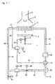
- a gas-heated continuous flow water heater 1 has a heat exchanger 3 which is heated by an atmospheric gas burner 2 and which lies in the region of a combustion chamber 4, which is covered at the top by an exhaust gas collection hood 6 provided with an exhaust gas connection 5.
- the gas burner 2 is fed by a gas line 7, in which a solenoid valve 8 is arranged, which is dominated by a continuously adjusting electromagnet 9, which is actuated via a line 10 by an electronic controller 11.
- the heat exchanger 3 is on the one hand connected to a leading away from a cold water source 12 cold water line 13, which is a series circuit of a trained as rempligelradgeber water flow meter 14 and a flow restrictor 16 inserted, on the other hand leads from the heat exchanger 3 equipped with a temperature sensor 17 hot water tap line 18 off their conclusion is dominated by one or more nozzles 19. Trained as a temperature-dependent resistor temperature sensor 17 is connected via a line 20, the water flow meter 14 via a line 21 to the controller 11.
- a bypass line 24 is inserted, which is a series circuit of a throttle valve 25th , which can be adjusted via a handle 26, between the value "fully closed” and the maximum opening value and a further second flow restrictor 27, which can be preset via an adjusting member 28.
- the two Wasser gutficientbeskyr 16 and 27 are preset such that the water limiter 16 is in series with the heat exchanger 3 is set to about one third of the water flow rate as the lying in the bypass line 24 further Wasser devisficientbeskyr 27.
- the two horizontal curves 32 and 33 connecting the two curves 30 and 31 represent the limiting characteristics, the curve 32 being associated with the flow restrictor 16 and the curve 33 being the sum of the flow restrictor 16 and the flow restrictor 27.
- the points 34 and 35 represent the limited maximum water flow rates through the cable run 13, or at the tapping point 19, the points 36 and 37, the intersections of the curved pieces 32 and 33 with the curve 31. Thus results in a hatched area 38, within the the gas-heated continuous water heater can be operated.
- a water turquoise set of less than 2 I / min is not present, since the start-up water flow rate of the device is below. Operation of the device with smaller throughputs is impossible. Exceeding the point 34 with respect to the water flow rate is not possible because the max. Amount of water is limited by the flow restrictor 16.
- a complete opening of the throttle valve 25 by operating the handle 26 causes an operating point on the curve piece 33 between the points 37 and 35. This means that when opening the throttle valve 25 with minimum device performance of the point 37 can not be driven under, because only at this water flow the device starts. Water flow rates of more than 19 l / min are not achievable, since both flow restrictors 16 and 27 cut off the water flows.
- the hatched field 38 thus results in a field in which a stable and reproducible work of the water heater is possible at preselected water flow rates of the set temperature control.
Landscapes
- Engineering & Computer Science (AREA)
- Physics & Mathematics (AREA)
- Thermal Sciences (AREA)
- Chemical & Material Sciences (AREA)
- Combustion & Propulsion (AREA)
- Mechanical Engineering (AREA)
- General Engineering & Computer Science (AREA)
- Fluid Mechanics (AREA)
- Computer Hardware Design (AREA)
- Instantaneous Water Boilers, Portable Hot-Water Supply Apparatuses, And Control Of Portable Hot-Water Supply Apparatuses (AREA)
- Gas Burners (AREA)
Description
- Die vorliegende Erfindung bezieht sich auf einen gasbeheizten Durchlaufwassererhitzer gemäß dem einleitenden Teil des unabhängigen Patentanspruchs.
- Solche Wasserheizer sind bekanntgeworden durch marktgängige Geräte der Inhaberin. Diese sind so aufgebaut, daß im Wasserweg, kommend vom Kaltwassernetz, zunächst ein sogenannter Wasserschalter, der nach dem Venturi-Prinzip arbeitet und einen Wasserkonstantstromregler enthält, wobei über das Stellglied des Reglers ein Bypass zur Venturi-Düse vorgesehen ist, der von einem einstellbaren Ventil beherrscht ist. Auf den Wasserschalter folgt im Wasserweg der eigentliche Wärmetauscher des Durchlauferhitzers und schließlich das Zapfventil. Der Wärmetauscher ist von einem atmosphärischen Gasbrenner beheizt, der ein mechanisches, durch eine Feder rückstellbares Gasventil aufweist, das von einer Stange des Wasserschalters unmittelbar direkt angetrieben ist, wobei die Stellung der Stange dem Wasserdurchsatz entspricht. Somit wird der Gasdurchsatz dem Kaltwasserdurchsatz nachgeführt. Es handelt sich hier also um eine Gerätetemperatursteuerung. Dem Gasbrenner ist ein Zündbrenner zugeordnet, diesem eine Zündelektrode und eine thermoelektrische Zündsicherung, die ein zweites Ventil aufweist, das mit dem eben erwähnten vom Wasserschalter abhängigen Gasventil in Serie geschaltet ist oder eine elektronische Zündeinrichtung, die bewirkt, daß bei einer Wärmeanforderung das 2. Ventil geöffnet und der Brenner gezündet wird. Beim Öffnen des Zapfventils stellt sich mit dem Öffnungsgrad des Zapfventils ein Wasserdurchsatz ein, dem ein entsprechender Gasdurchsatz nachgeführt wird, so daß der Benutzer Wasser relativ konstanter Temperatur erhält. Der Wasserkonstantstromregler im Wasserschalter hält den Wasserdurchsatz konstant, so daß die Wasserauslauftemperatur eigentlich nur mit dem Gasdruck und der Wassereinlauftemperatur variabel ist. Da diese beiden Größen aber relativ konstant sind, ergeben sich kaum Schwankungen der Wasserauslauftemperatur. Bedingt durch den Bypass im Wasserschalter, ist es möglich, zusätzlich zu dem Wasserdurchsatz durch den Wasserkonstantstromregler einen Bypasswasserdurchsatz zu geben, der nicht die Stellung des Gasventils beeinflußt, der aber durch den Wasserwärmetauscher geleitet wird. Damit ist es möglich, bei Öffnen des Bypasses die Wasserauslauftemperatur zu emiedrigen bzw. bei Schließen des Bypasses zu erhöhen.
- Unabhängig von dem eben beschriebenen Stand der Technik existieren gasbeheizte Durchlaufwasserheizer ohne Wasserschalter und ohne Wasserkonstantstromregler, bei denen am Warmwasserauslauf des Wärmetauschers ein Temperaturfühler außen angeklemmt ist. Dieser Fühler mißt die Temperatur des auslaufenden warmen Wassers und gibt ein entsprechendes Temperatursignal an einen elektronischen Regler, der den aktuellen Temperatur-Istwert des auslaufenden Wassers mit einem einstellbaren Sollwert vergleicht und den Gasdurchsatz entsprechend der festgestellten Regelabweichung variiert. Das Gasventil ist hier als Magnetventil ausgebildet, so daß die Stärke des auf das Magnetventil gegebenen Stroms als Ausgangssignal des Reglers den Gasdurchsatz bestimmt. Der Sollwert der Auslauftemperatur kann durch ein Potentiometer z. B. im Bereich von 40 bis 60° verändert werden. Diese Ausführung weist den Nachteil auf, daß bei einer relativ kleinen eingestellten Temperatur (z. B. nahe 40°) diese im Bereich kleiner Wasserdurchsätze nicht konstant gehalten werden kann, da die vom Brenner abgegebene Wärmeleistung aus Funktionsgründen nicht beliebig verringert werden kann. Wird der sogenannte Überzündgasstrom des Brenners unterschritten, so brennt der Brenner nicht mehr an allen Gas-Luft-Gemisch-Austrittsschlitzen, so daß die Gefahr besteht, daß unverbranntes Gas in den Brennraum gelangt, was zu Explosionen führen kann. Diesem Nachteil wurde dadurch begegnet, daß der Anspringwasserdurchsatz des Gerätes elektronisch an den Sollwert des Wasserdurchsatzes gekoppelt wurde, so daß bei niedrigen vorgewählten Wasserauslauftemperaturen kleine Wasserdurchsätze nicht möglich sind, weil das Gerät nicht anspringt. Ein weiteres Problem ergibt sich bei diesen Geräten auch im Bereich großer Wasserdurchsätze, da die Geräteleistung hier nicht ausreicht, um das Wasser auf den vorgewählten Sollwert zu erhitzen. Es wird zwar der gewünschte Wasserdurchsatz-Sollwert geliefert, aber mit einer der Geräteleistung entsprechenden niedrigen Temperatur.
- Aus der JP 59 097449 A ist ein Durchlauferhitzer mit einem Wasserweg mit Wärmeaustauscher und einem dazu parallelem Bypass bekannt. Mittels eines Temperatursensors stromab der Verbindung des Wasserweges und des Bypasses wird die Auslauftemperatur des Durchlauferhitzers gemessen. In Abhängigkeit dieser gemessenen Temperatur in der Nähe des Zapfventils steuert eine Regelung ein Ventil, welches die Verteilung des Wasserflusses durch den Wasserweg und den Bypasskanal regelt. Dieses Regelventil verbraucht elektrische Energie und unterliegt dem Verschleiß.
- Die nachveröffentlichte EP 990 861 A2 zeigt einen Durchlauferhitzer mit einem Wasserweg mit Wärmeaustauscher und einem dazu parallelem Bypass. In der Bypassleitung befindet sich ein regelbares Drosselventil. Im Wasserweg und in der Bypassleitung befinden sich ferner Durchflussbegrenzer. Ein Temperatursensor erfasst die Temperatur im Wasserweg stromab des Wärmeaustauschers. Bei der Vorrichtung wird die Temperatur an diesem Temperatursensor immer auf den maximalen Sollwert geregelt. Wird eine niedrigere Wassertemperatur als diese hohe Temperatur an der Zapfstelle gewünscht, so soll durch Zumischen von kaltem Wasser durch die Bypassleitung diese Temperatur eingestellt werden. Dies hat zur Folge, dass keine geringen Zapfmengen mit niedriger Auslauftemperatur gezapft werden können. Stets wird das Wasser durch den Wärmeaustauscher in dem Wasserweg auf die maximal zulässige Temperatur erhitzt. Dies bedingt durch die damit verbundenen höheren Abgasverluste einen schlechteren Wirkungsgrad als eine bedarfsgerechte Einstellung der Temperatur hätte.
- Der vorliegenden Erfindung liegt die Aufgabe zugrunde, die geschilderten Nachteile der bekannten Gerätelösungen zu vermeiden.
- Demgemäß ist es Aufgabe der vorliegenden Erfindung, einen gasbeheizten Durchlaufwassererhitzer anzugeben, bei dem es möglich ist, sowohl bei kleinen voreingestellten Wasserdurchsätzen Wasser mit relativ niedriger voreingestellter Auslauftemperatur zu erhalten und bei relativ großen Wasserdurchsätzen die maximal voreinstellbare Auslauftemperatur weitestgehend zu realisieren.
- Die Lösung dieser Aufgabe liegt bei einem gasbeheizten Durchlaufwassererhitzer der eingangs näher bezeichneten Art in den kennzeichnenden Merkmalen des unabhängigen Anspruchs.
- Weitere Ausgestaltungen und besonders vorteilhafte Weiterbildungen der Erfindung ergeben sich aus den abhängigen Ansprüchen sowie aus einem Ausführungsbeispiel der Erfindung, das anschließend anhand der Fig. 1 und 2 der Zeichnung näher erläutert wird.
- Es zeigen:
- Fig. 1
- eine Prinzipdarstellung eines gasbeheizten Durchlaufwassererhitzers und
- Fig. 2
- ein Diagramm.
- In beiden Figuren bedeuten gleiche Bezugszeichen jeweils die gleichen Einzelheiten.
- Ein gasbeheizter Durchlaufwassererhitzer 1 weist einen von einem atmosphärischen Gasbrenner 2 beheizten Wärmetauscher 3 auf, der im Bereich einer Brennkammer 4 liegt, die nach oben durch eine mit einem Abgasstutzen 5 versehene Abgassammelhaube 6 abgedeckt ist.
- Der Gasbrenner 2 wird durch eine Gasleitung 7 gespeist, in der ein Magnetventil 8 angeordnet ist, das von einem stetig verstellenden Elektromagneten 9 beherrscht ist, der über eine Leitung 10 von einem elektronischen Regler 11 betätigbar ist.
- Der Wärmetauscher 3 ist einerseits mit einer von einer Kaltwasserquelle 12 wegführenden Kaltwasserleitung 13 verbunden, der eine Serienschaltung von einem als Flügelradgeber ausgebildeten Wasserdurchsatzgeber 14 und einem Durchflussbegrenzer 16 eingefügt ist, andererseits führt vom Wärmetauscher 3 eine mit einem Temperaturfühler 17 ausgestattete Warmwasserzapfleitung 18 weg, deren Abschluß von einem oder mehreren Zapfventilen 19 beherrscht ist. Der als temperaturabhängiger Widerstand ausgebildete Temperaturfühler 17 ist über eine Leitung 20, der Wasserdurchsatzgeber 14 über eine Leitung 21 mit dem Regler 11 verbunden.
- Die Leitungen 13 und 18 bilden zusammen mit dem Wärmetauscher 3, den Durchflussbegrenzer 16 und den Durchsatzgeber 14 einen Wasserweg 22 durch den gasbeheizten Durchlauferhitzer 1 in Richtung eines Pfeiles 23. In diesen Wasserweg 22 ist eine Bypassleitung 24 eingefügt, die eine Serienschaltung aus einem Drosselventil 25, das über eine Handhabe 26 verstellt werden kann, und zwar zwischen dem Wert "voll geschlossen" und dem maximalen Öffnungswert sowie einem weiteren zweiten Durchflussbegrenzer 27, der über ein Justierglied 28 voreingestellt werden kann. Die beiden Wasserdurchsatzbegrenzer 16 und 27 sind derart voreingestellt, daß der in Serie mit dem Wärmetauscher 3 liegende Wasserbegrenzer 16 auf etwa ein Drittel des Wasserdurchsatzes eingestellt ist wie der in der Bypassleitung 24 liegende weitere Wasserdurchsatzbegrenzer 27. Bezogen auf einen 24-kW-Durchlauferhitzer, ist der Wasserdurchsatzbegrenzer 27 auf einen Durchsatz von 19 l/min eingestellt und der Durchflussbegrenzer 16 auf einen Durchsatz von 6,5 l/min. Für Geräte mit kleineren Leistungen ergeben sich geringe Durchsatzwerte, für Geräte mit größeren Leistungen entsprechend größere Begrenzerdurchsätze. Bei einem 24-kW-Gerät liegt die Gerätemindestleistung, bedingt durch den sogenannten Überzündgasdurchsatz des Brenners 2, bei etwa 30 % der Maximalleistung, d. h., sie liegt bei etwa 8 kW. Diese Verhältnisse liegen bei Geräten mit größerer und kleinerer Leistung analog.
- Die Funktion des eben nach Fig. 1 beschriebenen gasbeheizten Durchlaufwassererhitzers 1 wird nunmehr anhand des Diagramms der Fig. 2 näher erläutert. In der Abszisse der Fig. 2 ist der Wasserdurchsatz in I/min aufskaliert, in der Ordinate die Wasserauslauftemperatur in Grad Celsius. Das Diagramm gilt etwa für ein Gerät mit 24 kW Wärmeleistung. Es sind zwei Kurven 30 und 31 ersichtlich, wobei die Kurve 30 der maximalen Geräteleistung, d. h. der Geräteleistung bei voll geöffnetem Magnetventil 8, und die Kurve 31 der gedrosselten minimalen Geräteleistung entspricht, wenn somit der Überzündgasdurchsatz bei geringstmöglichem einstellbarem Durchlaßquerschnitt des Magnetventils 8 erreicht wird. Die beiden die beiden Kurven 30 und 31 verbindenden waagerecht liegenden Kurvenstücke 32 und 33 stellen die Begrenzerkennlinien dar, wobei die Kurve 32 dem Durchflussbegrenzer 16 und die Kurve 33 der Summe aus Durchflussbegrenzer 16 und Durchflussbegrenzer 27 zugeordnet ist. Die Punkte 34 und 35 stellen die begrenzten maximalen Wasserdurchsätze durch den Leitungszug 13, bzw. an der Zapfstelle 19 dar, die Punkte 36 und 37 die Schnittpunkte der Kurvenstücke 32 und 33 mit der Kurve 31. Somit ergibt sich eine schraffierte Fläche 38, innerhalb der der gasbeheizte Durchlaufwassererhitzer betrieben werden kann.
- Am Sollwertgeber 29 ist ein derartiger Sollwert vorgegeben, daß stets eine Wasserauslauftemperatur in der Zapfleitung 18 mit 60 °C entsteht. Unter der Annahme, daß das Drosselventil 25 sich in Schließstellung befindet, fließt durch die Bypassleitung 24 kein Wasser. Das gesamte Wasser wird somit durch den Wärmetauscher 3 gegeben, sein Durchsatz wird bei Öffnen des Zapfventils 19 vom Durchsatzgeber 14 gemessen. Über den Durchsatz und den am Sollwertgeber 29 eingestellten Temperatursollwert resultiert ein bestimmter Öffnungsgrad für das Magnetventil 8. Somit kann über eine Variation des Öffnungsgrades des Zapfventils 19 das Kurvenstück 32 abgefahren werden. Zwischen einem minimalen Wasserdurchsatz von 2 l/min entsprechend dem Punkt 36 bis zum maximalen Wasserdurchsatz im Punkt 34 von 6,5 l/min. Ein Wasserdurctisatz von weniger als 2 I/min ist nicht darstellbar, da hier der Anspringwasserdurchsatz des Gerätes unterschritten wird. Ein Betrieb des Gerätes mit kleineren Durchsätzen ist unmöglich. Ein Überschreiten des Punktes 34 bezüglich des Wasserdurchsatzes ist nicht möglich, da die max. Wassermenge durch den Durchflussbegrenzer 16 begrenzt wird.
- Ein vollständiges Öffnen des Drosselventils 25 durch Betätigen der Handhabe 26 bewirkt einen Arbeitspunkt auf dem Kurvenstück 33 zwischen den Punkten 37 und 35. Das bedeutet, daß bei Öffnen des Drosselventils 25 bei minimaler Geräteleistung der Punkt 37 nicht unterfahren werden kann, da erst bei diesem Wasserdurchsatz das Gerät überhaupt anspringt. Wasserdurchsätze von mehr als 19 l/min sind nicht erreichbar, da hier beide Durchflussbegrenzer 16 und 27 die Wasserströme abschneiden.
- Durch das schraffierte Feld 38 ergibt sich somit ein Feld, in dem bei vorgewählten Wasserdurchsätzen der eingestellten Temperaturregelung ein stabiles und reproduzierbares Arbeiten des Durchlauferhitzer möglich ist.
- Es ist möglich, im Zuge des Abgasstutzens 5 einen Abgasventilator vorzusehen und bis auf den Lufteinlaß im Bereich des Brenners 2 die Brennkammer 4 technisch gasdicht zu gestalten. Weiterhin ist es möglich, den Begrenzer (27) fortzulassen, wenn nur im Zuge der Bypassleitung 24 ein etwa um das Dreifache bezüglich des Wärmetauschers 3 fließender Wasserdurchsatz sichergestellt ist.
Claims (4)
- Gasbeheizter Durchlaufwassererhitzer (1) mit einer einem von einem Brenner (2) beheizten Wärmetauscher (3), der im Zuge eines von einer Kaltwasserquelle (12) zu einem Zapfventil (19) verlaufenden Wasserweges (22) angeordnet ist, welcher einen Durchflussbegrenzer (16) und einen Durchsatzgeber (14) aufweist, mit dessen Signal ein in einer Gaszuleitung (7) zum Brenner (2) angeordnetes Gasventil (8) verstellt wird sowie mit einer von einem Drosselventil (25) beherrschten Bypassleitung (24) im Wasserweg (22), bei dem die Bypassleitung (24) parallel zu der Reihenschaltung von Durchflussbegrenzer (16) und Wärmetauscher (3) verläuft und einen weiteren Durchflussbegrenzer (27) aufweist, dadurch gekennzeichnet, dass ein einstellbarer Solltemperaturgeber (29) auf den Öffnungsgrad des Gasventils (8) einwirkt.
- Gasbeheizter Durchlaufwassererhitzer nach Anspruch 1, dadurch gekennzeichnet, dass stromab des Wärmetauschers (3) im Wasserweg (22) ein Temperaturfühler (17) vorgesehen ist, welcher auf einen Regler (11) einwirkt, der nach Maßgabe der Istwerte des Durchsatzgebers (14) das Gasventil (8) verstellt.
- Gasbeheizter Durchlaufwassererhitzer nach Anspruch 2, dadurch gekennzeichnet, dass der Regler (11) als elektronischer Regler, der Temperaturfühler (17) als temperaturabhängiger Widerstand und der Durchsatzgeber (14) als Flügelradgeber ausgebildet sind.
- Gasbeheizter Durchlaufwassererhitzer nach Anspruch 1 bis 3, dadurch gekennzeichnet, dass der in Serie mit dem Wärmetauscher (3) im Wasserweg (22) angeordnete Durchflussbegrenzer (16) auf kleinere Werte, vorzugsweise 1/3, voreingestellt ist als der in der Bypassleitung (24) angeordnete weitere Durchflussbegrenzer (27).
Applications Claiming Priority (6)
| Application Number | Priority Date | Filing Date | Title |
|---|---|---|---|
| DE19930236 | 1999-06-25 | ||
| DE19930236 | 1999-06-25 | ||
| DE19932264 | 1999-07-07 | ||
| DE19932264 | 1999-07-07 | ||
| DE19942623 | 1999-08-28 | ||
| DE19942623 | 1999-08-28 |
Publications (3)
| Publication Number | Publication Date |
|---|---|
| EP1063481A2 EP1063481A2 (de) | 2000-12-27 |
| EP1063481A3 EP1063481A3 (de) | 2002-12-04 |
| EP1063481B1 true EP1063481B1 (de) | 2006-01-18 |
Family
ID=27219204
Family Applications (1)
| Application Number | Title | Priority Date | Filing Date |
|---|---|---|---|
| EP00111998A Expired - Lifetime EP1063481B1 (de) | 1999-06-25 | 2000-06-20 | Gasbeheizter Durchlaufwassererhitzer |
Country Status (3)
| Country | Link |
|---|---|
| EP (1) | EP1063481B1 (de) |
| AT (1) | ATE316230T1 (de) |
| DE (2) | DE50012064D1 (de) |
Cited By (3)
| Publication number | Priority date | Publication date | Assignee | Title |
|---|---|---|---|---|
| CN106556151A (zh) * | 2015-09-30 | 2017-04-05 | 青岛经济技术开发区海尔热水器有限公司 | 一种燃气热水器燃气自动增压装置及方法 |
| EP4155620A1 (de) | 2021-09-23 | 2023-03-29 | Pittway Sarl | Wassererhitzer und verfahren zum betreiben eines wassererhitzers |
| EP4219986A1 (de) | 2022-01-31 | 2023-08-02 | Pittway Sarl | 3-wege-fluidventil, vorrichtung zur handhabung eines fluidstroms mit einem 3-wege-ventil und wassererhitzer mit einem 3-wege-ventil und verfahren zu dessen betrieb |
Families Citing this family (6)
| Publication number | Priority date | Publication date | Assignee | Title |
|---|---|---|---|---|
| ITMI20110245A1 (it) * | 2011-02-18 | 2012-08-19 | Grimaldi Stefano | Scalda acqua a gas provvisto di dispositivo anti-spegnimento |
| DE102012003912B3 (de) * | 2012-02-28 | 2013-02-07 | Mertik Maxitrol Gmbh & Co. Kg | Armatur für einen Durchlauf-Wassererhitzer |
| CN105698399A (zh) * | 2016-04-28 | 2016-06-22 | 中国船舶重工集团公司第七一九研究所 | 一种节水型智能热水器 |
| CN107036296A (zh) * | 2017-05-06 | 2017-08-11 | 广东万家乐燃气具有限公司 | 多功能中央燃气热水器及其控制系统 |
| CN108826704A (zh) * | 2018-07-20 | 2018-11-16 | 樱花卫厨(中国)股份有限公司 | 旁通管进水量能够调节的燃气热水器 |
| US12448803B2 (en) * | 2022-08-17 | 2025-10-21 | Copeland Comfort Control Lp | Self-configuring ignition controls |
Family Cites Families (8)
| Publication number | Priority date | Publication date | Assignee | Title |
|---|---|---|---|---|
| US4501261A (en) * | 1982-06-28 | 1985-02-26 | Toto Limited | Instantaneous gas water heater |
| JPS5997449A (ja) * | 1982-11-25 | 1984-06-05 | Matsushita Electric Ind Co Ltd | 加熱制御装置 |
| AT391366B (de) * | 1986-06-23 | 1990-09-25 | Vaillant Gmbh | Durchlauferhitzer |
| DE3805441A1 (de) * | 1987-03-02 | 1988-09-15 | Stiebel Eltron Gmbh & Co Kg | Durchlauferhitzer |
| JPH05272805A (ja) * | 1992-03-25 | 1993-10-22 | Rinnai Corp | 給湯制御装置 |
| DE19735556A1 (de) * | 1997-08-16 | 1999-03-04 | Bosch Gmbh Robert | Vorrichtung zur Brauchwassererwärmung |
| DE19735558A1 (de) * | 1997-08-16 | 1999-02-25 | Bosch Gmbh Robert | Vorrichtung und Verfahren zur Brauchwassererwärmung |
| DE19844856C1 (de) * | 1998-09-30 | 2000-05-18 | Honeywell Bv | Warmwasser-Heizgerät |
-
2000
- 2000-06-20 EP EP00111998A patent/EP1063481B1/de not_active Expired - Lifetime
- 2000-06-20 DE DE50012064T patent/DE50012064D1/de not_active Expired - Fee Related
- 2000-06-20 DE DE10030118A patent/DE10030118A1/de not_active Withdrawn
- 2000-06-20 AT AT00111998T patent/ATE316230T1/de not_active IP Right Cessation
Cited By (6)
| Publication number | Priority date | Publication date | Assignee | Title |
|---|---|---|---|---|
| CN106556151A (zh) * | 2015-09-30 | 2017-04-05 | 青岛经济技术开发区海尔热水器有限公司 | 一种燃气热水器燃气自动增压装置及方法 |
| CN106556151B (zh) * | 2015-09-30 | 2019-10-01 | 青岛经济技术开发区海尔热水器有限公司 | 一种燃气热水器燃气自动增压装置及方法 |
| EP4155620A1 (de) | 2021-09-23 | 2023-03-29 | Pittway Sarl | Wassererhitzer und verfahren zum betreiben eines wassererhitzers |
| WO2023046467A1 (en) | 2021-09-23 | 2023-03-30 | Pittway Sarl | Water heater and methods to operate a water heater |
| EP4219986A1 (de) | 2022-01-31 | 2023-08-02 | Pittway Sarl | 3-wege-fluidventil, vorrichtung zur handhabung eines fluidstroms mit einem 3-wege-ventil und wassererhitzer mit einem 3-wege-ventil und verfahren zu dessen betrieb |
| WO2023143851A1 (en) | 2022-01-31 | 2023-08-03 | Pittway Sarl | 3-way fluid valve, appliance for handling a fluid flow having a 3-way fluid valve and water heater having a 3-way fluid valve and methods to operate the same |
Also Published As
| Publication number | Publication date |
|---|---|
| EP1063481A3 (de) | 2002-12-04 |
| DE10030118A1 (de) | 2000-12-28 |
| DE50012064D1 (de) | 2006-04-06 |
| EP1063481A2 (de) | 2000-12-27 |
| ATE316230T1 (de) | 2006-02-15 |
Similar Documents
| Publication | Publication Date | Title |
|---|---|---|
| EP0644377B1 (de) | Regeleinrichtung für Gasbrenner | |
| DE3707259C2 (de) | Brennervorrichtung | |
| EP0275439B1 (de) | Einrichtung zur Leistungsregelung von brennstoffbefeuerten Wärmeerzeugern | |
| EP0062854B1 (de) | Gasbefeuerter Wasser- oder Lufterhitzer | |
| DE19645180A1 (de) | Druckzerstäuberbrenner für ein motorunabhängiges Fahrzeugheizgerät | |
| EP0505714B1 (de) | Regelvorrichtung für Gasbrenner mit einem Gebläse zum Zuführen von Verbrennungsluft | |
| DE3911268A1 (de) | Regeleinrichtung fuer gasbrenner | |
| DE10030118A1 (de) | Gasbeheizter Durchlaufwassererhitzer | |
| DE19844856C1 (de) | Warmwasser-Heizgerät | |
| DE4440492A1 (de) | Durchlauf-Wassererhitzer | |
| DE2558509C3 (de) | Regeleinrichtung für einen Durchlauferhitzer | |
| DE2728807A1 (de) | Verfahren und vorrichtung zur steuerung des luftdurchsatzes eines gasbeheizten, dichten warmwasserkessels | |
| EP0103303A2 (de) | Brennstoffbeheizte Wärmequelle | |
| DE3721050C2 (de) | ||
| EP0036613A1 (de) | Durch einen Temperaturfühler steuerbare Regeleinrichtung für einen gasbefeuerten Wasser- oder Lufterhitzer | |
| DE3601551C2 (de) | ||
| DE3333606A1 (de) | Brennstoffbeheizte waermequelle | |
| EP0863367B1 (de) | Steuer- und Regelgerät für einen Gasbrenner | |
| EP0036610B1 (de) | Verfahren zum Betreiben einer brennstoffbeheizten Wärmequelle | |
| DE2439779A1 (de) | Durchlauferhitzer | |
| EP0926437A1 (de) | Gasbrenneranordnung für Kochstellen | |
| EP0857916B1 (de) | Verfahren zum Betrieb eines Steuer- und Regelgeräts für einen Brenner | |
| DE3337216C2 (de) | Regelung für eine thermoelektrische Zündsicherung einer brennstoffbeheizten Wärmequelle | |
| DE2950686A1 (de) | Einrichtung zum erwaermen von fluessigkeiten, insbesondere von brauchwasser | |
| DE3132867A1 (de) | Verfahren und schaltungsanordnung zur erzielung eines gleichbleibenden mischungsverhaeltnisses von brennstoff und verbrennungsluft an feuerungseinrichtungen |
Legal Events
| Date | Code | Title | Description |
|---|---|---|---|
| PUAI | Public reference made under article 153(3) epc to a published international application that has entered the european phase |
Free format text: ORIGINAL CODE: 0009012 |
|
| AK | Designated contracting states |
Kind code of ref document: A2 Designated state(s): AT BE CH CY DE DK ES FI FR GB GR IE IT LI LU MC NL PT SE |
|
| AX | Request for extension of the european patent |
Free format text: AL;LT;LV;MK;RO;SI |
|
| RAP1 | Party data changed (applicant data changed or rights of an application transferred) |
Owner name: VAILLANT GMBH |
|
| PUAL | Search report despatched |
Free format text: ORIGINAL CODE: 0009013 |
|
| AK | Designated contracting states |
Kind code of ref document: A3 Designated state(s): AT BE CH CY DE DK ES FI FR GB GR IE IT LI LU MC NL PT SE |
|
| AX | Request for extension of the european patent |
Free format text: AL;LT;LV;MK;RO;SI |
|
| 17P | Request for examination filed |
Effective date: 20030527 |
|
| AKX | Designation fees paid |
Designated state(s): AT BE CH CY DE DK ES FI FR GB GR IE IT LI LU MC NL PT SE |
|
| 17Q | First examination report despatched |
Effective date: 20041111 |
|
| GRAP | Despatch of communication of intention to grant a patent |
Free format text: ORIGINAL CODE: EPIDOSNIGR1 |
|
| GRAC | Information related to communication of intention to grant a patent modified |
Free format text: ORIGINAL CODE: EPIDOSCIGR1 |
|
| GRAS | Grant fee paid |
Free format text: ORIGINAL CODE: EPIDOSNIGR3 |
|
| GRAA | (expected) grant |
Free format text: ORIGINAL CODE: 0009210 |
|
| AK | Designated contracting states |
Kind code of ref document: B1 Designated state(s): AT BE CH CY DE DK ES FI FR GB GR IE IT LI LU MC NL PT SE |
|
| PG25 | Lapsed in a contracting state [announced via postgrant information from national office to epo] |
Ref country code: GB Free format text: LAPSE BECAUSE OF FAILURE TO SUBMIT A TRANSLATION OF THE DESCRIPTION OR TO PAY THE FEE WITHIN THE PRESCRIBED TIME-LIMIT Effective date: 20060118 Ref country code: IE Free format text: LAPSE BECAUSE OF FAILURE TO SUBMIT A TRANSLATION OF THE DESCRIPTION OR TO PAY THE FEE WITHIN THE PRESCRIBED TIME-LIMIT Effective date: 20060118 Ref country code: FI Free format text: LAPSE BECAUSE OF FAILURE TO SUBMIT A TRANSLATION OF THE DESCRIPTION OR TO PAY THE FEE WITHIN THE PRESCRIBED TIME-LIMIT Effective date: 20060118 |
|
| REG | Reference to a national code |
Ref country code: GB Ref legal event code: FG4D Free format text: NOT ENGLISH |
|
| REG | Reference to a national code |
Ref country code: CH Ref legal event code: EP |
|
| REG | Reference to a national code |
Ref country code: IE Ref legal event code: FG4D Free format text: LANGUAGE OF EP DOCUMENT: GERMAN |
|
| REF | Corresponds to: |
Ref document number: 50012064 Country of ref document: DE Date of ref document: 20060406 Kind code of ref document: P |
|
| PG25 | Lapsed in a contracting state [announced via postgrant information from national office to epo] |
Ref country code: DK Free format text: LAPSE BECAUSE OF FAILURE TO SUBMIT A TRANSLATION OF THE DESCRIPTION OR TO PAY THE FEE WITHIN THE PRESCRIBED TIME-LIMIT Effective date: 20060418 Ref country code: SE Free format text: LAPSE BECAUSE OF FAILURE TO SUBMIT A TRANSLATION OF THE DESCRIPTION OR TO PAY THE FEE WITHIN THE PRESCRIBED TIME-LIMIT Effective date: 20060418 |
|
| PG25 | Lapsed in a contracting state [announced via postgrant information from national office to epo] |
Ref country code: ES Free format text: LAPSE BECAUSE OF FAILURE TO SUBMIT A TRANSLATION OF THE DESCRIPTION OR TO PAY THE FEE WITHIN THE PRESCRIBED TIME-LIMIT Effective date: 20060429 |
|
| PG25 | Lapsed in a contracting state [announced via postgrant information from national office to epo] |
Ref country code: PT Free format text: LAPSE BECAUSE OF FAILURE TO SUBMIT A TRANSLATION OF THE DESCRIPTION OR TO PAY THE FEE WITHIN THE PRESCRIBED TIME-LIMIT Effective date: 20060619 |
|
| PG25 | Lapsed in a contracting state [announced via postgrant information from national office to epo] |
Ref country code: CH Free format text: LAPSE BECAUSE OF NON-PAYMENT OF DUE FEES Effective date: 20060630 Ref country code: MC Free format text: LAPSE BECAUSE OF NON-PAYMENT OF DUE FEES Effective date: 20060630 Ref country code: LI Free format text: LAPSE BECAUSE OF NON-PAYMENT OF DUE FEES Effective date: 20060630 |
|
| GBV | Gb: ep patent (uk) treated as always having been void in accordance with gb section 77(7)/1977 [no translation filed] |
Effective date: 20060118 |
|
| REG | Reference to a national code |
Ref country code: IE Ref legal event code: FD4D |
|
| PLBE | No opposition filed within time limit |
Free format text: ORIGINAL CODE: 0009261 |
|
| STAA | Information on the status of an ep patent application or granted ep patent |
Free format text: STATUS: NO OPPOSITION FILED WITHIN TIME LIMIT |
|
| 26N | No opposition filed |
Effective date: 20061019 |
|
| REG | Reference to a national code |
Ref country code: CH Ref legal event code: PL |
|
| EN | Fr: translation not filed | ||
| PG25 | Lapsed in a contracting state [announced via postgrant information from national office to epo] |
Ref country code: AT Free format text: LAPSE BECAUSE OF NON-PAYMENT OF DUE FEES Effective date: 20060620 |
|
| PG25 | Lapsed in a contracting state [announced via postgrant information from national office to epo] |
Ref country code: GR Free format text: LAPSE BECAUSE OF FAILURE TO SUBMIT A TRANSLATION OF THE DESCRIPTION OR TO PAY THE FEE WITHIN THE PRESCRIBED TIME-LIMIT Effective date: 20060419 Ref country code: FR Free format text: LAPSE BECAUSE OF FAILURE TO SUBMIT A TRANSLATION OF THE DESCRIPTION OR TO PAY THE FEE WITHIN THE PRESCRIBED TIME-LIMIT Effective date: 20070309 |
|
| PG25 | Lapsed in a contracting state [announced via postgrant information from national office to epo] |
Ref country code: LU Free format text: LAPSE BECAUSE OF NON-PAYMENT OF DUE FEES Effective date: 20060620 |
|
| PG25 | Lapsed in a contracting state [announced via postgrant information from national office to epo] |
Ref country code: CY Free format text: LAPSE BECAUSE OF FAILURE TO SUBMIT A TRANSLATION OF THE DESCRIPTION OR TO PAY THE FEE WITHIN THE PRESCRIBED TIME-LIMIT Effective date: 20060118 Ref country code: FR Free format text: LAPSE BECAUSE OF FAILURE TO SUBMIT A TRANSLATION OF THE DESCRIPTION OR TO PAY THE FEE WITHIN THE PRESCRIBED TIME-LIMIT Effective date: 20060118 |
|
| PGFP | Annual fee paid to national office [announced via postgrant information from national office to epo] |
Ref country code: IT Payment date: 20090619 Year of fee payment: 10 |
|
| PGFP | Annual fee paid to national office [announced via postgrant information from national office to epo] |
Ref country code: BE Payment date: 20090610 Year of fee payment: 10 |
|
| PGFP | Annual fee paid to national office [announced via postgrant information from national office to epo] |
Ref country code: DE Payment date: 20090420 Year of fee payment: 10 |
|
| PGFP | Annual fee paid to national office [announced via postgrant information from national office to epo] |
Ref country code: NL Payment date: 20100308 Year of fee payment: 11 |
|
| BERE | Be: lapsed |
Owner name: *VAILLANT G.M.B.H. Effective date: 20100630 |
|
| PG25 | Lapsed in a contracting state [announced via postgrant information from national office to epo] |
Ref country code: IT Free format text: LAPSE BECAUSE OF NON-PAYMENT OF DUE FEES Effective date: 20100620 |
|
| PG25 | Lapsed in a contracting state [announced via postgrant information from national office to epo] |
Ref country code: DE Free format text: LAPSE BECAUSE OF NON-PAYMENT OF DUE FEES Effective date: 20110101 |
|
| PG25 | Lapsed in a contracting state [announced via postgrant information from national office to epo] |
Ref country code: BE Free format text: LAPSE BECAUSE OF NON-PAYMENT OF DUE FEES Effective date: 20100630 |
|
| REG | Reference to a national code |
Ref country code: NL Ref legal event code: V1 Effective date: 20120101 |
|
| PG25 | Lapsed in a contracting state [announced via postgrant information from national office to epo] |
Ref country code: NL Free format text: LAPSE BECAUSE OF NON-PAYMENT OF DUE FEES Effective date: 20120101 |