EP0036613A1 - Durch einen Temperaturfühler steuerbare Regeleinrichtung für einen gasbefeuerten Wasser- oder Lufterhitzer - Google Patents
Durch einen Temperaturfühler steuerbare Regeleinrichtung für einen gasbefeuerten Wasser- oder Lufterhitzer Download PDFInfo
- Publication number
- EP0036613A1 EP0036613A1 EP81101973A EP81101973A EP0036613A1 EP 0036613 A1 EP0036613 A1 EP 0036613A1 EP 81101973 A EP81101973 A EP 81101973A EP 81101973 A EP81101973 A EP 81101973A EP 0036613 A1 EP0036613 A1 EP 0036613A1
- Authority
- EP
- European Patent Office
- Prior art keywords
- air
- gas
- control valve
- control device
- valve
- Prior art date
- Legal status (The legal status is an assumption and is not a legal conclusion. Google has not performed a legal analysis and makes no representation as to the accuracy of the status listed.)
- Granted
Links
- XLYOFNOQVPJJNP-UHFFFAOYSA-N water Substances O XLYOFNOQVPJJNP-UHFFFAOYSA-N 0.000 title claims abstract description 6
- 230000033228 biological regulation Effects 0.000 title description 2
- 238000002485 combustion reaction Methods 0.000 claims abstract description 27
- 239000007789 gas Substances 0.000 claims description 79
- 239000012528 membrane Substances 0.000 claims description 8
- 238000010438 heat treatment Methods 0.000 claims description 6
- 230000005284 excitation Effects 0.000 claims description 4
- 238000004804 winding Methods 0.000 claims description 3
- UGFAIRIUMAVXCW-UHFFFAOYSA-N Carbon monoxide Chemical compound [O+]#[C-] UGFAIRIUMAVXCW-UHFFFAOYSA-N 0.000 claims description 2
- 239000003546 flue gas Substances 0.000 claims description 2
- 230000001105 regulatory effect Effects 0.000 abstract description 4
- 239000000446 fuel Substances 0.000 description 6
- 230000000694 effects Effects 0.000 description 5
- VNWKTOKETHGBQD-UHFFFAOYSA-N methane Chemical compound C VNWKTOKETHGBQD-UHFFFAOYSA-N 0.000 description 4
- 239000000203 mixture Substances 0.000 description 3
- 238000011144 upstream manufacturing Methods 0.000 description 3
- 230000001276 controlling effect Effects 0.000 description 2
- 230000003111 delayed effect Effects 0.000 description 2
- 239000003345 natural gas Substances 0.000 description 2
- 238000007664 blowing Methods 0.000 description 1
- 238000006243 chemical reaction Methods 0.000 description 1
- 239000000567 combustion gas Substances 0.000 description 1
- 230000007423 decrease Effects 0.000 description 1
- 230000001934 delay Effects 0.000 description 1
- 239000002737 fuel gas Substances 0.000 description 1
- 238000002789 length control Methods 0.000 description 1
- 238000004519 manufacturing process Methods 0.000 description 1
- 239000000463 material Substances 0.000 description 1
- 238000012544 monitoring process Methods 0.000 description 1
- 238000000926 separation method Methods 0.000 description 1
- 230000001360 synchronised effect Effects 0.000 description 1
Images

Classifications
-
- F—MECHANICAL ENGINEERING; LIGHTING; HEATING; WEAPONS; BLASTING
- F23—COMBUSTION APPARATUS; COMBUSTION PROCESSES
- F23N—REGULATING OR CONTROLLING COMBUSTION
- F23N5/00—Systems for controlling combustion
- F23N5/02—Systems for controlling combustion using devices responsive to thermal changes or to thermal expansion of a medium
- F23N5/025—Systems for controlling combustion using devices responsive to thermal changes or to thermal expansion of a medium using electrical or electromechanical means
-
- F—MECHANICAL ENGINEERING; LIGHTING; HEATING; WEAPONS; BLASTING
- F23—COMBUSTION APPARATUS; COMBUSTION PROCESSES
- F23N—REGULATING OR CONTROLLING COMBUSTION
- F23N1/00—Regulating fuel supply
- F23N1/02—Regulating fuel supply conjointly with air supply
- F23N1/025—Regulating fuel supply conjointly with air supply using electrical or electromechanical means
-
- F—MECHANICAL ENGINEERING; LIGHTING; HEATING; WEAPONS; BLASTING
- F23—COMBUSTION APPARATUS; COMBUSTION PROCESSES
- F23N—REGULATING OR CONTROLLING COMBUSTION
- F23N1/00—Regulating fuel supply
- F23N1/02—Regulating fuel supply conjointly with air supply
- F23N1/027—Regulating fuel supply conjointly with air supply using mechanical means
-
- F—MECHANICAL ENGINEERING; LIGHTING; HEATING; WEAPONS; BLASTING
- F23—COMBUSTION APPARATUS; COMBUSTION PROCESSES
- F23N—REGULATING OR CONTROLLING COMBUSTION
- F23N2235/00—Valves, nozzles or pumps
- F23N2235/02—Air or combustion gas valves or dampers
- F23N2235/06—Air or combustion gas valves or dampers at the air intake
-
- F—MECHANICAL ENGINEERING; LIGHTING; HEATING; WEAPONS; BLASTING
- F23—COMBUSTION APPARATUS; COMBUSTION PROCESSES
- F23N—REGULATING OR CONTROLLING COMBUSTION
- F23N2235/00—Valves, nozzles or pumps
- F23N2235/12—Fuel valves
- F23N2235/20—Membrane valves
-
- F—MECHANICAL ENGINEERING; LIGHTING; HEATING; WEAPONS; BLASTING
- F23—COMBUSTION APPARATUS; COMBUSTION PROCESSES
- F23N—REGULATING OR CONTROLLING COMBUSTION
- F23N2237/00—Controlling
- F23N2237/16—Controlling secondary air
Definitions
- the invention relates to a control device according to the preamble of claim 1, as is known for example from GB-PS 12 35 891.
- a control device for optimal use of the fuel supplied to a burner, not only must the fuel supply be regulated as a function of the required heat, but also the combustion air supply must be adapted to the respective fuel quantity in order to achieve optimal combustion.
- a spring-loaded diaphragm drive is connected to the outlet line leading to the burner of a gas control valve controlled by the temperature sensor and controls an air flap in the combustion air supply duct. The more gas that is fed to the burner, the more the flap opens, thereby increasing the amount of combustion air supplied by a fan.
- said membrane drive controls the speed of the blower motor via a brake and in this way the combustion air supply.
- a device for controlling the supply of gas and air to an infrared burner in which an air flap is installed in the combustion air duct.
- this is influenced by a pressure regulator that keeps the pressure in the duct constant, and on the other hand it is controlled by one acted upon by a temperature sensor controlled servo motor.
- the air flows through an orifice into a mixing chamber, to which the fuel gas is also fed via a nozzle.
- the aim is that the air pressure upstream of the orifice and the gas pressure upstream of the nozzle are the same.
- the air duct is connected via a branch line to the control chamber of a constant pressure regulator, which influences a valve which is switched into the gas line.
- the object of the invention is to create a reliable control device that works as quickly as possible with little effort, which controls both the gas quantity and the air quantity in the same direction for the purpose of achieving optimal combustion and can be largely implemented with conventional components.
- This object is achieved by the invention characterized in claim 1.
- a common servo pressure regulator acts directly on the gas control valve and the air volume control element, so that both flows are regulated in the same direction and without delay.
- the use of a servo pressure regulator has the advantage that if the supply gas pressure fails, the main gas valve closes automatically under the influence of its closing spring and thus blocks and keeps the gas path blocked.
- a device for mixing gas and air for generating a heating gas in which the gas comes under driving pressure to a jet pump, which is equipped with an air intake and a Venturi tube for mixing the air with the gas.
- the venturi tube opens into a mixing chamber.
- a second jet pump is also provided, the input of which is connected to a compressed air generator and which also conveys an additional air quantity into the mixing chamber.
- the mixing chamber is provided with heating gas outlet connections which lead into a gas supply network.
- the amount of air sucked in can be adjusted manually by means of an air flap arranged in the intake port. Since a city gas network is supplied with a heating gas / air mixture from the common mixing chamber, from which only a uniform composition is required, without an adjustment to different quantities is required a common regulation of both jet pumps is neither provided nor necessary here.
- the invention is also concerned with the task of achieving a simultaneous control of gas supply and combustion air supply in water or air heaters with gas supply via an injector nozzle which simultaneously sucks in combustion air, in such a way that gas supply and combustion air supply are controlled in such a way that even with changing heat requirements and thus changing fuel supply always the optimal fuel / air mixture is fed to the burner.
- This additional object is achieved by the features of claim 5.
- a servo pressure regulator is used, with the additional advantage that only relatively small gas or suction air flows can be processed by both the gas control valve and the air volume control element, while the primary air and most of the secondary air are sucked by the injector nozzles (Venturi nozzles) to the burner is forwarded. It is also particularly advantageous that when the burner is switched off there is almost no draft due to the closed housing, and the heat present in the burner does not escape through the chimney. Together with the optimal combustion, this leads to further energy savings.
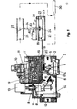
- the gas control device essentially has the structure known from the company publication D3H-29 HONEYWELL "compact valves V4600 / V8600", an embodiment known from DE-PS 26 46 31o being used as the servo pressure regulator.
- the closing body 1 of the main gas valve is spring-loaded in the closing direction by a closing spring 2 and is lifted off the seat by a diaphragm drive when the force exerted on the diaphragm 4 by the control pressure in the chamber 3 exerts the force exerted by the outlet pressure in the outlet 5 on the opposite side of the diaphragm 4 Force plus the force of spring 2 exceeds.
- the drive chamber 3 receives its control pressure via a channel 6 and a solenoid 7 with closing body 8 from the output chamber 9 of a servo pressure regulator 10. This is controlled by a temperature sensor 11, as described in detail in DE-PS 26 46 310. If the outlet pressure in the outlet 5 decreases, the pressure in the chamber 9 and thus also the drive chamber 3 increases, as a result of which the membrane 4 moves the closing body 1 against the force of the spring 2 in the opening direction and thus the gas flow from the inlet 12 to the outlet 5 enlarged.
- the ignition safety device shown in the left part of the drawing with the on button 13, the solenoid insert 14, the safety valve 15 and the pilot burner valve 16 is known from DE-OS 26 05 128 and is of no importance in connection with the present invention.
- the inlet pressure is fed to the pressure regulator 10 via the channel 17 and a throttle point 18, so that the same control pressure builds up behind the throttle point 18 in the space 19 as in the chamber 9.
- the chambers 9 and 19 are above the on-off valve 8 which is open in the operating state shown in connection.
- a second diaphragm drive 21 is connected to the chamber 19 via a line 20 and can optionally be structurally combined with the gas control device. Below its membrane 22, the same servo control pressure prevails in the chamber 23 as in the "r '* drive chamber 3 of the membrane drive for the main gas valve 1.
- the drive rod 24 of an air quantity actuator is present on the membrane 22, which in the exemplary embodiment shown is provided by a throttle valve 25 in the air supply channel 26 is shown.
- a spring 27 abuts a collar 28 of the drive rod on the one hand and is fastened to the drive housing 21 on the other side. Their force counteracts the force exerted by the pressure in the chamber 23.
- the tension of the spring 27 can thus be set the characteristic of the air damper actuator 21. In this way, a desired gas / air ratio can be specified.
- the gas passes and from the air duct 26 the Ver Combustion air to the burner 30.4
- the arrangement is such that, with an increasing amount of gas at the outlet 5 of the gas control device, the amount of air let through by the throttle valve 25 through the air duct 26 to the burner 30 also increases.
- the solenoid valve 7,8 switches over and thus blocks the connection between the chambers 9 and 19, so that the connection of the diaphragm drive 21 to the chamber 19 is advantageous insofar as its separation from the chamber 9 at Closing the valve 8, the closing time of the main valve 1 is not delayed by the additional volume of the drive chamber 23. The latter is rather separated from the volume of the chamber 3, so that the pressure therein can be quickly reduced via the channel 6, the valve 8 and the channel 81 to the outlet side and the main gas valve 1 closes.
- this type of connection of the diaphragm actuator 21 has the advantage that when the main gas valve 1 is closed, the throttle valve 25 goes into its fully open position.
- the drive chamber 23 is now namely supplied via the channel 17 and the throttle point 18 and the channel 20 to the full input pressure without the pressure regulator 10 blowing off part of the same towards the outlet.
- a snap switch 82 is also actuated by the drive rod 24, the contact of which is connected in series with the excitation winding of the solenoid valve 7. As soon as the air flap 25 is closed, this contact interrupts the power supply to the excitation winding of the solenoid valve 7. The position of the throttle valve 25 is thus checked before the burner is started.
- the gas control device can only be started via the solenoid valve 17 when the throttle valve is fully open and the switch 82 is thus closed.
- the switch 82 is actuated via a switching lever 84 which bears against a collar 83 of the drive rod 24. If necessary, further diaphragm drives can be connected to the chamber 19 or the channel 20, for example for closing the chimney when the burner is switched off.
- the second exemplary embodiment corresponding to FIGS. 2 and 3 also uses a servo pressure regulator as described in DE-PS 26 46 310 and DE-OS 29 03 201.
- a servo pressure regulator as described in DE-PS 26 46 310 and DE-OS 29 03 201.
- other servo pressure regulators can also be used.
- the gas control valve has the same structure as in FIG. 1.
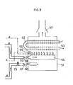
- FIG. 2 shows the gas valve including the servo pressure regulator and the air control valve with an upstream fan
- FIG. 3 shows a gas-fired heating boiler as a consumer, for example for a central heating system.
- the drive chamber 31 of a second servo pressure-controlled air control valve 32 is connected here via a line 20 to the chamber 19 of the servo pressure regulator.
- the closing body 33 is supported by the membrane 35 via a pin 34 and is biased in the closing direction by a spring 36.
- the inlet 37 of the air control valve is connected to a compressed air generator in the form of a fan 38, while the sensor 40 of a flow switch 41 is arranged in the outlet 30. Its normally open contact, which is closed by the air flow, lies in the excitation circuit of the closing solenoid valve 4.
- Fig. 3 shows as a consumer a heat exchanger 52 surrounded by a closed housing 51, the heated one Water passes through outlet 53 to one or more radiators.
- a main burner 54 heats the heat exchanger 52, a pilot burner 55 being connected to the pilot burner connection 65 of the gas control device and a thermocouple 56 monitoring the pilot flame to the magnet insert 14 of the ignition safety device.
- the combustion gases leave the housing 51 through an exhaust 57.
- the inlet 58 of the main burner 54 is opposed by an injector nozzle 59, via which gas flows into the main burner from the outlet 5 of the gas control valve. Due to the jet effect of the nozzle 59, the gas flow simultaneously draws in primary air, which is fed to the main burner 54 as combustion air.
- the housing 51 has an inlet 60 for secondary air, which is opposed by a further injector nozzle 61. It is fed with compressed air by the air control valve 32 and, due to its jet effect, also draws in additional combustion air and presses it into the interior of the housing 51, where it is available to the main burner 54 in order to achieve the most complete possible combustion. Otherwise the housing 51 is closed.
- the arrangement is such that as the amount of gas at the outlet 5 of the gas control device increases, the amount of compressed air let through by the air control valve 32 also increases, and because of the jet effect of the two nozzles 59 and 61, as much primary and secondary air is fed to the main burner 54 as to one complete and optimal combustion of the amount of gas supplied is required.
- the amount of gas let through from the gas control valve to the nozzle 59 is regulated with the aid of the servo pressure regulator 10 as a function of the temperature monitored with the aid of the temperature sensor 11.
- the solenoid valve 7, 8 switches over and thus blocks the connection between the chambers 9 and 19, so it turns out that the connection of the air control valve 32 to the chamber 19 is advantageous in that, by separating it from the chamber 9 when Closing the valve 8, the closing time of the main valve is not delayed by the additional volume of the drive chamber 31. The latter is rather separated from the volume of the chamber 3, so that the pressure therein can be quickly reduced via the channel 6, the valve 8 and the channel 26 to the outlet side and the main gas valve 1 closes.
- the inlet opening 60 is significantly smaller than the secondary air slots of conventional boilers, because the main part of the secondary air is sucked in by the jet effect of the air nozzle 61. If this jet effect ceases to exist, only an insignificant amount of air flows through the inlet 60.
- a modified embodiment is shown in broken lines in FIG. 2, in which the air control valve 32 is omitted and instead a pneumatic-electrical converter 42 is connected to the control air line 20. It is fed, for example, with alternating mains voltage and supplies at its output a direct current for the drive motor 43 of the blower 38 that is proportional to the pneumatic input signal in terms of its current intensity.
- the blower speed and thus the speed of the blower 38 also increase Air volume to, which results in a synchronous gas and air volume control.
- the conversion of the pneumatic input signal of the converter 42 into a signal controlling the motor speed can be carried out in a known manner with the aid of a phase control or a pulse length control.
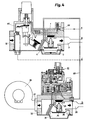
- FIG. 4 Another embodiment of the invention results if the boiler 51 according to FIG. 3 is connected to the control device according to FIG. 4.
- the servo pressure controller 10 does not act on the gas control device 67, but rather on the air control valve 72. The amount of gas is thus tracked to the amount of air supplied. It applies to both embodiments according to FIGS. 2 and 4 that a possible leak in line 20 results in the gas valve and the air valve being closed, so that the arrangement is intrinsically safe in this respect.
- the embodiment according to FIG. 4 also has the advantage that the servo pressure regulator does not work with gas but with air and consequently no gas can escape in the event of any leaks. This makes it possible to manufacture the servo pressure regulator from less demanding materials, for example from plastic. The same applies to the air control valve in both cases.
- Another advantage of the arrangement according to FIG. 4 is that the flow switch 40, 41 can be dispensed with. In this embodiment, the gas valve 67 can only open when the fan 38 is in operation and thus an air flow is present.
- An adjustable throttle 73 which is arranged between the air control valve 32 or 72 on the one hand and the further injector nozzle 61 on the other hand, enables the setting of a desired gas / air ratio and thus an air excess sufficient for good combustion.
- the compressed air source 38 only has to deliver a relatively small amount of air.
- the fan 38 would have to convey about 10m 3 of air.
- the blower 38 itself only has to deliver about 0.5 m 3 . It is also advantageous that fluctuations in the supply pressure are not only corrected for the gas supply, but this also applies equally to the air supply.
Landscapes
- Engineering & Computer Science (AREA)
- Chemical & Material Sciences (AREA)
- Combustion & Propulsion (AREA)
- Mechanical Engineering (AREA)
- General Engineering & Computer Science (AREA)
- Regulation And Control Of Combustion (AREA)
Abstract
Description
- Die Erfindung betrifft eine Regeleinrichtung gemäß Gattungsbegriff des Anspruchs 1, wie sie beispielsweise aus GB-PS 12 35 891 bekannt ist. Zur optimalen Ausnutzung des einem Brenner zugeführten Brennstoffs muß nicht nur die Brennstoffzufuhr in Abhängigkeit vom benötigten Wärmebedarf geregelt, sondern zwecks Erzielung einer optimalen Verbrennung auch die Verbrennungsluftzufuhr der jeweiligen Brennstoffmenge angepaßt werden. In der genannten GB-PS ist deshalb an die zum Brenner führende Ausgangsleitung eines vom Temperaturfühler gesteuerten Gasregelventils ein federbelasteter Membranantrieb angeschlossen, der eine Luftklappe im Verbrennungsluftzufuhrkanal steuert. Je mehr Gas dem Brenner zugeleitet wird, um so weiter öffnet die Klappe und erhöht damit die über ein Gebläse zugeführte Verbrennungsluftmenge. Nach einer weiteren Ausführungsform dieser bekannten Regeleinrichtung steuert der genannte Membranantrieb über eine Bremse die Drehzahl des Gebläsemotors und auf diese Weise die Verbrennungsluftzufuhr.
- Weiterhin ist aus DE-OS 15 29 184 eine Vorrichtung zur Steuerung der Zufuhr von Gas und Luft zu einem Infrarotbrenner bekannt, bei der in den Verbrennungsluftkanal eine Luftklappe eingebaut ist. Diese steht einerseits unter dem Einfluss eines den Druck im Kanal konstanthaltenden Druckreglers und wird andererseits von einem durch einen Temperaturfühler gesteuerten Servomotor beaufschlagt. Die Luft strömt über eine Blende in eine Mischkammer,der über eine Düse zugleich das Brenngas zugeführt wird. Angestrebt wird, daß der Luftdruck stromaufwärts der Blende und der Gasdruck stromaufwärts der Düse gleich groß sind. Zu diesem Zweck ist der Luftkanal über eine Stichleitung mit der Steuerkammer eines-Gleichdruckreglers verbunden, welcher ein in die Gasleitung eingeschaltetes Ventil beeinflußt.
- Während bei der Anordnung nach GB-PS 12 35 891 der dem Brenner zugeführte Gasdruck als Führungsgröße für die zuzuführende Luftmenge dient, erfolgt bei DE-OS 15 29 184 umgekehrt die Gasregelung in Abhängigkeit vom Druck in der Luftzuleitung. In beiden Fällen wirkt der vom Temperaturfühler gesteuerte Regler nur auf eine der beiden Größen unmittelbar ein, während die andere nachgeführt wird. Dies kann zu Verzögerungen und Instabilitäten der Regeleinrichtung führen.
- Aufgabe der Erfindung ist es, mit geringem Aufwand eine zuverlässige und möglichst verzögerungsfrei arbeitende Regeleinrichtung zu schaffen, welche sowohl die Gasmenge als auch die Luftmenge gleichsinnig zwecks Erzielung einer optimalen Verbrennung regelt und weitgehend mit herkömmlichen Komponenten realisierbar ist. Diese Aufgabe wird gelöst durch die im Anspruch 1 gekennzeichnete Erfindung. Ein gemeinsamer Servodruckregler wirkt unmittelbar auf das Gasregelventil und das Luftmengenstellglied ein, so daß beide Ströme gleichsinnig und ohne Verzögerung geregelt werden. Die Verwendung eines Servodruckreglers hat den Vorteil, daß bei Ausfall des Versorgungsgasdrucks das Hauptgasventil selbsttätig unter dem Einfluss seiner Schließfeder schließt und somit den Gasweg sperrt und gesperrt hält.
- Es ist bekannt, daß zur optimalen Verbrennung von 1m3 Erdgas etwa 10M 3 Verbrennungslufterforderlich sind. Bei herkömmlichenWassererhitzern verwendet man für die Zufuhr von Gas und Verbrennungsluft eine an die Gaszufuhrleitung angeschlossene in den Brenner mündende Injektordüse, deren Gasstrom gleichzeitig einen entsprechenden Luftstrom ansaugt und dem Brenner zuführt. Dabei bleibt das Gas/Luftverhältnis auch bei sich ändernder Gaszufuhr etwa gleich und zwar bei 1:6. Damit werden durch diese Primärluftansaugung nur etwa 60% der erforderlichen Verbrennungsluft zugeführt. Somit muß eine zusätzliche sekundäre Luftzufuhr die restlichen 40% Verbrennungsluft bereitstellen. Zu diesem Zweck sieht man bisher im Gehäuse des Brenners zusätzliche Luftansauglöcher vor, deren Größe dem maximalen Brennstoffdurchsatz angepaßt ist. Dies bedeutet aber, daß bei geringer Gaszufuhr ein beträchtlicher Luftüberschuß vorhanden ist und folglich der Wirkungsgrad der Verbrennung stark absinkt.
- Aus DE-OS 22 51 994 ist eine Vorrichtung zum Mischen von Gas und Luft zur Erzeugung eines Heizgases bekannt, bei der das Gas unter Treibdruck zu einer Strahlpumpe gelangt, mit welche einem Luftansaugstutzen sowie einem Venturirohr zum Mischen der Luft mit dem Gas ausgestattet ist. Das Venturirohr mündet in eine Mischkammer. Dabei ist noch eine zweite Strahlpumpe vorgesehen, deren Eingang an einen Drucklufterzeuger angeschlossen ist und welche eine Zusatzluftmenge ebenfalls in die Mischkammer befördert. Die Mischkammer ihrerseits ist mit Heizgasaustrittsstutzen versehen, welche in ein Gasversorgungsnetz führen. Bei beiden Strahlpumpen läßt sich die angesaugte Luftmenge mittels einer im Ansaugstutzen angeordneten Luftklappe von Hand verstellen. Da aus der gemeinsamen Mischkammer ein Stadtgasnetz mit einem Heizgas/Luftgemisch versorgt wird, von dem lediglich eine gleichmäßige Zusammensetzung verlangt wird, ohne eine An passung an unterschiedliche Mengen zu benötigen, ist hier eine gemeinsame Regelung beider Strahlpumpen weder vorgesehen noch erforderlich.
- Die Erfindung befaßt sich zusätzlich mit der Aufgabe auch bei Wasser- oder Lufterhitzern mit Gasversorgung über eine zugleich Verbrennungsluft ansaugende Injektordüse mit möglichst wirtschaftlichen Mitteln eine gleichzeitige Regelung von Gaszufuhr und Verbrennungsluftzufuhr zu erzielen, derart, daß auch bei sich änderndem Wärmebedarf und damit sich ändernder Brennstoffzufuhr stets das optimale Brennstoff/Luftgemisch dem Brenner zugeleitet wird. Diese zusätzliche Aufgabe wird durch die Merkmale des Anspruchs 5 gelöst. Wiederum findet ein Servodruckregler Verwendung, wobei zusätzlich der Vorteil erreicht wird, daß sowohl vom Gasregelventil als vom Luftmengenstelleglied nur verhältnismäßig geringe Gas- bzw.Saugluftströme zu verarbeiten sind, während die Primärluft sowie der größte Teil der Sekundärluft durch Saugwirkung der Injektordüsen (Venturidüsen) dem Brenner zugeleitet wird. Von besonderem Vorteil ist darüberhinaus, daß bei abgeschaltetem Brenner infolge des geschlossenen Gehäuses fast kein Zug vorhanden ist, und somit die im Brenner vorhandene Wärme nicht durch den Schornstein entweicht. Dies führt zusammen mit der optimalen Verbrennung zu einer weiteren Energieersparnis.
- Vorteilhafte Ausgestaltungen der Erfindung ergeben sich aus den Unteransprüchen. Sie wird nachfolgend anhand einiger Ausführungsbeispiele erläutert. Dabei zeigt:
- Fig. eine erste Ausführungsform mit einem von einem Servodruckregler gesteuerten Gasregelventil und einem an den Druckregler angeschlossenen Membranantrieb für das Luftmengenstellglied in Form einer Drosselklappe;
- die Figuren 2 und 3 zusammen eine Ausführungsform, bei der der Servodruckregler wiederum auf ein Gasregelgerät aufgesetzt und das zusätzliche Sekundärluftventil über eine Leitung an den Servodruckregler angeschlossen ist;
- die Figuren 4 und 3 zusammen ein Ausführungsbeispiel, bei dem der Servodruckregler auf das Luftventil aufgesetzt und das Gasregelgerät über eine Leitung an den Druckregler angeschlossen ist.
- Bei der Ausführungsform nach Figur 1 hat das Gasregelgerät im wesentlichen den aus der Firmendruckschrift D3H-29 HONEYWELL "Kompakt-Ventile V4600/V8600" bekannten Aufbau, wobei als Servodruckregler eine aus DE-PS 26 46 31o bekannte Ausführungsform dient. Der Schließkörper 1 des Hauptgasventils ist durch eine Schließfeder 2 in Schließrichtung federbelastet und wird durch einen Membranantrieb vom Sitz,abgehoben, wenn die vom Steuerdruck in der Kammer 3 auf die Membran 4 ausgeübte Kraft die vom Ausgangsdruck im Auslaß 5 auf die Gegenseite der Membran 4 ausgeübte Kraft zuzüglich der Kraft der Feder 2 übersteigt. Die Antriebskammer 3 erhält ihren Steuerdruck über einen Kanal 6 und ein Einschaltmagnetventil 7 mit Schließkörper 8 von der Ausgangskammer 9 eines Servodruckreglers 10. Dieser wird, wie in DE-PS 26 46 310 ausführlich beschrieben ist, von einem Temperaturfühler 11 gesteuert. Nimmt der Ausgangsdruck im Auslaß 5 ab, so erhöht sich der Druck in der Kammer 9 und damit auch der Antriebskammer 3, wodurch die Membran 4 den Schließkörper 1 gegen die Kraft der Feder 2 in öffnungsrichtung verschiebt und damit den Gasstrom vom Einlaß 12 zum Auslaß 5 vergrößert. Die im linken Teil der Zeichnung dargestellte Zündsicherungseinrichtung mit Einschalttaste 13, Elektromagneteinsatz 14, Sicherheitsventil 15 und Zündbrennerventil 16 ist aus DE-OS 26 05 128 bekannt und im Zusammenhang mit der vorliegenden Erfindung ohne Bedeutung. Der Eingangsdruck wird dem Druckregler 10 über den Kanal 17 und eine Drosselstelle 18 zugeführt, so daß sich hinter der Drosselstelle 18 im Raum 19 der gleiche Steuerdruck aufbaut, wie in der Kammer 9. Die Kammern9 und 19 stehen über das im gezeigten Betriebszustand offene Einschaltventil 8 in Verbindung.
- An die Kammer 19 ist über eine Leitung 20 ein zweiter Membranantrieb 21 angeschlossen, der gegebenenfalls mit dem Gasregelgerät konstruktiv vereinigt sein kann. Unterhalb seiner Membran 22 herrscht in der Kammer 23 der gleiche Servosteuerdruck wie in de»r'*Antriebskammer 3 des Membranantriebs für das Hauptgasventil 1. An der Membran 22 liegt die Antriebsstange 24 eines Luftmengenstellgliedes an, welches im gezeigten Ausführungsbeispiel durch eine Drosselklappe 25 im Luftzufuhrkanal 26 dargestellt ist. Eine Feder 27 liegt einerseits an einem Bund 28 der Antriebsstange an und ist auf der anderen Seite am Antriebsgehäuse 21 befestigt. Ihre Kraft wirkt der vom Druck in der Kammer 23 ausgeübten Kraft entgegen. Mittels einer im Gehäuse verstellbaren Einstellschraube 29 kann die Spannung der Feder 27 damit die Kennlinie des Luftklappenantriebs 21 eingestellt werden. Auf diese Weise läßt sich ein gewünschtes Gas/Luftverhältnis vorgeben. Vom Auslaß 5 des Gasregelgerätes gelangt das Gas und vom Luftkanal 26 die Verbrennungsluft zum Brenner 30.4 Die Anordnung ist so getroffen, daß mit zunehmender Gasmenge am Auslaß 5 des Gasregelgerätes auch die von der Drosselklappe 25 durch den Luftkanal 26 zum Brenner 30 hindurchgelassene Luftmenge zunimmt. Schaltet bei fehlendem Wärmebedarf das Magnetventil 7,8 um und sperrt damit die Verbindung zwischen den Kammern 9 und 19, so zeigt sich, daß der Anschluß des Membrantriebs 21 an die Kammer 19 insofern von Vorteil ist, als durch deren Trennung von der Kammer 9 beim Schließen des Ventils 8 die Schließzeit des Hauptventils 1 nicht durch das zusätzliche Volumen der Antriebskammer 23 verzögert wird. Letztere ist vielmehr vom Volumen der Kammer 3 getrennt, so daß der darin herrschende Druck schnell über den Kanal 6,das Ventil 8 und den Kanal 81 zur Auslaßseite hin abgebaut werden kann und das Hauptgasventil 1 schließt. Außerdem hat diese Art des Anschlusses des Membranantriebs 21 den Vorteil, daß bei geschlossenem Hauptgasventil 1 die Drosselklappe 25 in ihre voll geöffnete Stellung geht. Der Antriebskammer 23 wird jetzt nämlich über den Kanal 17 und die Drosselstelle 18 sowie den Kanal 20 der volle Eingangsdruck zugeleitet, ohne daß der Druckregler 10 einen Teil desselben zum Auslaß hin abbläst.
- Von der Antriebsstange 24 wird ferner ein Schnappschalter 82 betätigt, dessen Kontakt mit der Erregerwicklung des Magnetventils 7 in Reihe geschaltet ist. Sobald die Luftklappe 25 geschlossen ist, unterbricht dieser Kontakt die Stromzufuhr zur Erregerwicklung des Magnetventils 7. Damit wird vor Ingangsetzen des Brenners die Stellung der Drosselklappe 25 überprüft. Nur wenn die Drosselklappe voll geöffnet und damit der Schalter 82 geschlossen ist, kann über das Magnetventil 17 das Gasregelgerät in Gang gesetzt werden. Die Betätigung des Schalters 82 erfolgt über einen an einem Bund 83 der Antriebsstange 24 anliegenden Schalthebel 84. Im Bedarfsfall können an die Kammer 19 bzw. den Kanal 20 noch weitere Membranantriebe angeschlossen werden, beispielsweise zum Schließen des Schornsteins bei abgeschaltetem Brenner.
- Auch das zweite Ausführungsbeispiel entsprechend den Figuren 2 und 3 verwendet einen Servodruckregler wie er in der DE-PS 26 46 310 bzw. DE-OS 29 03 201 beschrieben ist. Es können jedoch auch andere Servodruckregler Anwendung finden. Das Gasregelventil hat den gleichen Aufbau wie in Figur 1. Figur 2 zeigt das Gasventil samt Servodruckregler, sowie das Luftregelventil mit vorgeschaltetem Gebläse, während Figur 3 als Verbraucher einen gasbefeuerten Heizkessel beispielsweise für eine Zentralheizunganlage wiedergibt.
- über eine Leitung 20 ist hier an die Kammer 19 des Servodruckreglers die Antriebskammer 31 eines zweiten servodruckgesteuerten Luftregelventils 32 angeschlossen. Auch hier wird der Schließkörper 33 über einen Stift 34 von der Membran 35 getragen und ist durch eine Feder 36 in Schließrichtung vorgespannt. Der Einlaß 37 des Luftregelventils ist an einen Drucklufterzeuger in Form eines Gebläses 38 angeschlossen, während im Auslaß 30 der Fühler 40 eines Strömungsschalters 41 angeordnet ist. Sein durch den Luftstrom schließender Arbeitskontakt liegt im Erregerstromkreis des Einschaltmagnetventils 4.
- Fig. 3 zeigt als Verbraucher einen von einem geschlossenen Gehäuse 51 umgebenen Wärmetauscher 52, dessen erhitztes Wasser über den Auslaß 53 zu einem oder mehreren Heizkörpern gelangt. Ein Hauptbrenner 54 beheizt den Wärmetauscher 52, wobei ein Zündbrenner 55 an den Zündbrenneranschluß 65 des Gasregelgeräts und ein die Zündflamme überwachendes Thermoelement 56 an den Magneteinsatz 14 der Zündsicherungseinrichtung angeschlossen ist. Die Verbrennungsgase verlassen das Gehäuse 51 durch einen Abzug 57. Dem Einlaß 58 des Hauptbrenners 54 steht eine Injektordüse 59 gegenüber, über die vom Auslaß 5 des Gasregelventils Gas in den Hauptbrenner strömt. Auf Grund der Strahlwirkung der Düse 59 saugt der Gasstrom zugleich Primärluft an, welche dem Hauptbrenner 54 als Verbrennungsluft zugeführt wird. Ferner weist das Gehäuse 51 einen Einlaß 60 für Sekundärluft auf, dem eine weitere Injektordüse 61 gegenübersteht. Sie wird vom Luftregelventil 32 her mit Druckluft gespeist und saugt ebenfalls auf Grund ihrer Strahlwirkung zusätzliche Verbrennungsluft an und drückt sie in das Innere des Gehäuses 51, wo sie dem Hauptbrenner 54 zur Erzielung einer möglichst vollständigen Verbrennung zur Verfügung steht. Ansonsten ist das Gehäuse 51 geschlossen.
- Die Anordnung ist so getroffen, daß mit zunehmender Gasmenge am Auslaß 5 des Gasregelgerätes auch die vom Luftregelventil 32 durchgelassene Druckluftmenge zunimmt und auf Grund der Strahlwirkung der beiden Düsen 59 und 61 jeweils soviel Primär- bzw. Sekundärluft dem Hauptbrenner 54 zugeführt wird, wie zu einer vollständigen und optimalen Verbrennung der zugeführten Gasmenge erforderlich ist. Die wird vom Gasregelventil zur Düse 59 hindurchgelassene Gasmenge mit Hilfe des Servodruckreglers 10 in Abhängigkeit von der mit Hilfe des Temperaturfühlers 11 überwachten Temperatur geregelt. Schaltet bei fehlendem Wärmebedarf das Magnetventil 7, 8 um und sperrt damit die Verbindung zwischen den Kammern 9 und 19, so zeigt sich, daß der Anschluß des Luftregelventils 32 an die Kammer 19 insofern von Vorteil ist, als durch deren Trennung von der Kammer 9 beim Schließen des Ventils 8 die Schließzeit des Hauptventils nicht durch das zusätzliche Volumen der Antriebskammer 31 verzögert wird. Letztere ist vielmehr vom Volumen der Kammer 3 getrennt, so daß der darin herrschende Druck schnell über den Kanal 6, das Ventil 8 und den Kanal 26 zur Auslaßseite hin abgebaut werden kann und das Hauptgasventil 1 schließt. Da das Gehäuse 51 bis auf den Sekundärlufteinlaß 60 und den Rauchgasabzug 57 allseitig geschlossen ist, besteht bei abgeschalteter Gas- und Sekundärluftzufuhr praktisch kein Zug im Gehäuse 51, so daß die darin vorhandene Wärme nicht durch den Abzug 57 entweicht. Die Einlaßöffnung 60 ist wesentlich kleiner als die Sekundärluftschlitze herkömmlicher Heizkessel, weil der Hauptteil der Sekundärluft durch die Strahlwirkung der Luftdüse 61 angesaugt wird. Fällt diese Strahlwirkung weg, so strömt nur eine unbedeutende Luftmenge durch den Einlaß 60.
- In Fig. 2 ist gestrichelt eine abgewandelte Ausführungsform eingezeichnet, bei der das Luftregelventil 32 wegfällt und statt dessen an die Steuerluftleitung 20 ein pneumatisch-elektrischer Umformer 42 angeschlossen ist. Er wird beispielsweise mit Netzwechselspannung gespeist und liefert an seinem Ausgang einen hinsichtlich seiner Stromstärke dem pneumatischen Eingangssignal proportionalen Speise-Gleichstrom für den Antriebsmotor 43 des Gebläses 38. Damit nimmt mit wachsendem Gasstrom am Auslaß 5 des Gasregelventils gleichzeitig die Gebläsedrehzahl und damit die vom Gebläse 38 geförderte Luftmenge zu, wodurch sich eine gleichlaufende Gas- und Luftmengenregelung ergibt. Die Umwandlung des pneumatischen Eingangssignals des Umformers 42 in ein die Motordrehzahl steuerndes Signal kann in bekannter Weise mit Hilfe einer Phasenanschnittsteuerung oder einer Impulslängensteuerung-erfcylgen.
- Eine Weitere Ausführungsform der Erfindung ergibt sich, wenn man den Heizkessel 51 gemäß Fig. 3 an die Regeleinrichtung gemäß Fig. 4 anschließt. Hier wirkt der Servodruckregler 10 nicht auf das Gasregelgerät 67, sondern auf das Luftregelventil 72 ein. Damit wird die Gasmenge der zugeführten Luftmenge nachgeführt. Für beide Ausführungsformen nach den Figuren 2 und 4 gilt, daß ein etwaiges Leck in der Leitung 20 ein Schließen des Gasventils und des Luftventils zur Folge hat, so daß die Anordnung insofern eigensicher ist. Die Ausführungsform nach Fig. 4 hat darüber hinaus noch den Vorteil, daß der Servodruckregler nicht mit Gas, sondern mit Luft arbeitet und folglich bei etwaigen Undichtheiten kein Gas entweichen kann. Damit ist es möglich, den Servodruckregler aus weniger anspruchsvollen Materialien, beispielsweise aus Kunststoff herzustellen. Gleiches gilt in beiden Fällen für das Luftregelventil. Ein weiterer Vorteil der Anordnung nach Fig. 4 besteht darin, daß man auf den Strömungsschalter 40, 41 verzichten kann. Bei dieser Ausführungsform kann nämlich das Gasventil 67 überhaupt nur öffnen, wenn das Gebläse 38 in Betrieb und somit ein Luftstrom vorhanden ist.
- Zur Ausführungsform nach Fig. 2 sei noch bemerkt, daß beim Verschwinden des Wärmebedarfs das Gasventil sofort schließt, während das Luftregelventil 32 zunächst in die voll geöffnete Position geht und somit ein vorübergehendes Nachspülen der Brennkammer erfolgt. Erst, wenn das Gebläse 38 stillgesetzt wird, hört die Luftzufuhr auf. Zur Abschaltung des Gebläses 38 wird ein beim Einschalten des Magnetventils 7, 8 schließender Kontakt verwendet, der bei Abschaltung des Magnetventils 7, 8 zugleich den Gebläsemotor vom Netz trennt.
- Eine zwischen dem Luftregelventil 32 bzw. 72 einerseits und der weiteren Injektordüse 61 andererseits angeordnete einstellbare Drossel 73 ermöglicht die Einstellungen eines gewünschten Gas/Luftverhältnisses und damit eines für eine gute Verbrennung ausreichenden Luftüberschusses. Infolge der Verwendung der beiden Injektordüsen 59 und 61 braucht die Druckluftquelle 38 nur eine verhältnismäßig geringe Luftmenge zu liefern. Beispielsweise müßten ohne die Injektordüsen für die Verbrennung von 1m3 Erdgas bei 20% Luftüberschuß vom Gebläse 38 etwa 10m3 Luft gefördert werden. Mit den Injektordüsen hingegen braucht das Gebläse 38 selbst nur etwa 0,5m3 zu liefern. Von Vorteil ist ferner, daß nicht nur bei der Gaszufuhr Schwankungen des Versorgungsdruckes ausgeregelt werden, sondern dies gleichermaßen auch hinsichtlich der Luftzufuhr gilt.
Claims (10)
Applications Claiming Priority (4)
| Application Number | Priority Date | Filing Date | Title |
|---|---|---|---|
| DE3010737 | 1980-03-20 | ||
| DE3010737A DE3010737A1 (de) | 1980-03-20 | 1980-03-20 | Gasregelgeraet fuer brenner |
| DE19803044678 DE3044678A1 (de) | 1980-11-27 | 1980-11-27 | Regeleinrichtung fuer brenner |
| DE3044678 | 1980-11-27 |
Publications (2)
| Publication Number | Publication Date |
|---|---|
| EP0036613A1 true EP0036613A1 (de) | 1981-09-30 |
| EP0036613B1 EP0036613B1 (de) | 1984-06-06 |
Family
ID=25784424
Family Applications (1)
| Application Number | Title | Priority Date | Filing Date |
|---|---|---|---|
| EP81101973A Expired EP0036613B1 (de) | 1980-03-20 | 1981-03-17 | Durch einen Temperaturfühler steuerbare Regeleinrichtung für einen gasbefeuerten Wasser- oder Lufterhitzer |
Country Status (3)
| Country | Link |
|---|---|
| EP (1) | EP0036613B1 (de) |
| DE (1) | DE3163945D1 (de) |
| DK (1) | DK148726C (de) |
Cited By (4)
| Publication number | Priority date | Publication date | Assignee | Title |
|---|---|---|---|---|
| EP0062854A1 (de) * | 1981-04-13 | 1982-10-20 | Honeywell B.V. | Gasbefeuerter Wasser- oder Lufterhitzer |
| EP0062855A1 (de) * | 1981-04-13 | 1982-10-20 | Honeywell B.V. | Regeleinrichtung für einen gasbefeuerten Wasser- oder Lufterhitzer |
| EP0062856A1 (de) * | 1981-04-13 | 1982-10-20 | Honeywell B.V. | Regeleinrichtung für den gasbefeuerten Heizkessel einer Warmwasser-Heizungsanlage |
| EP0697563A1 (de) * | 1994-08-17 | 1996-02-21 | INTEGRA S.r.l. | Ventilanordnung für einen Gazheizkessel |
Families Citing this family (1)
| Publication number | Priority date | Publication date | Assignee | Title |
|---|---|---|---|---|
| WO2022183429A1 (en) * | 2021-03-04 | 2022-09-09 | Pittway Sarl | Partially-premixed gas burner appliance |
Citations (5)
| Publication number | Priority date | Publication date | Assignee | Title |
|---|---|---|---|---|
| US2193240A (en) * | 1937-10-25 | 1940-03-12 | Cutler Hammer Inc | Method of and apparatus for controlling mixing of combustible gases |
| FR1118768A (fr) * | 1953-12-01 | 1956-06-11 | Combustion Eng | Perfectionnements apportés aux dispositifs de contrôle et de réglage de l'alimentation des foyers de chaudières en charbon pulvérisé et en air comburant |
| DE1031924B (de) * | 1953-10-30 | 1958-06-12 | Georg Hegwein | Sicherheitsvorrichtung fuer Gasfeuerungsanlagen |
| FR1430281A (fr) * | 1965-01-19 | 1966-03-04 | Cem Comp Electro Mec | Perfectionnements aux dispositifs de commande et de sécurité pour installations de brûleurs à gaz |
| NL7811831A (nl) * | 1978-12-04 | 1980-06-06 | Itho B V | Regelinrichting voor een brander. |
-
1981
- 1981-03-17 DE DE8181101973T patent/DE3163945D1/de not_active Expired
- 1981-03-17 EP EP81101973A patent/EP0036613B1/de not_active Expired
- 1981-03-19 DK DK124681A patent/DK148726C/da not_active IP Right Cessation
Patent Citations (5)
| Publication number | Priority date | Publication date | Assignee | Title |
|---|---|---|---|---|
| US2193240A (en) * | 1937-10-25 | 1940-03-12 | Cutler Hammer Inc | Method of and apparatus for controlling mixing of combustible gases |
| DE1031924B (de) * | 1953-10-30 | 1958-06-12 | Georg Hegwein | Sicherheitsvorrichtung fuer Gasfeuerungsanlagen |
| FR1118768A (fr) * | 1953-12-01 | 1956-06-11 | Combustion Eng | Perfectionnements apportés aux dispositifs de contrôle et de réglage de l'alimentation des foyers de chaudières en charbon pulvérisé et en air comburant |
| FR1430281A (fr) * | 1965-01-19 | 1966-03-04 | Cem Comp Electro Mec | Perfectionnements aux dispositifs de commande et de sécurité pour installations de brûleurs à gaz |
| NL7811831A (nl) * | 1978-12-04 | 1980-06-06 | Itho B V | Regelinrichting voor een brander. |
Cited By (4)
| Publication number | Priority date | Publication date | Assignee | Title |
|---|---|---|---|---|
| EP0062854A1 (de) * | 1981-04-13 | 1982-10-20 | Honeywell B.V. | Gasbefeuerter Wasser- oder Lufterhitzer |
| EP0062855A1 (de) * | 1981-04-13 | 1982-10-20 | Honeywell B.V. | Regeleinrichtung für einen gasbefeuerten Wasser- oder Lufterhitzer |
| EP0062856A1 (de) * | 1981-04-13 | 1982-10-20 | Honeywell B.V. | Regeleinrichtung für den gasbefeuerten Heizkessel einer Warmwasser-Heizungsanlage |
| EP0697563A1 (de) * | 1994-08-17 | 1996-02-21 | INTEGRA S.r.l. | Ventilanordnung für einen Gazheizkessel |
Also Published As
| Publication number | Publication date |
|---|---|
| DE3163945D1 (en) | 1984-07-12 |
| DK148726C (da) | 1986-09-22 |
| EP0036613B1 (de) | 1984-06-06 |
| DK148726B (da) | 1985-09-09 |
| DK124681A (da) | 1981-09-21 |
Similar Documents
| Publication | Publication Date | Title |
|---|---|---|
| EP0644377B1 (de) | Regeleinrichtung für Gasbrenner | |
| DE3026190A1 (de) | Heizeinrichtung | |
| DE3010014C2 (de) | Vorrichtung zur Einstellung des Verbrennungsluftstromes bei Brenngasverbrauchern | |
| EP0275439B1 (de) | Einrichtung zur Leistungsregelung von brennstoffbefeuerten Wärmeerzeugern | |
| EP0957314B1 (de) | Regeleinrichtung für Gasbrenner | |
| EP0062854B1 (de) | Gasbefeuerter Wasser- oder Lufterhitzer | |
| EP0062855B1 (de) | Regeleinrichtung für einen gasbefeuerten Wasser- oder Lufterhitzer | |
| DE2942648A1 (de) | Verbrennungssteuerungseinrichtung fuer einen brenner mit spruehduese | |
| DE3911268A1 (de) | Regeleinrichtung fuer gasbrenner | |
| EP0505714A2 (de) | Regelvorrichtung für Gasbrenner mit einem Gebläse zum Zuführen von Verbrennungsluft | |
| EP0036613A1 (de) | Durch einen Temperaturfühler steuerbare Regeleinrichtung für einen gasbefeuerten Wasser- oder Lufterhitzer | |
| EP0567060A1 (de) | Verfahren zur Steuerung eines Gas-Gebläsebrenners | |
| EP1063481B1 (de) | Gasbeheizter Durchlaufwassererhitzer | |
| DE19501749C2 (de) | Verfahren und Vorrichtung zum Steuern eines Gas-Gebläsebrenners | |
| EP0062856B1 (de) | Regeleinrichtung für den gasbefeuerten Heizkessel einer Warmwasser-Heizungsanlage | |
| EP0103303A2 (de) | Brennstoffbeheizte Wärmequelle | |
| DE3044678A1 (de) | Regeleinrichtung fuer brenner | |
| EP0866270B1 (de) | Gasheizgerät, insbesondere für Wassererhitzer | |
| AT397851B (de) | Heizgerät | |
| EP0036610B1 (de) | Verfahren zum Betreiben einer brennstoffbeheizten Wärmequelle | |
| EP0108349A2 (de) | Gasbeheizte Wärmequelle | |
| DE29808799U1 (de) | Regeleinrichtung für Gasbrenner | |
| AT401570B (de) | Verfahren zur steuerung eines gas-gebläsebrenners | |
| DE3147857A1 (de) | Regeleinrichtung | |
| EP0863367A1 (de) | Steuer- und Regelgerät für einen Gasbrenner |
Legal Events
| Date | Code | Title | Description |
|---|---|---|---|
| PUAI | Public reference made under article 153(3) epc to a published international application that has entered the european phase |
Free format text: ORIGINAL CODE: 0009012 |
|
| AK | Designated contracting states |
Designated state(s): BE DE FR GB IT NL |
|
| 17P | Request for examination filed |
Effective date: 19811028 |
|
| ITF | It: translation for a ep patent filed | ||
| GRAA | (expected) grant |
Free format text: ORIGINAL CODE: 0009210 |
|
| AK | Designated contracting states |
Designated state(s): BE DE FR GB IT NL |
|
| REF | Corresponds to: |
Ref document number: 3163945 Country of ref document: DE Date of ref document: 19840712 |
|
| ET | Fr: translation filed | ||
| PGFP | Annual fee paid to national office [announced via postgrant information from national office to epo] |
Ref country code: NL Payment date: 19850331 Year of fee payment: 5 |
|
| PLBE | No opposition filed within time limit |
Free format text: ORIGINAL CODE: 0009261 |
|
| STAA | Information on the status of an ep patent application or granted ep patent |
Free format text: STATUS: NO OPPOSITION FILED WITHIN TIME LIMIT |
|
| 26N | No opposition filed | ||
| GBPC | Gb: european patent ceased through non-payment of renewal fee | ||
| PG25 | Lapsed in a contracting state [announced via postgrant information from national office to epo] |
Ref country code: BE Effective date: 19860331 |
|
| BERE | Be: lapsed |
Owner name: HONEYWELL B.V. Effective date: 19860331 |
|
| PG25 | Lapsed in a contracting state [announced via postgrant information from national office to epo] |
Ref country code: NL Effective date: 19861001 |
|
| PG25 | Lapsed in a contracting state [announced via postgrant information from national office to epo] |
Ref country code: FR Free format text: LAPSE BECAUSE OF NON-PAYMENT OF DUE FEES Effective date: 19861128 |
|
| NLV4 | Nl: lapsed or anulled due to non-payment of the annual fee | ||
| REG | Reference to a national code |
Ref country code: FR Ref legal event code: ST |
|
| PG25 | Lapsed in a contracting state [announced via postgrant information from national office to epo] |
Ref country code: GB Effective date: 19881118 |
|
| ITTA | It: last paid annual fee | ||
| PGFP | Annual fee paid to national office [announced via postgrant information from national office to epo] |
Ref country code: DE Payment date: 19901221 Year of fee payment: 11 |
|
| PG25 | Lapsed in a contracting state [announced via postgrant information from national office to epo] |
Ref country code: DE Effective date: 19920226 |