EP0036613A1 - Dispositif de régulation pour un échauffeur à eau ou air à combustion gazeuse pouvant être commandé par un capteur de température - Google Patents
Dispositif de régulation pour un échauffeur à eau ou air à combustion gazeuse pouvant être commandé par un capteur de température Download PDFInfo
- Publication number
- EP0036613A1 EP0036613A1 EP81101973A EP81101973A EP0036613A1 EP 0036613 A1 EP0036613 A1 EP 0036613A1 EP 81101973 A EP81101973 A EP 81101973A EP 81101973 A EP81101973 A EP 81101973A EP 0036613 A1 EP0036613 A1 EP 0036613A1
- Authority
- EP
- European Patent Office
- Prior art keywords
- air
- gas
- control valve
- control device
- valve
- Prior art date
- Legal status (The legal status is an assumption and is not a legal conclusion. Google has not performed a legal analysis and makes no representation as to the accuracy of the status listed.)
- Granted
Links
- XLYOFNOQVPJJNP-UHFFFAOYSA-N water Substances O XLYOFNOQVPJJNP-UHFFFAOYSA-N 0.000 title claims abstract description 6
- 230000033228 biological regulation Effects 0.000 title description 2
- 238000002485 combustion reaction Methods 0.000 claims abstract description 27
- 239000007789 gas Substances 0.000 claims description 79
- 239000012528 membrane Substances 0.000 claims description 8
- 238000010438 heat treatment Methods 0.000 claims description 6
- 230000005284 excitation Effects 0.000 claims description 4
- 238000004804 winding Methods 0.000 claims description 3
- UGFAIRIUMAVXCW-UHFFFAOYSA-N Carbon monoxide Chemical compound [O+]#[C-] UGFAIRIUMAVXCW-UHFFFAOYSA-N 0.000 claims description 2
- 239000003546 flue gas Substances 0.000 claims description 2
- 230000001105 regulatory effect Effects 0.000 abstract description 4
- 239000000446 fuel Substances 0.000 description 6
- 230000000694 effects Effects 0.000 description 5
- VNWKTOKETHGBQD-UHFFFAOYSA-N methane Chemical compound C VNWKTOKETHGBQD-UHFFFAOYSA-N 0.000 description 4
- 239000000203 mixture Substances 0.000 description 3
- 238000011144 upstream manufacturing Methods 0.000 description 3
- 230000001276 controlling effect Effects 0.000 description 2
- 230000003111 delayed effect Effects 0.000 description 2
- 239000003345 natural gas Substances 0.000 description 2
- 238000007664 blowing Methods 0.000 description 1
- 238000006243 chemical reaction Methods 0.000 description 1
- 239000000567 combustion gas Substances 0.000 description 1
- 230000007423 decrease Effects 0.000 description 1
- 230000001934 delay Effects 0.000 description 1
- 239000002737 fuel gas Substances 0.000 description 1
- 238000002789 length control Methods 0.000 description 1
- 238000004519 manufacturing process Methods 0.000 description 1
- 239000000463 material Substances 0.000 description 1
- 238000012544 monitoring process Methods 0.000 description 1
- 238000000926 separation method Methods 0.000 description 1
- 230000001360 synchronised effect Effects 0.000 description 1
Images

Classifications
-
- F—MECHANICAL ENGINEERING; LIGHTING; HEATING; WEAPONS; BLASTING
- F23—COMBUSTION APPARATUS; COMBUSTION PROCESSES
- F23N—REGULATING OR CONTROLLING COMBUSTION
- F23N5/00—Systems for controlling combustion
- F23N5/02—Systems for controlling combustion using devices responsive to thermal changes or to thermal expansion of a medium
- F23N5/025—Systems for controlling combustion using devices responsive to thermal changes or to thermal expansion of a medium using electrical or electromechanical means
-
- F—MECHANICAL ENGINEERING; LIGHTING; HEATING; WEAPONS; BLASTING
- F23—COMBUSTION APPARATUS; COMBUSTION PROCESSES
- F23N—REGULATING OR CONTROLLING COMBUSTION
- F23N1/00—Regulating fuel supply
- F23N1/02—Regulating fuel supply conjointly with air supply
- F23N1/025—Regulating fuel supply conjointly with air supply using electrical or electromechanical means
-
- F—MECHANICAL ENGINEERING; LIGHTING; HEATING; WEAPONS; BLASTING
- F23—COMBUSTION APPARATUS; COMBUSTION PROCESSES
- F23N—REGULATING OR CONTROLLING COMBUSTION
- F23N1/00—Regulating fuel supply
- F23N1/02—Regulating fuel supply conjointly with air supply
- F23N1/027—Regulating fuel supply conjointly with air supply using mechanical means
-
- F—MECHANICAL ENGINEERING; LIGHTING; HEATING; WEAPONS; BLASTING
- F23—COMBUSTION APPARATUS; COMBUSTION PROCESSES
- F23N—REGULATING OR CONTROLLING COMBUSTION
- F23N2235/00—Valves, nozzles or pumps
- F23N2235/02—Air or combustion gas valves or dampers
- F23N2235/06—Air or combustion gas valves or dampers at the air intake
-
- F—MECHANICAL ENGINEERING; LIGHTING; HEATING; WEAPONS; BLASTING
- F23—COMBUSTION APPARATUS; COMBUSTION PROCESSES
- F23N—REGULATING OR CONTROLLING COMBUSTION
- F23N2235/00—Valves, nozzles or pumps
- F23N2235/12—Fuel valves
- F23N2235/20—Membrane valves
-
- F—MECHANICAL ENGINEERING; LIGHTING; HEATING; WEAPONS; BLASTING
- F23—COMBUSTION APPARATUS; COMBUSTION PROCESSES
- F23N—REGULATING OR CONTROLLING COMBUSTION
- F23N2237/00—Controlling
- F23N2237/16—Controlling secondary air
Definitions
- the invention relates to a control device according to the preamble of claim 1, as is known for example from GB-PS 12 35 891.
- a control device for optimal use of the fuel supplied to a burner, not only must the fuel supply be regulated as a function of the required heat, but also the combustion air supply must be adapted to the respective fuel quantity in order to achieve optimal combustion.
- a spring-loaded diaphragm drive is connected to the outlet line leading to the burner of a gas control valve controlled by the temperature sensor and controls an air flap in the combustion air supply duct. The more gas that is fed to the burner, the more the flap opens, thereby increasing the amount of combustion air supplied by a fan.
- said membrane drive controls the speed of the blower motor via a brake and in this way the combustion air supply.
- a device for controlling the supply of gas and air to an infrared burner in which an air flap is installed in the combustion air duct.
- this is influenced by a pressure regulator that keeps the pressure in the duct constant, and on the other hand it is controlled by one acted upon by a temperature sensor controlled servo motor.
- the air flows through an orifice into a mixing chamber, to which the fuel gas is also fed via a nozzle.
- the aim is that the air pressure upstream of the orifice and the gas pressure upstream of the nozzle are the same.
- the air duct is connected via a branch line to the control chamber of a constant pressure regulator, which influences a valve which is switched into the gas line.
- the object of the invention is to create a reliable control device that works as quickly as possible with little effort, which controls both the gas quantity and the air quantity in the same direction for the purpose of achieving optimal combustion and can be largely implemented with conventional components.
- This object is achieved by the invention characterized in claim 1.
- a common servo pressure regulator acts directly on the gas control valve and the air volume control element, so that both flows are regulated in the same direction and without delay.
- the use of a servo pressure regulator has the advantage that if the supply gas pressure fails, the main gas valve closes automatically under the influence of its closing spring and thus blocks and keeps the gas path blocked.
- a device for mixing gas and air for generating a heating gas in which the gas comes under driving pressure to a jet pump, which is equipped with an air intake and a Venturi tube for mixing the air with the gas.
- the venturi tube opens into a mixing chamber.
- a second jet pump is also provided, the input of which is connected to a compressed air generator and which also conveys an additional air quantity into the mixing chamber.
- the mixing chamber is provided with heating gas outlet connections which lead into a gas supply network.
- the amount of air sucked in can be adjusted manually by means of an air flap arranged in the intake port. Since a city gas network is supplied with a heating gas / air mixture from the common mixing chamber, from which only a uniform composition is required, without an adjustment to different quantities is required a common regulation of both jet pumps is neither provided nor necessary here.
- the invention is also concerned with the task of achieving a simultaneous control of gas supply and combustion air supply in water or air heaters with gas supply via an injector nozzle which simultaneously sucks in combustion air, in such a way that gas supply and combustion air supply are controlled in such a way that even with changing heat requirements and thus changing fuel supply always the optimal fuel / air mixture is fed to the burner.
- This additional object is achieved by the features of claim 5.
- a servo pressure regulator is used, with the additional advantage that only relatively small gas or suction air flows can be processed by both the gas control valve and the air volume control element, while the primary air and most of the secondary air are sucked by the injector nozzles (Venturi nozzles) to the burner is forwarded. It is also particularly advantageous that when the burner is switched off there is almost no draft due to the closed housing, and the heat present in the burner does not escape through the chimney. Together with the optimal combustion, this leads to further energy savings.
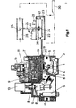
- the gas control device essentially has the structure known from the company publication D3H-29 HONEYWELL "compact valves V4600 / V8600", an embodiment known from DE-PS 26 46 31o being used as the servo pressure regulator.
- the closing body 1 of the main gas valve is spring-loaded in the closing direction by a closing spring 2 and is lifted off the seat by a diaphragm drive when the force exerted on the diaphragm 4 by the control pressure in the chamber 3 exerts the force exerted by the outlet pressure in the outlet 5 on the opposite side of the diaphragm 4 Force plus the force of spring 2 exceeds.
- the drive chamber 3 receives its control pressure via a channel 6 and a solenoid 7 with closing body 8 from the output chamber 9 of a servo pressure regulator 10. This is controlled by a temperature sensor 11, as described in detail in DE-PS 26 46 310. If the outlet pressure in the outlet 5 decreases, the pressure in the chamber 9 and thus also the drive chamber 3 increases, as a result of which the membrane 4 moves the closing body 1 against the force of the spring 2 in the opening direction and thus the gas flow from the inlet 12 to the outlet 5 enlarged.
- the ignition safety device shown in the left part of the drawing with the on button 13, the solenoid insert 14, the safety valve 15 and the pilot burner valve 16 is known from DE-OS 26 05 128 and is of no importance in connection with the present invention.
- the inlet pressure is fed to the pressure regulator 10 via the channel 17 and a throttle point 18, so that the same control pressure builds up behind the throttle point 18 in the space 19 as in the chamber 9.
- the chambers 9 and 19 are above the on-off valve 8 which is open in the operating state shown in connection.
- a second diaphragm drive 21 is connected to the chamber 19 via a line 20 and can optionally be structurally combined with the gas control device. Below its membrane 22, the same servo control pressure prevails in the chamber 23 as in the "r '* drive chamber 3 of the membrane drive for the main gas valve 1.
- the drive rod 24 of an air quantity actuator is present on the membrane 22, which in the exemplary embodiment shown is provided by a throttle valve 25 in the air supply channel 26 is shown.
- a spring 27 abuts a collar 28 of the drive rod on the one hand and is fastened to the drive housing 21 on the other side. Their force counteracts the force exerted by the pressure in the chamber 23.
- the tension of the spring 27 can thus be set the characteristic of the air damper actuator 21. In this way, a desired gas / air ratio can be specified.
- the gas passes and from the air duct 26 the Ver Combustion air to the burner 30.4
- the arrangement is such that, with an increasing amount of gas at the outlet 5 of the gas control device, the amount of air let through by the throttle valve 25 through the air duct 26 to the burner 30 also increases.
- the solenoid valve 7,8 switches over and thus blocks the connection between the chambers 9 and 19, so that the connection of the diaphragm drive 21 to the chamber 19 is advantageous insofar as its separation from the chamber 9 at Closing the valve 8, the closing time of the main valve 1 is not delayed by the additional volume of the drive chamber 23. The latter is rather separated from the volume of the chamber 3, so that the pressure therein can be quickly reduced via the channel 6, the valve 8 and the channel 81 to the outlet side and the main gas valve 1 closes.
- this type of connection of the diaphragm actuator 21 has the advantage that when the main gas valve 1 is closed, the throttle valve 25 goes into its fully open position.
- the drive chamber 23 is now namely supplied via the channel 17 and the throttle point 18 and the channel 20 to the full input pressure without the pressure regulator 10 blowing off part of the same towards the outlet.
- a snap switch 82 is also actuated by the drive rod 24, the contact of which is connected in series with the excitation winding of the solenoid valve 7. As soon as the air flap 25 is closed, this contact interrupts the power supply to the excitation winding of the solenoid valve 7. The position of the throttle valve 25 is thus checked before the burner is started.
- the gas control device can only be started via the solenoid valve 17 when the throttle valve is fully open and the switch 82 is thus closed.
- the switch 82 is actuated via a switching lever 84 which bears against a collar 83 of the drive rod 24. If necessary, further diaphragm drives can be connected to the chamber 19 or the channel 20, for example for closing the chimney when the burner is switched off.
- the second exemplary embodiment corresponding to FIGS. 2 and 3 also uses a servo pressure regulator as described in DE-PS 26 46 310 and DE-OS 29 03 201.
- a servo pressure regulator as described in DE-PS 26 46 310 and DE-OS 29 03 201.
- other servo pressure regulators can also be used.
- the gas control valve has the same structure as in FIG. 1.
- FIG. 2 shows the gas valve including the servo pressure regulator and the air control valve with an upstream fan
- FIG. 3 shows a gas-fired heating boiler as a consumer, for example for a central heating system.
- the drive chamber 31 of a second servo pressure-controlled air control valve 32 is connected here via a line 20 to the chamber 19 of the servo pressure regulator.
- the closing body 33 is supported by the membrane 35 via a pin 34 and is biased in the closing direction by a spring 36.
- the inlet 37 of the air control valve is connected to a compressed air generator in the form of a fan 38, while the sensor 40 of a flow switch 41 is arranged in the outlet 30. Its normally open contact, which is closed by the air flow, lies in the excitation circuit of the closing solenoid valve 4.
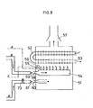
- Fig. 3 shows as a consumer a heat exchanger 52 surrounded by a closed housing 51, the heated one Water passes through outlet 53 to one or more radiators.
- a main burner 54 heats the heat exchanger 52, a pilot burner 55 being connected to the pilot burner connection 65 of the gas control device and a thermocouple 56 monitoring the pilot flame to the magnet insert 14 of the ignition safety device.
- the combustion gases leave the housing 51 through an exhaust 57.
- the inlet 58 of the main burner 54 is opposed by an injector nozzle 59, via which gas flows into the main burner from the outlet 5 of the gas control valve. Due to the jet effect of the nozzle 59, the gas flow simultaneously draws in primary air, which is fed to the main burner 54 as combustion air.
- the housing 51 has an inlet 60 for secondary air, which is opposed by a further injector nozzle 61. It is fed with compressed air by the air control valve 32 and, due to its jet effect, also draws in additional combustion air and presses it into the interior of the housing 51, where it is available to the main burner 54 in order to achieve the most complete possible combustion. Otherwise the housing 51 is closed.
- the arrangement is such that as the amount of gas at the outlet 5 of the gas control device increases, the amount of compressed air let through by the air control valve 32 also increases, and because of the jet effect of the two nozzles 59 and 61, as much primary and secondary air is fed to the main burner 54 as to one complete and optimal combustion of the amount of gas supplied is required.
- the amount of gas let through from the gas control valve to the nozzle 59 is regulated with the aid of the servo pressure regulator 10 as a function of the temperature monitored with the aid of the temperature sensor 11.
- the solenoid valve 7, 8 switches over and thus blocks the connection between the chambers 9 and 19, so it turns out that the connection of the air control valve 32 to the chamber 19 is advantageous in that, by separating it from the chamber 9 when Closing the valve 8, the closing time of the main valve is not delayed by the additional volume of the drive chamber 31. The latter is rather separated from the volume of the chamber 3, so that the pressure therein can be quickly reduced via the channel 6, the valve 8 and the channel 26 to the outlet side and the main gas valve 1 closes.
- the inlet opening 60 is significantly smaller than the secondary air slots of conventional boilers, because the main part of the secondary air is sucked in by the jet effect of the air nozzle 61. If this jet effect ceases to exist, only an insignificant amount of air flows through the inlet 60.
- a modified embodiment is shown in broken lines in FIG. 2, in which the air control valve 32 is omitted and instead a pneumatic-electrical converter 42 is connected to the control air line 20. It is fed, for example, with alternating mains voltage and supplies at its output a direct current for the drive motor 43 of the blower 38 that is proportional to the pneumatic input signal in terms of its current intensity.
- the blower speed and thus the speed of the blower 38 also increase Air volume to, which results in a synchronous gas and air volume control.
- the conversion of the pneumatic input signal of the converter 42 into a signal controlling the motor speed can be carried out in a known manner with the aid of a phase control or a pulse length control.
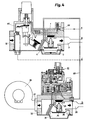
- FIG. 4 Another embodiment of the invention results if the boiler 51 according to FIG. 3 is connected to the control device according to FIG. 4.
- the servo pressure controller 10 does not act on the gas control device 67, but rather on the air control valve 72. The amount of gas is thus tracked to the amount of air supplied. It applies to both embodiments according to FIGS. 2 and 4 that a possible leak in line 20 results in the gas valve and the air valve being closed, so that the arrangement is intrinsically safe in this respect.
- the embodiment according to FIG. 4 also has the advantage that the servo pressure regulator does not work with gas but with air and consequently no gas can escape in the event of any leaks. This makes it possible to manufacture the servo pressure regulator from less demanding materials, for example from plastic. The same applies to the air control valve in both cases.
- Another advantage of the arrangement according to FIG. 4 is that the flow switch 40, 41 can be dispensed with. In this embodiment, the gas valve 67 can only open when the fan 38 is in operation and thus an air flow is present.
- An adjustable throttle 73 which is arranged between the air control valve 32 or 72 on the one hand and the further injector nozzle 61 on the other hand, enables the setting of a desired gas / air ratio and thus an air excess sufficient for good combustion.
- the compressed air source 38 only has to deliver a relatively small amount of air.
- the fan 38 would have to convey about 10m 3 of air.
- the blower 38 itself only has to deliver about 0.5 m 3 . It is also advantageous that fluctuations in the supply pressure are not only corrected for the gas supply, but this also applies equally to the air supply.
Landscapes
- Engineering & Computer Science (AREA)
- Chemical & Material Sciences (AREA)
- Combustion & Propulsion (AREA)
- Mechanical Engineering (AREA)
- General Engineering & Computer Science (AREA)
- Regulation And Control Of Combustion (AREA)
Applications Claiming Priority (4)
| Application Number | Priority Date | Filing Date | Title |
|---|---|---|---|
| DE3010737 | 1980-03-20 | ||
| DE3010737A DE3010737A1 (de) | 1980-03-20 | 1980-03-20 | Gasregelgeraet fuer brenner |
| DE19803044678 DE3044678A1 (de) | 1980-11-27 | 1980-11-27 | Regeleinrichtung fuer brenner |
| DE3044678 | 1980-11-27 |
Publications (2)
| Publication Number | Publication Date |
|---|---|
| EP0036613A1 true EP0036613A1 (fr) | 1981-09-30 |
| EP0036613B1 EP0036613B1 (fr) | 1984-06-06 |
Family
ID=25784424
Family Applications (1)
| Application Number | Title | Priority Date | Filing Date |
|---|---|---|---|
| EP81101973A Expired EP0036613B1 (fr) | 1980-03-20 | 1981-03-17 | Dispositif de régulation pour un échauffeur à eau ou air à combustion gazeuse pouvant être commandé par un capteur de température |
Country Status (3)
| Country | Link |
|---|---|
| EP (1) | EP0036613B1 (fr) |
| DE (1) | DE3163945D1 (fr) |
| DK (1) | DK148726C (fr) |
Cited By (4)
| Publication number | Priority date | Publication date | Assignee | Title |
|---|---|---|---|---|
| EP0062855A1 (fr) * | 1981-04-13 | 1982-10-20 | Honeywell B.V. | Dispositif de régulation pour un dispositif de chauffage à gaz pour eau ou air |
| EP0062854A1 (fr) * | 1981-04-13 | 1982-10-20 | Honeywell B.V. | Dispositif de chauffage à gaz pour eau ou air |
| EP0062856A1 (fr) * | 1981-04-13 | 1982-10-20 | Honeywell B.V. | Dispositif de régulation pour une chaudière à gaz d'une installation de chauffage à eau chaude |
| EP0697563A1 (fr) * | 1994-08-17 | 1996-02-21 | INTEGRA S.r.l. | Assemblage de soupape pour chaudière à gaz |
Families Citing this family (1)
| Publication number | Priority date | Publication date | Assignee | Title |
|---|---|---|---|---|
| WO2022183429A1 (fr) * | 2021-03-04 | 2022-09-09 | Pittway Sarl | Appareil de type brûleur à gaz partiellement prémélangé |
Citations (5)
| Publication number | Priority date | Publication date | Assignee | Title |
|---|---|---|---|---|
| US2193240A (en) * | 1937-10-25 | 1940-03-12 | Cutler Hammer Inc | Method of and apparatus for controlling mixing of combustible gases |
| FR1118768A (fr) * | 1953-12-01 | 1956-06-11 | Combustion Eng | Perfectionnements apportés aux dispositifs de contrôle et de réglage de l'alimentation des foyers de chaudières en charbon pulvérisé et en air comburant |
| DE1031924B (de) * | 1953-10-30 | 1958-06-12 | Georg Hegwein | Sicherheitsvorrichtung fuer Gasfeuerungsanlagen |
| FR1430281A (fr) * | 1965-01-19 | 1966-03-04 | Cem Comp Electro Mec | Perfectionnements aux dispositifs de commande et de sécurité pour installations de brûleurs à gaz |
| NL7811831A (nl) * | 1978-12-04 | 1980-06-06 | Itho B V | Regelinrichting voor een brander. |
-
1981
- 1981-03-17 DE DE8181101973T patent/DE3163945D1/de not_active Expired
- 1981-03-17 EP EP81101973A patent/EP0036613B1/fr not_active Expired
- 1981-03-19 DK DK124681A patent/DK148726C/da not_active IP Right Cessation
Patent Citations (5)
| Publication number | Priority date | Publication date | Assignee | Title |
|---|---|---|---|---|
| US2193240A (en) * | 1937-10-25 | 1940-03-12 | Cutler Hammer Inc | Method of and apparatus for controlling mixing of combustible gases |
| DE1031924B (de) * | 1953-10-30 | 1958-06-12 | Georg Hegwein | Sicherheitsvorrichtung fuer Gasfeuerungsanlagen |
| FR1118768A (fr) * | 1953-12-01 | 1956-06-11 | Combustion Eng | Perfectionnements apportés aux dispositifs de contrôle et de réglage de l'alimentation des foyers de chaudières en charbon pulvérisé et en air comburant |
| FR1430281A (fr) * | 1965-01-19 | 1966-03-04 | Cem Comp Electro Mec | Perfectionnements aux dispositifs de commande et de sécurité pour installations de brûleurs à gaz |
| NL7811831A (nl) * | 1978-12-04 | 1980-06-06 | Itho B V | Regelinrichting voor een brander. |
Cited By (4)
| Publication number | Priority date | Publication date | Assignee | Title |
|---|---|---|---|---|
| EP0062855A1 (fr) * | 1981-04-13 | 1982-10-20 | Honeywell B.V. | Dispositif de régulation pour un dispositif de chauffage à gaz pour eau ou air |
| EP0062854A1 (fr) * | 1981-04-13 | 1982-10-20 | Honeywell B.V. | Dispositif de chauffage à gaz pour eau ou air |
| EP0062856A1 (fr) * | 1981-04-13 | 1982-10-20 | Honeywell B.V. | Dispositif de régulation pour une chaudière à gaz d'une installation de chauffage à eau chaude |
| EP0697563A1 (fr) * | 1994-08-17 | 1996-02-21 | INTEGRA S.r.l. | Assemblage de soupape pour chaudière à gaz |
Also Published As
| Publication number | Publication date |
|---|---|
| DK148726C (da) | 1986-09-22 |
| EP0036613B1 (fr) | 1984-06-06 |
| DE3163945D1 (en) | 1984-07-12 |
| DK148726B (da) | 1985-09-09 |
| DK124681A (da) | 1981-09-21 |
Similar Documents
| Publication | Publication Date | Title |
|---|---|---|
| EP0644377B1 (fr) | Dispositif de commande pour brûleur à gaz | |
| DE3026190A1 (de) | Heizeinrichtung | |
| DE3010014C2 (de) | Vorrichtung zur Einstellung des Verbrennungsluftstromes bei Brenngasverbrauchern | |
| EP0275439B1 (fr) | Dispositif de régulation de puissance de générateurs de chaleur à carburant | |
| EP0957314B1 (fr) | Dispositif de commande pour des brûleurs à gaz | |
| EP0062854B1 (fr) | Dispositif de chauffage à gaz pour eau ou air | |
| EP0062855B1 (fr) | Dispositif de régulation pour un dispositif de chauffage à gaz pour eau ou air | |
| DE2942648A1 (de) | Verbrennungssteuerungseinrichtung fuer einen brenner mit spruehduese | |
| DE3911268A1 (de) | Regeleinrichtung fuer gasbrenner | |
| EP0505714A2 (fr) | Dispositif de commande pour un brûleur de gaz avec un ventilateur pour l'alimentation d'air de combustion | |
| EP0036613A1 (fr) | Dispositif de régulation pour un échauffeur à eau ou air à combustion gazeuse pouvant être commandé par un capteur de température | |
| EP0567060A1 (fr) | Procédé pour commander un brûleur à gaz avec un ventilateur | |
| EP1063481B1 (fr) | Chauffe-eau instantanée à gaz | |
| DE19501749C2 (de) | Verfahren und Vorrichtung zum Steuern eines Gas-Gebläsebrenners | |
| EP0062856B1 (fr) | Dispositif de régulation pour une chaudière à gaz d'une installation de chauffage à eau chaude | |
| EP0103303A2 (fr) | Source de chaleur chauffée au combustible | |
| DE3044678A1 (de) | Regeleinrichtung fuer brenner | |
| EP0866270B1 (fr) | Appareil de chauffage à gaz, notamment un chauffe-eau | |
| AT397851B (de) | Heizgerät | |
| EP0036610B1 (fr) | Procédé de fonctionnement d'une source de chaleur chauffée par combustible | |
| EP0108349A2 (fr) | Source de chaleur chauffée au gaz | |
| DE3333606A1 (de) | Brennstoffbeheizte waermequelle | |
| DE29808799U1 (de) | Regeleinrichtung für Gasbrenner | |
| AT401570B (de) | Verfahren zur steuerung eines gas-gebläsebrenners | |
| DE3147857A1 (de) | Regeleinrichtung |
Legal Events
| Date | Code | Title | Description |
|---|---|---|---|
| PUAI | Public reference made under article 153(3) epc to a published international application that has entered the european phase |
Free format text: ORIGINAL CODE: 0009012 |
|
| AK | Designated contracting states |
Designated state(s): BE DE FR GB IT NL |
|
| 17P | Request for examination filed |
Effective date: 19811028 |
|
| ITF | It: translation for a ep patent filed | ||
| GRAA | (expected) grant |
Free format text: ORIGINAL CODE: 0009210 |
|
| AK | Designated contracting states |
Designated state(s): BE DE FR GB IT NL |
|
| REF | Corresponds to: |
Ref document number: 3163945 Country of ref document: DE Date of ref document: 19840712 |
|
| ET | Fr: translation filed | ||
| PGFP | Annual fee paid to national office [announced via postgrant information from national office to epo] |
Ref country code: NL Payment date: 19850331 Year of fee payment: 5 |
|
| PLBE | No opposition filed within time limit |
Free format text: ORIGINAL CODE: 0009261 |
|
| STAA | Information on the status of an ep patent application or granted ep patent |
Free format text: STATUS: NO OPPOSITION FILED WITHIN TIME LIMIT |
|
| 26N | No opposition filed | ||
| GBPC | Gb: european patent ceased through non-payment of renewal fee | ||
| PG25 | Lapsed in a contracting state [announced via postgrant information from national office to epo] |
Ref country code: BE Effective date: 19860331 |
|
| BERE | Be: lapsed |
Owner name: HONEYWELL B.V. Effective date: 19860331 |
|
| PG25 | Lapsed in a contracting state [announced via postgrant information from national office to epo] |
Ref country code: NL Effective date: 19861001 |
|
| PG25 | Lapsed in a contracting state [announced via postgrant information from national office to epo] |
Ref country code: FR Free format text: LAPSE BECAUSE OF NON-PAYMENT OF DUE FEES Effective date: 19861128 |
|
| NLV4 | Nl: lapsed or anulled due to non-payment of the annual fee | ||
| REG | Reference to a national code |
Ref country code: FR Ref legal event code: ST |
|
| PG25 | Lapsed in a contracting state [announced via postgrant information from national office to epo] |
Ref country code: GB Effective date: 19881118 |
|
| ITTA | It: last paid annual fee | ||
| PGFP | Annual fee paid to national office [announced via postgrant information from national office to epo] |
Ref country code: DE Payment date: 19901221 Year of fee payment: 11 |
|
| PG25 | Lapsed in a contracting state [announced via postgrant information from national office to epo] |
Ref country code: DE Effective date: 19920226 |