EP0866270B1 - Appareil de chauffage à gaz, notamment un chauffe-eau - Google Patents
Appareil de chauffage à gaz, notamment un chauffe-eau Download PDFInfo
- Publication number
- EP0866270B1 EP0866270B1 EP97121200A EP97121200A EP0866270B1 EP 0866270 B1 EP0866270 B1 EP 0866270B1 EP 97121200 A EP97121200 A EP 97121200A EP 97121200 A EP97121200 A EP 97121200A EP 0866270 B1 EP0866270 B1 EP 0866270B1
- Authority
- EP
- European Patent Office
- Prior art keywords
- gas
- air
- individual
- combustion
- fuel
- Prior art date
- Legal status (The legal status is an assumption and is not a legal conclusion. Google has not performed a legal analysis and makes no representation as to the accuracy of the status listed.)
- Expired - Lifetime
Links
Images
Classifications
-
- F—MECHANICAL ENGINEERING; LIGHTING; HEATING; WEAPONS; BLASTING
- F23—COMBUSTION APPARATUS; COMBUSTION PROCESSES
- F23D—BURNERS
- F23D14/00—Burners for combustion of a gas, e.g. of a gas stored under pressure as a liquid
- F23D14/02—Premix gas burners, i.e. in which gaseous fuel is mixed with combustion air upstream of the combustion zone
- F23D14/04—Premix gas burners, i.e. in which gaseous fuel is mixed with combustion air upstream of the combustion zone induction type, e.g. Bunsen burner
- F23D14/045—Premix gas burners, i.e. in which gaseous fuel is mixed with combustion air upstream of the combustion zone induction type, e.g. Bunsen burner with a plurality of burner bars assembled together, e.g. in a grid-like arrangement
-
- F—MECHANICAL ENGINEERING; LIGHTING; HEATING; WEAPONS; BLASTING
- F23—COMBUSTION APPARATUS; COMBUSTION PROCESSES
- F23D—BURNERS
- F23D14/00—Burners for combustion of a gas, e.g. of a gas stored under pressure as a liquid
- F23D14/46—Details, e.g. noise reduction means
- F23D14/60—Devices for simultaneous control of gas and combustion air
-
- F—MECHANICAL ENGINEERING; LIGHTING; HEATING; WEAPONS; BLASTING
- F23—COMBUSTION APPARATUS; COMBUSTION PROCESSES
- F23N—REGULATING OR CONTROLLING COMBUSTION
- F23N1/00—Regulating fuel supply
- F23N1/02—Regulating fuel supply conjointly with air supply
-
- F—MECHANICAL ENGINEERING; LIGHTING; HEATING; WEAPONS; BLASTING
- F23—COMBUSTION APPARATUS; COMBUSTION PROCESSES
- F23N—REGULATING OR CONTROLLING COMBUSTION
- F23N1/00—Regulating fuel supply
- F23N1/02—Regulating fuel supply conjointly with air supply
- F23N1/027—Regulating fuel supply conjointly with air supply using mechanical means
-
- F—MECHANICAL ENGINEERING; LIGHTING; HEATING; WEAPONS; BLASTING
- F23—COMBUSTION APPARATUS; COMBUSTION PROCESSES
- F23N—REGULATING OR CONTROLLING COMBUSTION
- F23N5/00—Systems for controlling combustion
- F23N5/18—Systems for controlling combustion using detectors sensitive to rate of flow of air or fuel
- F23N2005/181—Systems for controlling combustion using detectors sensitive to rate of flow of air or fuel using detectors sensitive to rate of flow of air
-
- F—MECHANICAL ENGINEERING; LIGHTING; HEATING; WEAPONS; BLASTING
- F23—COMBUSTION APPARATUS; COMBUSTION PROCESSES
- F23N—REGULATING OR CONTROLLING COMBUSTION
- F23N2225/00—Measuring
- F23N2225/04—Measuring pressure
- F23N2225/06—Measuring pressure for determining flow
-
- F—MECHANICAL ENGINEERING; LIGHTING; HEATING; WEAPONS; BLASTING
- F23—COMBUSTION APPARATUS; COMBUSTION PROCESSES
- F23N—REGULATING OR CONTROLLING COMBUSTION
- F23N2233/00—Ventilators
- F23N2233/06—Ventilators at the air intake
-
- F—MECHANICAL ENGINEERING; LIGHTING; HEATING; WEAPONS; BLASTING
- F23—COMBUSTION APPARATUS; COMBUSTION PROCESSES
- F23N—REGULATING OR CONTROLLING COMBUSTION
- F23N2235/00—Valves, nozzles or pumps
- F23N2235/12—Fuel valves
- F23N2235/18—Groups of two or more valves
-
- F—MECHANICAL ENGINEERING; LIGHTING; HEATING; WEAPONS; BLASTING
- F23—COMBUSTION APPARATUS; COMBUSTION PROCESSES
- F23N—REGULATING OR CONTROLLING COMBUSTION
- F23N2235/00—Valves, nozzles or pumps
- F23N2235/12—Fuel valves
- F23N2235/20—Membrane valves
-
- F—MECHANICAL ENGINEERING; LIGHTING; HEATING; WEAPONS; BLASTING
- F23—COMBUSTION APPARATUS; COMBUSTION PROCESSES
- F23N—REGULATING OR CONTROLLING COMBUSTION
- F23N2237/00—Controlling
- F23N2237/02—Controlling two or more burners
-
- F—MECHANICAL ENGINEERING; LIGHTING; HEATING; WEAPONS; BLASTING
- F23—COMBUSTION APPARATUS; COMBUSTION PROCESSES
- F23N—REGULATING OR CONTROLLING COMBUSTION
- F23N2237/00—Controlling
- F23N2237/20—Controlling one or more bypass conduits
Definitions
- the invention is based on a gas heater, in particular for water heaters, according to the genus of the main claim.
- a gas heater in particular for water heaters, according to the genus of the main claim.
- known heaters with such a trained Premix burner (DE-A-44 46 945 and Patent Abstracts of Japan, vol. 008, ho. 022 (M-272), January 31 1984 the air becomes the burning zone via a common channel and the gas via one each Single line supplied, the metering of the gas to each firing zone over one in each Single line arranged control valve takes place.
- This Arrangement is relatively complex and not because of inevitable allocation of air to the individual Firing zones also prone to condensation in one Heat exchanger and in the exhaust gas path.
- features of the main claim have the advantage that separate control valves in the gas individual lines omitted and due to the controlled supply of air to the individual burning zones the tendency to form condensate in the Heat exchanger and in the exhaust gas path is reduced.
- the Air supply to the non-activated burning zones remains fully maintained, creating the dew point of the exhaust gases increased and the risk of condensation largely is avoided.
- the air volume flow conveyed derived control pressure for the gas / air compound controller and thus its flawless function remain in the Partial load range of the premix burner fully preserved.
- the dependence of the gas control pressure on the gas volume flow to minimize or to switch off will continue proposed that the gas individual lines in one with the Output of the gas / air compound regulator connected pressure chamber begin and the output pressure to a control element of the Controller leading reference line from one leads flow-free area of the pressure chamber. This ensures that only changes to the static Pressure conditions on the outlet side of the gas / air compound controller be recorded and corrected.
- the pressure chamber can in the Integrated controller or as an independent component be trained.
- a throttle device is provided in the individual gas lines Adjustment of the slope of the gas / air characteristic curve arranged.
- the gas / air composite controller can be advantageous Be adapted to the corresponding system.
- the gas heater can be used with different Gas types are operated.
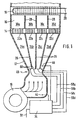
- the heater has a blower 10, the combustion air over feeds an air shaft 12 to a premix burner 14. about this is arranged a combustion chamber 16 through the top a heat exchanger 18 for in a line network 20 running water is complete.
- the premix burner 14 is divided into four burning zones 22, which the air over Individual channels 24a, b, c, d is supplied.
- the individual channels 24 are separated by partition walls 26 in the air shaft 12 separated.
- partition walls 28 Formation of chamber areas 30a, b, c, d provided with the individual channels 24 and the firing zones 22 correspond and are based on the height of the burnout path.
- the fuel gas is the heater via a main line 32 and a device 34 shown in more detail in Figure 2 for Controlling and regulating the performance of the premix burner 14 and of the gas / air ratio.
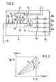
- the device 34 has two safety valves 36, 38 and connected downstream a gas pressure regulator 40 of known type, the control pressure is guided by a pneumatic composite actuator 42. This captures the air volume flow dependent Pressure difference between measuring points 44, 46, of which the one, 44, in the air shaft 12 in front of a constriction 48 and the other, 46, downstream of the constriction in the single channel 24d is arranged.
- the compound actuator 42 acts as known on a servo control valve 50 of the gas pressure regulator 40 and is with this and with the two safety valves 36, 38, as indicated in the drawing, to a gas-air composite fitting 52 structurally summarized.
- the output of the gas pressure regulator 40 is via a line 54 connected to a pressure chamber 56, from the individual lines 58a, b, c, d to in the individual channels 24 of the air shaft 12 arranged gas nozzles 60 lead.
- a Reference line 62 At one flow-reduced area of the pressure chamber 56 is a Reference line 62 connected, which the static Pressure ratios at the controller outlet in a control chamber of the Servo control valve 50 transmits.
- the individual lines 58 is an electromagnetically operated open / close valve 64 installed and each individual line 58 leads over a adjustable throttle device 66, its function below using the characteristic curve image according to FIG. 3 is explained.
- the difference between the pressures p 1 and p 2 which result as a function of the air flow delivered at the two measuring points 44, 46, is plotted on the abscissa of the characteristic curve image.
- the ordinate plots the difference between the regulated gas pressure p BR and the pressure p 2 at the measuring point 46, that is to say the excess pressure with which the gas reaches the respective individual channel 24 forming the mixing chamber.
- the operating behavior according to line a results when the gas flows unthrottled through the throttle device 66. By narrowing the through opening in the throttle device 66, the dashed lines b, c and d result, the distance e representing the possible range of the ratio setting.
- the pressure chamber 56, the on / off valves 64 and optionally the throttle devices 66 could also be used with the Gas / air composite fitting 52 structurally summarized or in these be integrated.
- the individual combustion zones 22 both the air and the gas are fed separately, whereby a good one in the individual channels 24 of the air shaft 12 Mixing of the two combustion components takes place.
- the individual channels 24 have the function of premixing chambers, the combustion zones 22 of the premix burner 14 individually assigned. While the firing zone 22d is permanently activated, the other firing zones 22a, b, c either individually or in groups via the on / off valves 64 can be switched on. It is also about the individual air channels not pressurized 24 conveyed air mixes with the exhaust gases downstream of the heat exchanger 18 and raises their dew point.
- the partitions 28 in the Combustion chamber 16 prevent mixed areas of air with a gas mixture that has not yet been completely burned.
- the power or Control range of the heater can be expanded because also in lower power range due to the air admixture Tendency to form condensate is largely avoided.
- a Extension of the control range is also facilitated or made possible because the detected between the measuring points 44, 46 Control pressure regardless of the number of activated Firing zones 22, i.e. decisive for all performance levels of the Premix burner 14 is.
- Switching individual on and off Firing zones 22 with unchanged air volume can the Do not change the amount of gas supplied to active combustion zones 22, because in the pressure chamber 56 only changes in the static Pressures are detected and regulated by the gas pressure regulator 40.
- the throttle devices 66 can be used for each one Firing zone 22 fine tunes the gas / air ratio made with changing air delivery of the blower 10 become.
Claims (4)
- Appareil de chauffage au gaz notamment chauffe-eau comportant un brûleur à mélange préalable subdivisé en des zones de combustion commandées séparément pour étager la puissance, ces zones recevant l'air comburant fourni en commun par un ventilateur et le gaz combustible de façon régulée chaque fois par une conduite séparée,
caractérisé par les points suivantsl'alimentation en air des zones de combustion non activées restant maintenue complètement.a) l'air comburant comme le gaz combustible est fourni à chaque zone de combustion (22 a, b, c, d) par un canal séparé (24 a, b, c, d),b) une conduite principale (32) alimentant toutes les conduites individuelles de gaz combustible (58 a, b, c, d) comporte un régulateur composite (52) gaz/air commandé par le débit volume d'air,c) les différentes conduites individuelles de gaz combustible (58 a, b, c,d) comportent des vannes ouvertes/fermées (64) pour brancher ou couper l'alimentation gaz des différentes zones de combustion (22 a, b, c, d), - Appareil de chauffage selon la revendication 1,
caractérisé en ce que
dans la chambre de combustion (16) on a également formé des canaux séparés (30 a, b, c, d) qui correspondent aux canaux séparés (24 a, b, c, d) du collecteur d'air (12) ou avec les zones de combustion (22 a, b, c, d) et dont la hauteur dépend de la longueur de combustion. - Appareil de chauffage selon la revendication lou 2,
caractérisé en ce que
les conduites individuelles de gaz combustible (58 a, b, c, d) commencent dans une chambre de pression (56) reliée à la sortie du régulateur composite gaz/air (52), et une ligne de référence (62) transmettant la pression de sortie à un organe de commande (50) du régulateur sort de la zone de la chambre de pression (56) dans laquelle l'écoulement est calmé. - Appareil de chauffage selon l'une des revendications précédentes,
caractérisé en ce que
dans chaque conduite individuelle de gaz combustible (58 a, b, c, d) il est prévu une installation d'étranglement (66) pour régler la pente de la caractéristique gaz/air.
Applications Claiming Priority (2)
| Application Number | Priority Date | Filing Date | Title |
|---|---|---|---|
| DE19711151A DE19711151A1 (de) | 1997-03-18 | 1997-03-18 | Gasheizgerät, insbesondere für Wassererhitzer |
| DE19711151 | 1997-03-18 |
Publications (3)
| Publication Number | Publication Date |
|---|---|
| EP0866270A2 EP0866270A2 (fr) | 1998-09-23 |
| EP0866270A3 EP0866270A3 (fr) | 1999-08-18 |
| EP0866270B1 true EP0866270B1 (fr) | 2003-05-28 |
Family
ID=7823716
Family Applications (1)
| Application Number | Title | Priority Date | Filing Date |
|---|---|---|---|
| EP97121200A Expired - Lifetime EP0866270B1 (fr) | 1997-03-18 | 1997-12-03 | Appareil de chauffage à gaz, notamment un chauffe-eau |
Country Status (2)
| Country | Link |
|---|---|
| EP (1) | EP0866270B1 (fr) |
| DE (2) | DE19711151A1 (fr) |
Families Citing this family (4)
| Publication number | Priority date | Publication date | Assignee | Title |
|---|---|---|---|---|
| US6312250B1 (en) | 1999-04-19 | 2001-11-06 | North American Manufacturing Company | Premix burner with firing rate control |
| DE69929769T2 (de) * | 1999-09-09 | 2006-11-02 | Scanferla, Giorgio, Bassano del Grappa | Brennerbaueinheit und Brennerkopf zur Gasmischungsverbrennung |
| EP1387985B1 (fr) | 2001-05-18 | 2009-10-07 | Bekaert Combustion Technology Bv | Bruleurs a gaz a premelange sans condensation |
| US7494337B2 (en) * | 2004-04-22 | 2009-02-24 | Thomas & Betts International, Inc. | Apparatus and method for providing multiple stages of fuel |
Family Cites Families (5)
| Publication number | Priority date | Publication date | Assignee | Title |
|---|---|---|---|---|
| DE910585C (de) * | 1951-08-01 | 1954-05-03 | Richard Huelzer | Gasbeheizter Fluessigkeits-Durchlauferhitzer |
| JPS58182031A (ja) * | 1982-04-16 | 1983-10-24 | Matsushita Electric Ind Co Ltd | 燃焼制御装置 |
| JP3060730B2 (ja) * | 1992-06-30 | 2000-07-10 | 株式会社ノーリツ | 燃焼装置 |
| DE4446945B4 (de) | 1994-12-28 | 2005-03-17 | Alstom | Gasbetriebener Vormischbrenner |
| JPH09264526A (ja) * | 1996-03-26 | 1997-10-07 | Tokyo Gas Co Ltd | 交番燃焼システム |
-
1997
- 1997-03-18 DE DE19711151A patent/DE19711151A1/de not_active Withdrawn
- 1997-12-03 DE DE59710173T patent/DE59710173D1/de not_active Expired - Fee Related
- 1997-12-03 EP EP97121200A patent/EP0866270B1/fr not_active Expired - Lifetime
Also Published As
| Publication number | Publication date |
|---|---|
| DE59710173D1 (de) | 2003-07-03 |
| EP0866270A3 (fr) | 1999-08-18 |
| DE19711151A1 (de) | 1998-09-24 |
| EP0866270A2 (fr) | 1998-09-23 |
Similar Documents
| Publication | Publication Date | Title |
|---|---|---|
| EP0644377B1 (fr) | Dispositif de commande pour brûleur à gaz | |
| DE2914681C2 (de) | Steuervorrichtung für einen Brenner | |
| DE2832708C2 (fr) | ||
| EP0356690B1 (fr) | Producteur de chaleur chauffé au carburant | |
| EP0062854B1 (fr) | Dispositif de chauffage à gaz pour eau ou air | |
| EP0907052A2 (fr) | Dispositif de commande de rapport pneumatique | |
| DE19724861C1 (de) | Gasbrenner für einen Heizkessel | |
| EP0505714B1 (fr) | Dispositif de commande pour un brûleur de gaz avec un ventilateur pour l'alimentation d'air de combustion | |
| EP2071156B1 (fr) | Système de distribution de carburant d'une turbine à gaz avec ensemble brûleur à plusieurs étages | |
| EP0866270B1 (fr) | Appareil de chauffage à gaz, notamment un chauffe-eau | |
| DE2906223A1 (de) | Brennstoffsteuerung fuer turbinen-nachbrenner | |
| DE19822336C2 (de) | Vorrichtung zum Betreiben eines atmosphärischen, insbesondere vollvormischenden Gasbrenners | |
| DE3927416C2 (de) | Gaszentralheizungsbrenner | |
| DE2752663A1 (de) | Gasheizgeraet | |
| EP1028287A1 (fr) | Brûleur atmosphérique à gaz et distributeur de gaz pour un brûleur à gaz | |
| DE102011002324A1 (de) | Regeleinrichtung für einen Brenner und Verfahren zum Betrieb eines Brenners | |
| DE3826279C2 (de) | Gasbrenner mit einer Brennerkammer | |
| DE19810750A1 (de) | Verfahren und Vorrichtung zum Betreiben eines atmosphärischen Gasbrenners | |
| AT395764B (de) | Vormischgasbrenner | |
| EP0916895B1 (fr) | Procédé pour commander un brûleur atmosphérique à gaz pour un appareil de chauffage, notamment un chauffe-eau | |
| EP0908670B1 (fr) | Dispositif pour actionner un brûleur atmosphérique à gaz | |
| DE19503781A1 (de) | Öl- oder Gasgebläsebrenner | |
| EP0036613A1 (fr) | Dispositif de régulation pour un échauffeur à eau ou air à combustion gazeuse pouvant être commandé par un capteur de température | |
| EP0108349A2 (fr) | Source de chaleur chauffée au gaz | |
| EP0733857B1 (fr) | Dispositif de commande d'un brûleur avec une chambre pour l'air de combustion |
Legal Events
| Date | Code | Title | Description |
|---|---|---|---|
| PUAI | Public reference made under article 153(3) epc to a published international application that has entered the european phase |
Free format text: ORIGINAL CODE: 0009012 |
|
| AK | Designated contracting states |
Kind code of ref document: A2 Designated state(s): DE FR GB IT NL |
|
| AX | Request for extension of the european patent |
Free format text: AL;LT;LV;MK;RO;SI |
|
| PUAL | Search report despatched |
Free format text: ORIGINAL CODE: 0009013 |
|
| AK | Designated contracting states |
Kind code of ref document: A3 Designated state(s): AT BE CH DE DK ES FI FR GB GR IE IT LI LU MC NL PT SE |
|
| AX | Request for extension of the european patent |
Free format text: AL;LT;LV;MK;RO;SI |
|
| 17P | Request for examination filed |
Effective date: 20000218 |
|
| AKX | Designation fees paid |
Free format text: DE FR GB IT NL |
|
| GRAH | Despatch of communication of intention to grant a patent |
Free format text: ORIGINAL CODE: EPIDOS IGRA |
|
| GRAH | Despatch of communication of intention to grant a patent |
Free format text: ORIGINAL CODE: EPIDOS IGRA |
|
| GRAA | (expected) grant |
Free format text: ORIGINAL CODE: 0009210 |
|
| AK | Designated contracting states |
Designated state(s): DE FR GB IT NL |
|
| PG25 | Lapsed in a contracting state [announced via postgrant information from national office to epo] |
Ref country code: NL Free format text: LAPSE BECAUSE OF FAILURE TO SUBMIT A TRANSLATION OF THE DESCRIPTION OR TO PAY THE FEE WITHIN THE PRESCRIBED TIME-LIMIT Effective date: 20030528 Ref country code: IT Free format text: LAPSE BECAUSE OF FAILURE TO SUBMIT A TRANSLATION OF THE DESCRIPTION OR TO PAY THE FEE WITHIN THE PRE;WARNING: LAPSES OF ITALIAN PATENTS WITH EFFECTIVE DATE BEFORE 2007 MAY HAVE OCCURRED AT ANY TIME BEFORE 2007. THE CORRECT EFFECTIVE DATE MAY BE DIFFERENT FROM THE ONE RECORDED.SCRIBED TIME-LIMIT Effective date: 20030528 Ref country code: GB Free format text: LAPSE BECAUSE OF FAILURE TO SUBMIT A TRANSLATION OF THE DESCRIPTION OR TO PAY THE FEE WITHIN THE PRESCRIBED TIME-LIMIT Effective date: 20030528 Ref country code: FR Free format text: LAPSE BECAUSE OF FAILURE TO SUBMIT A TRANSLATION OF THE DESCRIPTION OR TO PAY THE FEE WITHIN THE PRESCRIBED TIME-LIMIT Effective date: 20030528 |
|
| REG | Reference to a national code |
Ref country code: GB Ref legal event code: FG4D Free format text: NOT ENGLISH |
|
| REF | Corresponds to: |
Ref document number: 59710173 Country of ref document: DE Date of ref document: 20030703 Kind code of ref document: P |
|
| NLV1 | Nl: lapsed or annulled due to failure to fulfill the requirements of art. 29p and 29m of the patents act | ||
| GBV | Gb: ep patent (uk) treated as always having been void in accordance with gb section 77(7)/1977 [no translation filed] |
Effective date: 20030528 |
|
| PLBE | No opposition filed within time limit |
Free format text: ORIGINAL CODE: 0009261 |
|
| STAA | Information on the status of an ep patent application or granted ep patent |
Free format text: STATUS: NO OPPOSITION FILED WITHIN TIME LIMIT |
|
| 26N | No opposition filed |
Effective date: 20040302 |
|
| EN | Fr: translation not filed | ||
| PGFP | Annual fee paid to national office [announced via postgrant information from national office to epo] |
Ref country code: DE Payment date: 20050208 Year of fee payment: 8 |
|
| PG25 | Lapsed in a contracting state [announced via postgrant information from national office to epo] |
Ref country code: DE Free format text: LAPSE BECAUSE OF NON-PAYMENT OF DUE FEES Effective date: 20060701 |