EP0907052A2 - Dispositif de commande de rapport pneumatique - Google Patents
Dispositif de commande de rapport pneumatique Download PDFInfo
- Publication number
- EP0907052A2 EP0907052A2 EP98113154A EP98113154A EP0907052A2 EP 0907052 A2 EP0907052 A2 EP 0907052A2 EP 98113154 A EP98113154 A EP 98113154A EP 98113154 A EP98113154 A EP 98113154A EP 0907052 A2 EP0907052 A2 EP 0907052A2
- Authority
- EP
- European Patent Office
- Prior art keywords
- pressure
- pressure regulator
- control device
- fluid
- ratio
- Prior art date
- Legal status (The legal status is an assumption and is not a legal conclusion. Google has not performed a legal analysis and makes no representation as to the accuracy of the status listed.)
- Withdrawn
Links
Images

Classifications
-
- G—PHYSICS
- G05—CONTROLLING; REGULATING
- G05D—SYSTEMS FOR CONTROLLING OR REGULATING NON-ELECTRIC VARIABLES
- G05D16/00—Control of fluid pressure
- G05D16/14—Control of fluid pressure with auxiliary non-electric power
- G05D16/16—Control of fluid pressure with auxiliary non-electric power derived from the controlled fluid
- G05D16/163—Control of fluid pressure with auxiliary non-electric power derived from the controlled fluid using membranes within the main valve
-
- F—MECHANICAL ENGINEERING; LIGHTING; HEATING; WEAPONS; BLASTING
- F23—COMBUSTION APPARATUS; COMBUSTION PROCESSES
- F23D—BURNERS
- F23D14/00—Burners for combustion of a gas, e.g. of a gas stored under pressure as a liquid
- F23D14/46—Details
- F23D14/60—Devices for simultaneous control of gas and combustion air
-
- F—MECHANICAL ENGINEERING; LIGHTING; HEATING; WEAPONS; BLASTING
- F23—COMBUSTION APPARATUS; COMBUSTION PROCESSES
- F23N—REGULATING OR CONTROLLING COMBUSTION
- F23N1/00—Regulating fuel supply
- F23N1/02—Regulating fuel supply conjointly with air supply
- F23N1/027—Regulating fuel supply conjointly with air supply using mechanical means
-
- F—MECHANICAL ENGINEERING; LIGHTING; HEATING; WEAPONS; BLASTING
- F23—COMBUSTION APPARATUS; COMBUSTION PROCESSES
- F23N—REGULATING OR CONTROLLING COMBUSTION
- F23N2225/00—Measuring
- F23N2225/04—Measuring pressure
-
- F—MECHANICAL ENGINEERING; LIGHTING; HEATING; WEAPONS; BLASTING
- F23—COMBUSTION APPARATUS; COMBUSTION PROCESSES
- F23N—REGULATING OR CONTROLLING COMBUSTION
- F23N2235/00—Valves, nozzles or pumps
- F23N2235/12—Fuel valves
- F23N2235/20—Membrane valves
Definitions
- the invention relates to a control device for compliance an at least almost always the same relationship between the pressure of a first, in particular gaseous Fluids, preferably a fuel gas, and the pressure of a second, in particular gaseous fluids, preferably from Air, shortly before it is brought together in a mixing room, preferably in a firebox of a gas burner independently of that in the mixing room opposite the pressures of the two Fluid prevailing negative pressure, with one in the mixing space leading main line for the first fluid and with a Pressure regulator of the one in the main line Inlet pressure of the first fluid depending on the required Pressure ratio.
- a first in particular gaseous Fluids
- a second, in particular gaseous fluids preferably from Air
- Such an adjusting device is e.g. through the DE 25 47 075 C3 has become known.
- Gas firing systems that ensure that the gas / air pressure ratio of one for an optimal combustion desired value in the entire performance range the gas burner system as little as possible deviates.
- the amount of gas / air mixture supplied to the gas firing depends on the currently required Heating output that can fluctuate in large areas.
- the so-called “pneumatic Compound regulator” the pressure of the gas based on the pressure loss changed at a throttle to always do that to achieve the same mixing ratio.
- To build relationships are usually two membranes and a comparative balance lever needed.
- Common to all pneumatic compound controllers also the possibility of considering the Press in the combustion chamber of the gas burner system so that the the mass flow from the burner into the combustion chamber is crucial Pressure difference in the gas mixture composition taken into account can be.
- the present invention has the object based on a control device of the type mentioned to further develop that the desired always the same Pressure ratio between the first fluid (fuel gas) and the second fluid (air) just before the common mixing room (Combustion chamber) as simple as possible and with few components can be adjusted.
- This control device allows inexpensive metering of the fuel gas in almost always the correct ratio to incoming combustion air in gas burners or in general for devices or machines that consist of a certain mixture need a first and a second fluid.
- This control device enables this correct metering in one large operating load range in a non-mechanical manner few components and with a particularly small installation space.
- the regulated pressure of the first fluid flows through the two Throttles (e.g. nozzles) in the mixing room.
- Throttles e.g. nozzles
- the fluid pressure prevailing upstream of the control element reduced in the desired ratio as a control variable the pressure regulator.
- the pressure regulator does not regulate how usual - e.g. to zero pressure, but to a higher one Pressure caused by the ratio of pressure drops to the two throttles is determined.
- the Throttle cross sections is the desired pressure ratio determined both fluids.
- the ratio of the throttle cross sections of the two throttles arranged one behind the other can be changed in order to same control device on another if necessary to be able to adjust the pressure ratio of the two fluids.
- chokes with different cross sections be interchangeable.
- throttle cross section of at least one throttle continuously adjustable to the pressure ratio within to be able to set certain limits as desired.
- continuous acting throttle can e.g. one in the flow cross section screw-in set screw may be provided.
- the throttle cross section of at least one Throttle also by connecting or switching one or more other chokes can be changed.
- the Pressure regulator on a control membrane, one side of which with the reduced pressure of the first fluid and its other side is acted upon by the pressure of the second fluid, so that the control element of the pressure regulator the pressure of the first Fluids corresponding to the pressure difference between the reduced Pressure of the first fluid and the pressure of the second Fluid sets.
- Control element of the pressure regulator that adjusts the inlet pressure are in drive connection with the control diaphragm.
- actuator and control diaphragm rigid with each other be connected.
- the control element of the pressure regulator is preferably opposed gravity and upstream inlet pressure of the first fluid, in particular spring-loaded, so that according to the over the throttle cross sections set pressure ratio a resulting A force acts which controls the first fluid flow Actuator only against e.g. the power of a spring more or less wide opens.
- the pressure regulator is a zero pressure regulator.
- starting point can be a conventional zero pressure regulator, its pressure measuring point not directly at the exit of the first, as usual Fluid is, but the pressure of the first fluid reaches reduced in the desired ratio by the first throttle as a controlled variable to the pressure regulator.
- the zero pressure regulator preferably has a zero pressure adjustment on.
- a spring preload on the pressure regulator can be a performance-related change the mixing ratio can be achieved. It affects prefers the lower power range.
- the pressure regulator can also be designed as a servo pressure regulator be. This can be the upstream of the bypass line prevailing input pressure adjusting actuator of Servo controller over the first fluid according to the difference between the reduced pressure of the first fluid and the Pressure of the second fluid are operated.
- the chokes can, especially with new devices, already in the pressure regulator can be integrated, or in a separate one Throttle part can be provided, which to a conventional Pressure regulator can be connected.
- the invention also relates to a separate throttle part at least two chokes arranged one behind the other for the Control device described above, wherein the throttle part a conventional pressure regulator can be connected.
- the Throttle part becomes the pressure measuring point of the first fluid e.g. not as usual with a conventional zero pressure regulator directly pressurized with the first fluid is reduced in the desired ratio by the first throttle passed to the actuator of the pressure regulator.
- the gas pressure regulator does not regulate to zero pressure, as usual, but to a higher pressure caused by the ratio the pressure loss at the two throttles is determined.
- This Throttle part can the adjustable, described above, have interchangeable or switchable or connectable chokes.
- FIG. 1, 1 denotes a control device according to the invention for automatically setting the correct pressure ratio between a fuel gas (first fluid ) 2 and air (second fluid) 3 , shortly before it is introduced separately into a common combustion chamber (mixing chamber) 4 of a gas burner 5 will.
- the fuel gas 2 supplied via a gas line 6 flows into a main line 8 , from which it exits into the combustion chamber 4 via a gas nozzle 9 .
- a negative pressure (combustion chamber back pressure) p F is generated by means of a fan 10 , so that the fuel gas 2 and atmospheric air 3 are sucked in.
- the power of the gas burner 5 is set by different speeds of the fan motor, ie by a changed vacuum p F.
- the fuel gas pressure p Br prevailing in the main line 8 in front of the gas nozzle 9 can be set via an adjusting element 11 in the main line 8, which is part of a pressure regulator 12 .
- a bypass line 13 branches off from the main line 8 between the control element 11 and the gas nozzle 9 and also leads into the combustion chamber 4.
- two throttles 14 and 15 are arranged one behind the other, between which there is a reduced fuel gas pressure p red .
- This reduced fuel gas pressure p red is fed via a line 16 located between the throttles 14, 15 to the pressure regulator 12 as a controlled variable which, according to the pressure ratio p L / p Br, between the air pressure p L at the gas burner 5 and the reduced fuel gas pressure p red via the control element 11, for example via a gas valve, adjusts the fuel gas pressure p Br in the main line 8.
- control element 11 is in drive connection with a control membrane 17 in the pressure regulator 12, on one side of which the reduced fuel gas pressure p red and on the other side of which the air pressure p L acts.
- a restoring force of the control membrane 17 can be adjusted by changing the pretension of a spring 18 which acts on the control membrane 17 (zero pressure adjustment).
- the pressure regulator 12 is set to approximately zero pressure, so that the actuating element 11 is actuated only pneumatically by the applied pressures, p L and p red . That is, the control element 11 is opened or closed until a pressure difference no longer acts on the control diaphragm 17.
- n indicates the cross-sectional ratio between the first throttle 14 and the second throttle 15.
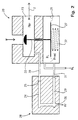
- FIG. 2 shows a conventional zero pressure regulator 20 , the control membrane 21 of which is not, as usual, with the gas pressure p Br prevailing in the main line 23 downstream of the control element 22 , but via the bypass line 24 with the ratio reduced by the two throttles 25 , 26 in the desired ratio Gas pressure p red is applied.
- the air pressure p L acts on the other side of the control membrane 21, and the actuating element 22 is rigidly connected to a membrane plate 27 of the control membrane 21.
- the throttles 25, 26 are provided in a separate throttle part 28 , the bypass line 24 and the line 29 of the throttle part 28 being connected to corresponding external connections 30 , 31 of the zero pressure regulator 20.
- a spring 32 acting on the diaphragm plate 27 serves to compensate for gravity and the upstream gas inlet pressure acting on the actuating element 22.
- this zero pressure regulator 20 does not regulate as usual at zero pressure, but at a higher pressure, which is due to the ratio of pressure drops across the two Chokes 25, 26 is determined.
- the pressure ratio can be variable be by different chokes or an adjustable Choke can be used.
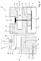
- FIG. 3 shows a servo pressure regulator 40 with a control diaphragm 41 , the lower working chamber 42 of which is not, as usual, with the gas pressure p Br prevailing in the main line 44 downstream of the actuating element 43 , but via the bypass line 45 with that through the two throttles 46 , 47 reduced gas pressure p red is applied in the desired ratio.
- the air pressure p L acts on the other side of the control diaphragm 41.
- a diaphragm plate 48 connected to the control diaphragm 41 controls the outflow of the fuel gas within a servo line 50 opening into the lower working space 42 in accordance with the ratio p red / p L and the prestress by the spring 49 .
- this servo pressure regulator 40 also regulates not to zero pressure as usual, but to a higher one Pressure caused by the ratio of pressure drops to the two throttles 46, 47 is determined.
- Adjusting screw trained second throttle 47 is the throttle cross section continuously adjustable and thus that Pressure ratio adjustable within certain limits.
Landscapes
- Engineering & Computer Science (AREA)
- Chemical & Material Sciences (AREA)
- Combustion & Propulsion (AREA)
- Mechanical Engineering (AREA)
- General Engineering & Computer Science (AREA)
- Physics & Mathematics (AREA)
- Power Engineering (AREA)
- Fluid Mechanics (AREA)
- General Physics & Mathematics (AREA)
- Automation & Control Theory (AREA)
- Control Of Fluid Pressure (AREA)
- Regulation And Control Of Combustion (AREA)
Applications Claiming Priority (2)
| Application Number | Priority Date | Filing Date | Title |
|---|---|---|---|
| DE19740666 | 1997-09-16 | ||
| DE19740666A DE19740666C1 (de) | 1997-09-16 | 1997-09-16 | Regelvorrichtung für das Einhalten eines geforderten Gas-/Luft-Verhältnisses für Gasbrenner |
Publications (1)
| Publication Number | Publication Date |
|---|---|
| EP0907052A2 true EP0907052A2 (fr) | 1999-04-07 |
Family
ID=7842496
Family Applications (1)
| Application Number | Title | Priority Date | Filing Date |
|---|---|---|---|
| EP98113154A Withdrawn EP0907052A2 (fr) | 1997-09-16 | 1998-07-15 | Dispositif de commande de rapport pneumatique |
Country Status (2)
| Country | Link |
|---|---|
| EP (1) | EP0907052A2 (fr) |
| DE (1) | DE19740666C1 (fr) |
Cited By (21)
| Publication number | Priority date | Publication date | Assignee | Title |
|---|---|---|---|---|
| CN100464069C (zh) * | 2007-03-26 | 2009-02-25 | 应城市新世纪摩托车配件有限责任公司 | 带负压传感器的空燃比控制阀 |
| US8839815B2 (en) | 2011-12-15 | 2014-09-23 | Honeywell International Inc. | Gas valve with electronic cycle counter |
| US8899264B2 (en) | 2011-12-15 | 2014-12-02 | Honeywell International Inc. | Gas valve with electronic proof of closure system |
| US8905063B2 (en) | 2011-12-15 | 2014-12-09 | Honeywell International Inc. | Gas valve with fuel rate monitor |
| US8947242B2 (en) | 2011-12-15 | 2015-02-03 | Honeywell International Inc. | Gas valve with valve leakage test |
| US9074770B2 (en) | 2011-12-15 | 2015-07-07 | Honeywell International Inc. | Gas valve with electronic valve proving system |
| US9234661B2 (en) | 2012-09-15 | 2016-01-12 | Honeywell International Inc. | Burner control system |
| US9557059B2 (en) | 2011-12-15 | 2017-01-31 | Honeywell International Inc | Gas valve with communication link |
| US9645584B2 (en) | 2014-09-17 | 2017-05-09 | Honeywell International Inc. | Gas valve with electronic health monitoring |
| US9683674B2 (en) | 2013-10-29 | 2017-06-20 | Honeywell Technologies Sarl | Regulating device |
| US9835265B2 (en) | 2011-12-15 | 2017-12-05 | Honeywell International Inc. | Valve with actuator diagnostics |
| US9841122B2 (en) | 2014-09-09 | 2017-12-12 | Honeywell International Inc. | Gas valve with electronic valve proving system |
| US9846440B2 (en) | 2011-12-15 | 2017-12-19 | Honeywell International Inc. | Valve controller configured to estimate fuel comsumption |
| US9851103B2 (en) | 2011-12-15 | 2017-12-26 | Honeywell International Inc. | Gas valve with overpressure diagnostics |
| US9995486B2 (en) | 2011-12-15 | 2018-06-12 | Honeywell International Inc. | Gas valve with high/low gas pressure detection |
| US10024439B2 (en) | 2013-12-16 | 2018-07-17 | Honeywell International Inc. | Valve over-travel mechanism |
| US10422531B2 (en) | 2012-09-15 | 2019-09-24 | Honeywell International Inc. | System and approach for controlling a combustion chamber |
| US10503181B2 (en) | 2016-01-13 | 2019-12-10 | Honeywell International Inc. | Pressure regulator |
| US10564062B2 (en) | 2016-10-19 | 2020-02-18 | Honeywell International Inc. | Human-machine interface for gas valve |
| US10697815B2 (en) | 2018-06-09 | 2020-06-30 | Honeywell International Inc. | System and methods for mitigating condensation in a sensor module |
| US11073281B2 (en) | 2017-12-29 | 2021-07-27 | Honeywell International Inc. | Closed-loop programming and control of a combustion appliance |
Families Citing this family (4)
| Publication number | Priority date | Publication date | Assignee | Title |
|---|---|---|---|---|
| DE29908550U1 (de) | 1999-05-14 | 1999-08-12 | Honeywell B.V., Amsterdam | Vorrichtung zum Erzeugen eines Gemisches aus Gas und Verbrennungsluft für einen Brenner |
| DE10340045A1 (de) | 2003-08-28 | 2005-03-24 | Karl Dungs Gmbh & Co. Kg | Verhältnisregler mit dynamischer Verhältnisbildung |
| DE102004038673B3 (de) * | 2004-08-09 | 2006-03-30 | Karl Dungs Gmbh & Co. Kg | Servodruckregler |
| DE102021127223A1 (de) | 2021-10-20 | 2023-04-20 | Ebm-Papst Landshut Gmbh | Verfahren zur modellprädiktiven Regelung eines Brennstoff-Luft-Gemisches eines Systems sowie ein zugehöriges System |
Citations (1)
| Publication number | Priority date | Publication date | Assignee | Title |
|---|---|---|---|---|
| DE2547075A1 (de) | 1975-09-19 | 1977-03-31 | Landis & Gyr Ag | Regeleinrichtung fuer das gas/luftverhaeltnis bei der leistungssteuerung von gasgeblaesebrennern |
Family Cites Families (1)
| Publication number | Priority date | Publication date | Assignee | Title |
|---|---|---|---|---|
| DE2708858C2 (de) * | 1977-03-01 | 1986-04-24 | Caloric Gesellschaft für Apparatebau mbH, 8032 Gräfelfing | Regeleinrichtung für einen Brenner für fließfähige Brennstoffe |
-
1997
- 1997-09-16 DE DE19740666A patent/DE19740666C1/de not_active Expired - Fee Related
-
1998
- 1998-07-15 EP EP98113154A patent/EP0907052A2/fr not_active Withdrawn
Patent Citations (1)
| Publication number | Priority date | Publication date | Assignee | Title |
|---|---|---|---|---|
| DE2547075A1 (de) | 1975-09-19 | 1977-03-31 | Landis & Gyr Ag | Regeleinrichtung fuer das gas/luftverhaeltnis bei der leistungssteuerung von gasgeblaesebrennern |
Cited By (27)
| Publication number | Priority date | Publication date | Assignee | Title |
|---|---|---|---|---|
| CN100464069C (zh) * | 2007-03-26 | 2009-02-25 | 应城市新世纪摩托车配件有限责任公司 | 带负压传感器的空燃比控制阀 |
| US10697632B2 (en) | 2011-12-15 | 2020-06-30 | Honeywell International Inc. | Gas valve with communication link |
| US10851993B2 (en) | 2011-12-15 | 2020-12-01 | Honeywell International Inc. | Gas valve with overpressure diagnostics |
| US8905063B2 (en) | 2011-12-15 | 2014-12-09 | Honeywell International Inc. | Gas valve with fuel rate monitor |
| US8947242B2 (en) | 2011-12-15 | 2015-02-03 | Honeywell International Inc. | Gas valve with valve leakage test |
| US9074770B2 (en) | 2011-12-15 | 2015-07-07 | Honeywell International Inc. | Gas valve with electronic valve proving system |
| US9995486B2 (en) | 2011-12-15 | 2018-06-12 | Honeywell International Inc. | Gas valve with high/low gas pressure detection |
| US8899264B2 (en) | 2011-12-15 | 2014-12-02 | Honeywell International Inc. | Gas valve with electronic proof of closure system |
| US9557059B2 (en) | 2011-12-15 | 2017-01-31 | Honeywell International Inc | Gas valve with communication link |
| US9851103B2 (en) | 2011-12-15 | 2017-12-26 | Honeywell International Inc. | Gas valve with overpressure diagnostics |
| US9846440B2 (en) | 2011-12-15 | 2017-12-19 | Honeywell International Inc. | Valve controller configured to estimate fuel comsumption |
| US9835265B2 (en) | 2011-12-15 | 2017-12-05 | Honeywell International Inc. | Valve with actuator diagnostics |
| US8839815B2 (en) | 2011-12-15 | 2014-09-23 | Honeywell International Inc. | Gas valve with electronic cycle counter |
| US11421875B2 (en) | 2012-09-15 | 2022-08-23 | Honeywell International Inc. | Burner control system |
| US9657946B2 (en) | 2012-09-15 | 2017-05-23 | Honeywell International Inc. | Burner control system |
| US9234661B2 (en) | 2012-09-15 | 2016-01-12 | Honeywell International Inc. | Burner control system |
| US10422531B2 (en) | 2012-09-15 | 2019-09-24 | Honeywell International Inc. | System and approach for controlling a combustion chamber |
| US10215291B2 (en) | 2013-10-29 | 2019-02-26 | Honeywell International Inc. | Regulating device |
| US9683674B2 (en) | 2013-10-29 | 2017-06-20 | Honeywell Technologies Sarl | Regulating device |
| US10024439B2 (en) | 2013-12-16 | 2018-07-17 | Honeywell International Inc. | Valve over-travel mechanism |
| US9841122B2 (en) | 2014-09-09 | 2017-12-12 | Honeywell International Inc. | Gas valve with electronic valve proving system |
| US10203049B2 (en) | 2014-09-17 | 2019-02-12 | Honeywell International Inc. | Gas valve with electronic health monitoring |
| US9645584B2 (en) | 2014-09-17 | 2017-05-09 | Honeywell International Inc. | Gas valve with electronic health monitoring |
| US10503181B2 (en) | 2016-01-13 | 2019-12-10 | Honeywell International Inc. | Pressure regulator |
| US10564062B2 (en) | 2016-10-19 | 2020-02-18 | Honeywell International Inc. | Human-machine interface for gas valve |
| US11073281B2 (en) | 2017-12-29 | 2021-07-27 | Honeywell International Inc. | Closed-loop programming and control of a combustion appliance |
| US10697815B2 (en) | 2018-06-09 | 2020-06-30 | Honeywell International Inc. | System and methods for mitigating condensation in a sensor module |
Also Published As
| Publication number | Publication date |
|---|---|
| DE19740666C1 (de) | 1999-01-07 |
Similar Documents
| Publication | Publication Date | Title |
|---|---|---|
| EP0907052A2 (fr) | Dispositif de commande de rapport pneumatique | |
| DE19515286C2 (de) | Druckregler zum Erzeugen eines geregelten Steuerdrucks für ein membrangesteuertes Gasventil | |
| DE3030765C2 (de) | Elektronisch geregeltes Mischventil | |
| DE19722600C2 (de) | Servoregler | |
| EP0652501B1 (fr) | Appareil de positionnement multiple avec régulateur d'entrée | |
| EP1510756A1 (fr) | Régulateur de rapport avec évaluation dynamique du rapport | |
| EP1882882A2 (fr) | Régulateur de débit | |
| EP1626321B1 (fr) | Régulateur de pression et son procédé de controle | |
| EP0957314B1 (fr) | Dispositif de commande pour des brûleurs à gaz | |
| EP0390964B1 (fr) | Dispositif de commande pour brûleur à gaz | |
| EP0450173A1 (fr) | Dispositif de régulation de mélange pour des brûleurs à gaz à mélange | |
| DE2830675C2 (de) | Vorrichtung zur Regelung des Luftkraftstoffgemisches einer Brennkraftmaschine | |
| DE2844350C2 (de) | Brennstoffregelvorrichtung für Gasturbinentriebwerke | |
| EP0707863A1 (fr) | Dispositif de réglage de la proportion de gaz pour appareil d'anesthésie | |
| DE4019757A1 (de) | Membrangesteuerter gasdruckregler | |
| DE2906223A1 (de) | Brennstoffsteuerung fuer turbinen-nachbrenner | |
| EP0041247A2 (fr) | Dispositif asservi pour réglage de débit indépendant de la charge | |
| DE2316952B2 (de) | Brennstoffregelvorrichtung für die einzelnen Brenner einer Nachbrennereinrichtung eines Gasturbinenstrahltriebwerks | |
| EP0044518A1 (fr) | Dispositif de régulation du débit d'une pompe réglable | |
| DE2831053C2 (de) | Brennstoff-Zuführeinrichtung für eine Brennkraftmaschine | |
| DE19906935A1 (de) | Gasbrenner sowie Verfahren zum Betreiben eines Gasbrenners | |
| DE2947216A1 (de) | Vorrichtung zum regeln des durchflusses stroemender medien | |
| EP0103303A2 (fr) | Source de chaleur chauffée au combustible | |
| DE2423543C2 (de) | Brennstoffregeleinrichtung für eine Gasturbinenanlage | |
| DE2834242A1 (de) | Gemisch-regeleinrichtung fuer gasgeblaesebrenner |
Legal Events
| Date | Code | Title | Description |
|---|---|---|---|
| PUAI | Public reference made under article 153(3) epc to a published international application that has entered the european phase |
Free format text: ORIGINAL CODE: 0009012 |
|
| AK | Designated contracting states |
Kind code of ref document: A2 Designated state(s): AT BE CH CY DE DK ES FI FR GB GR IE IT LI LU MC NL PT SE |
|
| AX | Request for extension of the european patent |
Free format text: AL;LT;LV;MK;RO;SI |
|
| STAA | Information on the status of an ep patent application or granted ep patent |
Free format text: STATUS: THE APPLICATION IS DEEMED TO BE WITHDRAWN |
|
| 18D | Application deemed to be withdrawn |
Effective date: 20010201 |