EP0957314B1 - Dispositif de commande pour des brûleurs à gaz - Google Patents
Dispositif de commande pour des brûleurs à gaz Download PDFInfo
- Publication number
- EP0957314B1 EP0957314B1 EP99109002A EP99109002A EP0957314B1 EP 0957314 B1 EP0957314 B1 EP 0957314B1 EP 99109002 A EP99109002 A EP 99109002A EP 99109002 A EP99109002 A EP 99109002A EP 0957314 B1 EP0957314 B1 EP 0957314B1
- Authority
- EP
- European Patent Office
- Prior art keywords
- gas
- pressure
- pressure regulator
- control device
- valve
- Prior art date
- Legal status (The legal status is an assumption and is not a legal conclusion. Google has not performed a legal analysis and makes no representation as to the accuracy of the status listed.)
- Expired - Lifetime
Links
Images


Classifications
-
- F—MECHANICAL ENGINEERING; LIGHTING; HEATING; WEAPONS; BLASTING
- F23—COMBUSTION APPARATUS; COMBUSTION PROCESSES
- F23D—BURNERS
- F23D14/00—Burners for combustion of a gas, e.g. of a gas stored under pressure as a liquid
- F23D14/46—Details, e.g. noise reduction means
- F23D14/60—Devices for simultaneous control of gas and combustion air
-
- F—MECHANICAL ENGINEERING; LIGHTING; HEATING; WEAPONS; BLASTING
- F23—COMBUSTION APPARATUS; COMBUSTION PROCESSES
- F23N—REGULATING OR CONTROLLING COMBUSTION
- F23N1/00—Regulating fuel supply
- F23N1/02—Regulating fuel supply conjointly with air supply
- F23N1/022—Regulating fuel supply conjointly with air supply using electronic means
-
- F—MECHANICAL ENGINEERING; LIGHTING; HEATING; WEAPONS; BLASTING
- F23—COMBUSTION APPARATUS; COMBUSTION PROCESSES
- F23N—REGULATING OR CONTROLLING COMBUSTION
- F23N5/00—Systems for controlling combustion
- F23N5/18—Systems for controlling combustion using detectors sensitive to rate of flow of air or fuel
- F23N5/184—Systems for controlling combustion using detectors sensitive to rate of flow of air or fuel using electronic means
-
- F—MECHANICAL ENGINEERING; LIGHTING; HEATING; WEAPONS; BLASTING
- F23—COMBUSTION APPARATUS; COMBUSTION PROCESSES
- F23D—BURNERS
- F23D2208/00—Control devices associated with burners
-
- F—MECHANICAL ENGINEERING; LIGHTING; HEATING; WEAPONS; BLASTING
- F23—COMBUSTION APPARATUS; COMBUSTION PROCESSES
- F23N—REGULATING OR CONTROLLING COMBUSTION
- F23N5/00—Systems for controlling combustion
- F23N5/18—Systems for controlling combustion using detectors sensitive to rate of flow of air or fuel
- F23N2005/181—Systems for controlling combustion using detectors sensitive to rate of flow of air or fuel using detectors sensitive to rate of flow of air
-
- F—MECHANICAL ENGINEERING; LIGHTING; HEATING; WEAPONS; BLASTING
- F23—COMBUSTION APPARATUS; COMBUSTION PROCESSES
- F23N—REGULATING OR CONTROLLING COMBUSTION
- F23N2225/00—Measuring
- F23N2225/04—Measuring pressure
-
- F—MECHANICAL ENGINEERING; LIGHTING; HEATING; WEAPONS; BLASTING
- F23—COMBUSTION APPARATUS; COMBUSTION PROCESSES
- F23N—REGULATING OR CONTROLLING COMBUSTION
- F23N2225/00—Measuring
- F23N2225/08—Measuring temperature
- F23N2225/10—Measuring temperature stack temperature
-
- F—MECHANICAL ENGINEERING; LIGHTING; HEATING; WEAPONS; BLASTING
- F23—COMBUSTION APPARATUS; COMBUSTION PROCESSES
- F23N—REGULATING OR CONTROLLING COMBUSTION
- F23N2225/00—Measuring
- F23N2225/08—Measuring temperature
- F23N2225/19—Measuring temperature outlet temperature water heat-exchanger
-
- F—MECHANICAL ENGINEERING; LIGHTING; HEATING; WEAPONS; BLASTING
- F23—COMBUSTION APPARATUS; COMBUSTION PROCESSES
- F23N—REGULATING OR CONTROLLING COMBUSTION
- F23N2233/00—Ventilators
- F23N2233/06—Ventilators at the air intake
- F23N2233/08—Ventilators at the air intake with variable speed
-
- F—MECHANICAL ENGINEERING; LIGHTING; HEATING; WEAPONS; BLASTING
- F23—COMBUSTION APPARATUS; COMBUSTION PROCESSES
- F23N—REGULATING OR CONTROLLING COMBUSTION
- F23N2235/00—Valves, nozzles or pumps
- F23N2235/12—Fuel valves
- F23N2235/14—Fuel valves electromagnetically operated
-
- F—MECHANICAL ENGINEERING; LIGHTING; HEATING; WEAPONS; BLASTING
- F23—COMBUSTION APPARATUS; COMBUSTION PROCESSES
- F23N—REGULATING OR CONTROLLING COMBUSTION
- F23N2235/00—Valves, nozzles or pumps
- F23N2235/12—Fuel valves
- F23N2235/16—Fuel valves variable flow or proportional valves
-
- F—MECHANICAL ENGINEERING; LIGHTING; HEATING; WEAPONS; BLASTING
- F23—COMBUSTION APPARATUS; COMBUSTION PROCESSES
- F23N—REGULATING OR CONTROLLING COMBUSTION
- F23N2235/00—Valves, nozzles or pumps
- F23N2235/12—Fuel valves
- F23N2235/18—Groups of two or more valves
-
- F—MECHANICAL ENGINEERING; LIGHTING; HEATING; WEAPONS; BLASTING
- F23—COMBUSTION APPARATUS; COMBUSTION PROCESSES
- F23N—REGULATING OR CONTROLLING COMBUSTION
- F23N2235/00—Valves, nozzles or pumps
- F23N2235/12—Fuel valves
- F23N2235/20—Membrane valves
Definitions
- the invention relates to a control device for gas burners according to the preamble of claim 1.
- Control devices for gas burners are known from the prior art, for. As the EP 0 390 964 A1, well known. Adaptive servo pressure regulators for various types of gas are known from DE 42 30 201 A1 and from EP 0 103 303 A2.
- a controller In order to provide optimum and complete combustion of the fuel, namely the gas, within the gas burner, a controller must supply the gas burner with a suitably tuned gas / air mixture. However, since the quality of the gas provided by the gas supply - the quality of gas is defined by a so-called Wobbe index - varies, the controller must respond to this and ensure optimal and complete combustion of the gas / air mixture depending on the quality vary according to the gas.
- the present invention is based on the problem to provide a control device for gas burners, which provides the simplest design means even with fluctuating gas quality optimal for combustion gas / air mixture.
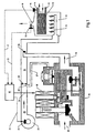
- the pressure of the compressed air generated by the blower 23 is fed via a pressure line 27 to the gas control device 10.
- a pressure line 27 to the gas control device 10.
- an aperture or throttle point 29 is arranged in the immediate vicinity of a connection region 28 of the pressure line 27.
- the controller 18 not only controls or regulates the power supply to the motor 22 of the fan 23, but also controls or regulates the power supply to a linear drive 30 of the gas control unit 10 and 10 in response to the signal 21 thus the amount of gas to be supplied to the burner 11.
- a corresponding control signal is the reference numeral 31 assigned.
- the signal 21 coming from the sensor 20 varies depending on the gas quality.
- the gas control device 10 consisting of a main gas valve 32, a safety valve 33 and a pressure regulator 34. Gas passes from a supply line, not shown, via an inlet 35 into the gas regulator 10 and leaves it through an outlet 36 to which, for example, the gas nozzle 26 is connected.
- the pressure regulator 34 has the already mentioned linear drive 30.
- a valve rod 37 which is displaceable via the linear drive 30, carries a closing body 38 at its lower end.
- An associated valve seat 39 is formed by a peripheral edge 40. Closing body 38 and valve seat 39 together form a switch-on valve 41.
- a first chamber 42 is arranged in the flow direction behind the switch-on valve 41.
- the chamber 42 is connected via a valve rod 37 surrounding channel 44 with a valve seat 45 in connection, which faces as a closing body of the central part 46 of a membrane 47.
- the valve rod 37 is held sealed in this central part 46 of the diaphragm 47.
- a second chamber 48 between membrane 47 and valve seat 45 is, as shown schematically in Fig. 2, connected to a channel 49.
- the channel 49 communicates with the outlet 36 of the gas control device 10 in connection.
- the gas control device can only be effective when the safety valve 33 is open. Construction and operation of such safety valves are known. In Fig. 2, all valves are shown in the rest position, in which they are held by return springs.
- the burner cycle can be started.
- the linear actuator 30 power is supplied, which causes the closing body 38 of the on-valve 41 is pressed down. If this current exceeds a minimum value, then the closing body 38 lifts off from the valve seat 39 and moves into an open position. With the opening of the on-valve 41, gas flows into the first chamber 42.
- the main gas valve 32 consisting of closure member 51, valve seat 52, valve rod 53, diaphragm 54 and the drive chamber 43 remains closed under the action of the return spring 55.
- the valve rod 37 is moved so far down that passes through the open switch-41 gas in the chamber 42, in which gradually builds up a control pressure. This is supplied via the channels 56 and 57 of the drive chamber 43 of the main valve 32.
- the force exerted on the diaphragm 54 by the control pressure in the drive chamber 43 the force exerted by the return spring 55, downwardly directed to the membrane 54 force plus the input pressure from above on the closing body 51 acting force exceeds the membrane moves 54, the valve rod 53 upwards and lifts the Closing member 51 from the valve seat 52. This allows gas from the inlet 35 through the space 50 and through the main gas valve 32 to the outlet 36th
- the control pressure which builds up in the second chamber 48 at the same time passes under the membrane 47 and holds there the equilibrium of the force exerted by the linear drive 30. If the pressure in the chamber 48 increases, the central part 46 of the diaphragm 47 which forms a closing body continues to lift away from the valve seat 45, so that a part of the control pressure in the chamber 48 is reduced via the channel 49 to the outlet 36 until the from the valve seat 45 and the central part 46 formed valve closes again. This happens as soon as the equilibrium of forces between the pneumatic force acting on the diaphragm 47 from below, of the pressure in the chamber 48, is equal to the force acting on the valve rod 37 from above.
- a constant pressure regulator 58 is present, which is connected via a channel 59 and the channel 56 to the control pressure leading chamber 42 and thus at the same time to the drive chamber 43 of the main valve 32. If the pressure in the channel 59 increases too much, it is blown off via the valve of the constant pressure regulator 58, consisting of the valve seat 60 and the closing body 61.
- a pressure chamber 62 of the constant pressure regulator 58 communicates via a channel 63 with the channel 49 leading to the outlet 36.
- the amount of pressure at the outlet 36 is determined by the balance of forces between the force acting on the diaphragm 64 of the constant pressure regulator 58 from below pneumatic force of the pressure in the drive chamber 43 and the forces acting from above on the membrane 64.
- the forces acting on the membrane 64 of the constant pressure regulator 58 from above are firstly the pneumatic force of the pressure in the air channel 25 and secondly a force acting on the membrane 64 via a spring 65.
- the spring force is adjustable.
- the adjustment of the equal pressure regulator 58 - also called 1: 1 gas / air regulator - takes place in relation to the worst expected (or in terms of the poorest) gas quality. The same applies to the design of the opening cross-sections of the gas nozzle 26 and throttle point 29. In the case of the worst or poorest gas quality of the linear actuator 30 of the pressure regulator 34, a maximum current I is further supplied.
- the gas regulator 10 operates like a 1: 1 gas / air regulator; the ratio of gas pressure to air pressure or the ratio of the burner 11 supplied gas flow and air flow is then 1: 1.
- Fig. 3 shows this relationship in the line 67, wherein the air pressure is plotted on the X-axis 68 and the gas pressure on the Y-axis 69.
- FIG. 3 shows this by way of example in the line 70 for the best expected (or for the richest) gas quality.
- the horizontal lines 71 in FIG. 3 correspond to a constant current I.
- the gas control device 10 To start up the burner 11, it is possible to proceed with the gas control device 10 according to the invention as follows: First, the blower 23 is started to provide an air flow. Subsequently, the safety valve 33 of the gas control device 10 is opened, wherein the maximum drive current I is supplied to the liner drive 30 of the pressure regulator 34, thus the gas control device 10 is operated during startup as a 1: 1 gas / air regulator. Gas flow and air flow are thus determined when starting the burner 11 in the ratio 1: 1, regardless of the actual gas quality. After ignition of the flame, the current I is reduced as a function of the actual gas quality. The gas / air flow is thus adapted to the gas quality.
- the gas flow rate to the burner 11 are increased, so the main gas valve 32 must be opened further, so the control pressure in the drive chamber 43 can be increased.
- the power supply to the fan 23 is increased via the controller 18, and on the other hand, the linear drive 30 is supplied with a stronger current. Due to the increased energy supply to the blower 23, the air pressure in the air duct 25 and thus the force acting from above on the diaphragm 64 of the constant pressure regulator 58 increases. Due to the increased power supply to the linear actuator 30, the valve rod 37 is pressed with greater force down. The valve formed from the valve seat 45 and the central part 46 then opens only at a higher pressure under the membrane 47. When a desired reduction in the gas flow rate to the burner 11 is reversed.
- linear drive 30 e.g. a magnetic drive with fixed coil and movable armature or a Tauchspulantrieb with fixed magnetic circuit and movable coil use find.
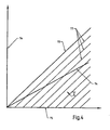
- Fig. 4 shows the functional dependence between air flow and gas flow at different gas qualities again.
- Line 73 in Fig. 4 shows the ratio of gas pressure to air pressure or the ratio of the gas flow supplied to the burner 11 and air flow for the worst (poorest) expected gas quality.
- the air pressure is plotted on the x-axis 75 and the gas pressure on the y-axis 76.
- the linear actuator 30 of the pressure regulator 34 again a maximum current I is supplied.
- the gas regulator then works like a 1: 1 gas / air regulator. With an improved gas quality detected via the sensor 20, the current I supplied to the linear drive 30 of the pressure regulator 34 is reduced via the temperature regulator 18. The gas stream then decreases in proportion to the air flow.
- the constant pressure regulator 58 or the 1: 1 gas / air regulator of the gas control devices of the embodiments described above can be replaced by a ratio pressure regulator or a 1: N gas / air regulator.
Landscapes
- Engineering & Computer Science (AREA)
- Chemical & Material Sciences (AREA)
- Combustion & Propulsion (AREA)
- Mechanical Engineering (AREA)
- General Engineering & Computer Science (AREA)
- Regulation And Control Of Combustion (AREA)
Claims (4)
- Régulateur pour brûleurs à gaz destiné à fournir un mélange gaz/air optimisé pour la combustion et tenant compte de qualités de gaz différentes, comprenant une soupape à gaz principale (32), une soupape de sûreté (33), un premier régulateur de pression (34) pour régler le flux de gaz et un second régulateur de pression (58) qui limite la pression maximale autorisée du flux de gaz à amener dans un brûleur (11) à la pression du flux d'air à amener également dans le brûleur (11) et dans lequel est amenée la pression du flux d'air,
caractérisé en ce que la pression initiale du premier régulateur de pression (34) est réglable grâce à un entraînement linéaire, la pression du flux d'air étant amenée en supplément dans le premier régulateur de pression (34) afin de modifier, grâce au réglage de la pression de commande initiale du premier régulateur de pression (34), le flux de gaz tout en conservant le flux d'air. - Régulateur selon la revendication 1, caractérisé en ce que la pression du flux d'air peut être amenée dans le second régulateur de pression (58) par l'intermédiaire d'une conduite de pression (27).
- Régulateur selon la revendication 1 ou 2, caractérisé en ce que le second régulateur de pression (58) est conçu comme un équilibreur.
- Régulateur selon la revendication 1 ou 2, caractérisé en ce que le second régulateur de pression (58) est conçu comme un régulateur de pression à fonction proportionnelle.
Applications Claiming Priority (2)
| Application Number | Priority Date | Filing Date | Title |
|---|---|---|---|
| DE19821853A DE19821853C1 (de) | 1998-05-15 | 1998-05-15 | Regeleinrichtung für Gasbrenner |
| DE19821853 | 1998-05-15 |
Publications (3)
| Publication Number | Publication Date |
|---|---|
| EP0957314A2 EP0957314A2 (fr) | 1999-11-17 |
| EP0957314A3 EP0957314A3 (fr) | 2002-03-13 |
| EP0957314B1 true EP0957314B1 (fr) | 2006-01-04 |
Family
ID=7867896
Family Applications (1)
| Application Number | Title | Priority Date | Filing Date |
|---|---|---|---|
| EP99109002A Expired - Lifetime EP0957314B1 (fr) | 1998-05-15 | 1999-05-06 | Dispositif de commande pour des brûleurs à gaz |
Country Status (2)
| Country | Link |
|---|---|
| EP (1) | EP0957314B1 (fr) |
| DE (2) | DE19821853C1 (fr) |
Cited By (1)
| Publication number | Priority date | Publication date | Assignee | Title |
|---|---|---|---|---|
| CN111075984A (zh) * | 2020-01-14 | 2020-04-28 | 嘉兴市大宇机电有限公司 | 一种校零空燃比例电磁阀 |
Families Citing this family (19)
| Publication number | Priority date | Publication date | Assignee | Title |
|---|---|---|---|---|
| AT408271B (de) * | 1999-05-25 | 2001-10-25 | Vaillant Gmbh | Einrichtung zur einstellung der gasart für eine heizeinrichtung |
| DE10017990C2 (de) * | 2000-04-11 | 2002-03-07 | Viessmann Werke Kg | Gasgebläsebrenner |
| DE10022882B4 (de) * | 2000-05-10 | 2010-04-29 | Loi Thermprocess Gmbh | Verfahren und Vorrichtung zum Regeln eines Brenners |
| DE10026035C2 (de) * | 2000-05-25 | 2002-06-27 | Honeywell Bv | Regeleinrichtung für Gasbrenner |
| DE10209193C1 (de) * | 2002-03-04 | 2003-11-20 | Heatec Thermotechnik Gmbh | Elektrisch steuerbares Gasventil |
| DE10232647B4 (de) | 2002-07-18 | 2004-05-13 | Honeywell B.V. | Regeleinrichtung für Gasbrenner |
| DE10232654B3 (de) | 2002-07-18 | 2004-03-11 | Honeywell B.V. | Gasdurchflussregeleinrichtung |
| DE10232653B3 (de) | 2002-07-18 | 2004-03-11 | Honeywell B.V. | Regeleinrichtung für Gasbrenner |
| WO2005073632A1 (fr) * | 2004-01-28 | 2005-08-11 | Sit La Precisa S.P.A. | Unite de soupape multifonction controlant la fourniture de gaz combustible a un bruleur |
| JP4790397B2 (ja) * | 2005-12-05 | 2011-10-12 | タイム技研株式会社 | ガバナ装置 |
| DE102006036294A1 (de) * | 2006-08-03 | 2008-02-07 | Inter Control Hermann Köhler Elektrik GmbH & Co. KG | Gasventil und Verfahren zur Ansteuerung eines Gasventils |
| US7950622B2 (en) | 2007-07-25 | 2011-05-31 | Honeywell International, Inc. | System, apparatus and method for controlling valves |
| DE102008024843A1 (de) | 2008-05-23 | 2009-11-26 | Honeywell Technologies S.A.R.L. | Gasregelgerät |
| DE202010015938U1 (de) | 2010-11-30 | 2011-02-10 | Honeywell Technologies Sarl | Gasregelgerät |
| DE102013003524B4 (de) | 2013-03-04 | 2022-07-14 | Pittway Sàrl | Gasregelgerät |
| EP2868970B1 (fr) | 2013-10-29 | 2020-04-22 | Honeywell Technologies Sarl | Dispositif de régulation |
| DE102017222437A1 (de) * | 2017-12-12 | 2019-06-13 | Robert Bosch Gmbh | Heizgerätkomponente und Verfahren zur Einstellung eines Brennstoffvolumenstroms |
| DE102018121844A1 (de) | 2018-09-07 | 2020-03-12 | Vaillant Gmbh | Gasventil |
| EP4302015A1 (fr) | 2021-03-04 | 2024-01-10 | Pittway Sarl | Appareil de type brûleur à gaz partiellement prémélangé |
Family Cites Families (5)
| Publication number | Priority date | Publication date | Assignee | Title |
|---|---|---|---|---|
| EP0103303A3 (fr) * | 1982-09-15 | 1984-06-06 | Joh. Vaillant GmbH u. Co. | Source de chaleur chauffée au combustible |
| DE3911268A1 (de) * | 1989-04-07 | 1990-10-11 | Honeywell Bv | Regeleinrichtung fuer gasbrenner |
| AT396850B (de) * | 1991-09-09 | 1993-12-27 | Vaillant Gmbh | Servodruckregler |
| DE4343306A1 (de) * | 1993-12-17 | 1995-06-22 | Gastechnic Prod Vertriebges | Verfahren und Vorrichtung zur Regelung des Druckes in einer Gasleitung |
| IT1274622B (it) * | 1994-08-17 | 1997-07-18 | Integra Srl | Gruppo valvolare per caldaie a gas |
-
1998
- 1998-05-15 DE DE19821853A patent/DE19821853C1/de not_active Expired - Lifetime
-
1999
- 1999-05-06 EP EP99109002A patent/EP0957314B1/fr not_active Expired - Lifetime
- 1999-05-06 DE DE59913006T patent/DE59913006D1/de not_active Expired - Lifetime
Cited By (2)
| Publication number | Priority date | Publication date | Assignee | Title |
|---|---|---|---|---|
| CN111075984A (zh) * | 2020-01-14 | 2020-04-28 | 嘉兴市大宇机电有限公司 | 一种校零空燃比例电磁阀 |
| CN111075984B (zh) * | 2020-01-14 | 2022-02-22 | 嘉兴市大宇机电有限公司 | 一种校零空燃比例电磁阀 |
Also Published As
| Publication number | Publication date |
|---|---|
| EP0957314A2 (fr) | 1999-11-17 |
| EP0957314A3 (fr) | 2002-03-13 |
| DE59913006D1 (de) | 2006-03-30 |
| DE19821853C1 (de) | 1999-07-29 |
Similar Documents
| Publication | Publication Date | Title |
|---|---|---|
| EP0957314B1 (fr) | Dispositif de commande pour des brûleurs à gaz | |
| EP0644377B1 (fr) | Dispositif de commande pour brûleur à gaz | |
| DE19515286C2 (de) | Druckregler zum Erzeugen eines geregelten Steuerdrucks für ein membrangesteuertes Gasventil | |
| EP0062854B1 (fr) | Dispositif de chauffage à gaz pour eau ou air | |
| DE3026190A1 (de) | Heizeinrichtung | |
| DE2649665A1 (de) | Langsam oeffnendes gasventil | |
| EP0907052A2 (fr) | Dispositif de commande de rapport pneumatique | |
| EP0390964B1 (fr) | Dispositif de commande pour brûleur à gaz | |
| EP1635066B1 (fr) | Installation d'alimentation en gaz et procédé d'utilisation associé pour une turbine à gaz | |
| DE102019101357B4 (de) | Anordnung zum zweistufigen Lufteinlassen und -auslassen für elektrisch gesteuerte Proportionalventile | |
| EP0062856B1 (fr) | Dispositif de régulation pour une chaudière à gaz d'une installation de chauffage à eau chaude | |
| DE19501749C2 (de) | Verfahren und Vorrichtung zum Steuern eines Gas-Gebläsebrenners | |
| EP0103303A2 (fr) | Source de chaleur chauffée au combustible | |
| EP0035147B1 (fr) | Régulateur de pression à gaz | |
| EP0036613B1 (fr) | Dispositif de régulation pour un échauffeur à eau ou air à combustion gazeuse pouvant être commandé par un capteur de température | |
| EP0036610B1 (fr) | Procédé de fonctionnement d'une source de chaleur chauffée par combustible | |
| EP0016326A1 (fr) | Régulateur de pression du gaz | |
| EP0108349A2 (fr) | Source de chaleur chauffée au gaz | |
| DE3007214C2 (de) | Gasdruckregler für einen gasbeheizten Umlaufwasserheizer mit einem Gebrauchswasserbereiter | |
| EP0109978A1 (fr) | Appareil de régulation de gaz avec un servorégulateur de pression | |
| DE3333606A1 (de) | Brennstoffbeheizte waermequelle | |
| EP0617240B1 (fr) | Chaudière mixte | |
| EP0206132A2 (fr) | Interrupteur commandé en fonction de la pression | |
| DE3010737A1 (de) | Gasregelgeraet fuer brenner | |
| EP1305553A1 (fr) | Systeme de combustion pour un appareil de cuisson et appareil de cuisson pourvu d'un tel systeme de combustion |
Legal Events
| Date | Code | Title | Description |
|---|---|---|---|
| PUAI | Public reference made under article 153(3) epc to a published international application that has entered the european phase |
Free format text: ORIGINAL CODE: 0009012 |
|
| AK | Designated contracting states |
Kind code of ref document: A2 Designated state(s): AT BE CH CY DE DK ES FI FR GB GR IE IT LI LU MC NL PT SE Kind code of ref document: A2 Designated state(s): DE FR GB IT NL |
|
| AX | Request for extension of the european patent |
Free format text: AL;LT;LV;MK;RO;SI |
|
| PUAL | Search report despatched |
Free format text: ORIGINAL CODE: 0009013 |
|
| AK | Designated contracting states |
Kind code of ref document: A3 Designated state(s): AT BE CH CY DE DK ES FI FR GB GR IE IT LI LU MC NL PT SE |
|
| AX | Request for extension of the european patent |
Free format text: AL;LT;LV;MK;RO;SI |
|
| RIC1 | Information provided on ipc code assigned before grant |
Free format text: 7F 23N 1/02 A, 7F 23N 5/18 B |
|
| 17P | Request for examination filed |
Effective date: 20020522 |
|
| AKX | Designation fees paid |
Free format text: DE FR GB IT NL |
|
| 17Q | First examination report despatched |
Effective date: 20040326 |
|
| GRAP | Despatch of communication of intention to grant a patent |
Free format text: ORIGINAL CODE: EPIDOSNIGR1 |
|
| GRAS | Grant fee paid |
Free format text: ORIGINAL CODE: EPIDOSNIGR3 |
|
| GRAA | (expected) grant |
Free format text: ORIGINAL CODE: 0009210 |
|
| AK | Designated contracting states |
Kind code of ref document: B1 Designated state(s): DE FR GB IT NL |
|
| REG | Reference to a national code |
Ref country code: GB Ref legal event code: FG4D Free format text: NOT ENGLISH |
|
| GBT | Gb: translation of ep patent filed (gb section 77(6)(a)/1977) |
Effective date: 20060104 |
|
| REF | Corresponds to: |
Ref document number: 59913006 Country of ref document: DE Date of ref document: 20060330 Kind code of ref document: P |
|
| ET | Fr: translation filed | ||
| PLBE | No opposition filed within time limit |
Free format text: ORIGINAL CODE: 0009261 |
|
| STAA | Information on the status of an ep patent application or granted ep patent |
Free format text: STATUS: NO OPPOSITION FILED WITHIN TIME LIMIT |
|
| 26N | No opposition filed |
Effective date: 20061005 |
|
| REG | Reference to a national code |
Ref country code: GB Ref legal event code: 732E |
|
| NLS | Nl: assignments of ep-patents |
Owner name: HONEYWELL TECHNOLOGIES SARL Effective date: 20080618 |
|
| REG | Reference to a national code |
Ref country code: FR Ref legal event code: TP |
|
| PGFP | Annual fee paid to national office [announced via postgrant information from national office to epo] |
Ref country code: NL Payment date: 20120515 Year of fee payment: 14 Ref country code: DE Payment date: 20120531 Year of fee payment: 14 |
|
| PGFP | Annual fee paid to national office [announced via postgrant information from national office to epo] |
Ref country code: GB Payment date: 20120426 Year of fee payment: 14 Ref country code: FR Payment date: 20120510 Year of fee payment: 14 |
|
| PGFP | Annual fee paid to national office [announced via postgrant information from national office to epo] |
Ref country code: IT Payment date: 20120518 Year of fee payment: 14 |
|
| REG | Reference to a national code |
Ref country code: NL Ref legal event code: V1 Effective date: 20131201 |
|
| GBPC | Gb: european patent ceased through non-payment of renewal fee |
Effective date: 20130506 |
|
| PG25 | Lapsed in a contracting state [announced via postgrant information from national office to epo] |
Ref country code: DE Free format text: LAPSE BECAUSE OF NON-PAYMENT OF DUE FEES Effective date: 20131203 |
|
| PG25 | Lapsed in a contracting state [announced via postgrant information from national office to epo] |
Ref country code: IT Free format text: LAPSE BECAUSE OF NON-PAYMENT OF DUE FEES Effective date: 20130506 Ref country code: NL Free format text: LAPSE BECAUSE OF NON-PAYMENT OF DUE FEES Effective date: 20131201 |
|
| REG | Reference to a national code |
Ref country code: DE Ref legal event code: R119 Ref document number: 59913006 Country of ref document: DE Effective date: 20131203 |
|
| REG | Reference to a national code |
Ref country code: FR Ref legal event code: ST Effective date: 20140131 |
|
| PG25 | Lapsed in a contracting state [announced via postgrant information from national office to epo] |
Ref country code: GB Free format text: LAPSE BECAUSE OF NON-PAYMENT OF DUE FEES Effective date: 20130506 |
|
| PG25 | Lapsed in a contracting state [announced via postgrant information from national office to epo] |
Ref country code: FR Free format text: LAPSE BECAUSE OF NON-PAYMENT OF DUE FEES Effective date: 20130531 |