EP0907052A2 - Pneumatic ratio controller - Google Patents
Pneumatic ratio controller Download PDFInfo
- Publication number
- EP0907052A2 EP0907052A2 EP98113154A EP98113154A EP0907052A2 EP 0907052 A2 EP0907052 A2 EP 0907052A2 EP 98113154 A EP98113154 A EP 98113154A EP 98113154 A EP98113154 A EP 98113154A EP 0907052 A2 EP0907052 A2 EP 0907052A2
- Authority
- EP
- European Patent Office
- Prior art keywords
- pressure
- pressure regulator
- control device
- fluid
- ratio
- Prior art date
- Legal status (The legal status is an assumption and is not a legal conclusion. Google has not performed a legal analysis and makes no representation as to the accuracy of the status listed.)
- Withdrawn
Links
Images

Classifications
-
- G—PHYSICS
- G05—CONTROLLING; REGULATING
- G05D—SYSTEMS FOR CONTROLLING OR REGULATING NON-ELECTRIC VARIABLES
- G05D16/00—Control of fluid pressure
- G05D16/14—Control of fluid pressure with auxiliary non-electric power
- G05D16/16—Control of fluid pressure with auxiliary non-electric power derived from the controlled fluid
- G05D16/163—Control of fluid pressure with auxiliary non-electric power derived from the controlled fluid using membranes within the main valve
-
- F—MECHANICAL ENGINEERING; LIGHTING; HEATING; WEAPONS; BLASTING
- F23—COMBUSTION APPARATUS; COMBUSTION PROCESSES
- F23D—BURNERS
- F23D14/00—Burners for combustion of a gas, e.g. of a gas stored under pressure as a liquid
- F23D14/46—Details
- F23D14/60—Devices for simultaneous control of gas and combustion air
-
- F—MECHANICAL ENGINEERING; LIGHTING; HEATING; WEAPONS; BLASTING
- F23—COMBUSTION APPARATUS; COMBUSTION PROCESSES
- F23N—REGULATING OR CONTROLLING COMBUSTION
- F23N1/00—Regulating fuel supply
- F23N1/02—Regulating fuel supply conjointly with air supply
- F23N1/027—Regulating fuel supply conjointly with air supply using mechanical means
-
- F—MECHANICAL ENGINEERING; LIGHTING; HEATING; WEAPONS; BLASTING
- F23—COMBUSTION APPARATUS; COMBUSTION PROCESSES
- F23N—REGULATING OR CONTROLLING COMBUSTION
- F23N2225/00—Measuring
- F23N2225/04—Measuring pressure
-
- F—MECHANICAL ENGINEERING; LIGHTING; HEATING; WEAPONS; BLASTING
- F23—COMBUSTION APPARATUS; COMBUSTION PROCESSES
- F23N—REGULATING OR CONTROLLING COMBUSTION
- F23N2235/00—Valves, nozzles or pumps
- F23N2235/12—Fuel valves
- F23N2235/20—Membrane valves
Definitions
- the invention relates to a control device for compliance an at least almost always the same relationship between the pressure of a first, in particular gaseous Fluids, preferably a fuel gas, and the pressure of a second, in particular gaseous fluids, preferably from Air, shortly before it is brought together in a mixing room, preferably in a firebox of a gas burner independently of that in the mixing room opposite the pressures of the two Fluid prevailing negative pressure, with one in the mixing space leading main line for the first fluid and with a Pressure regulator of the one in the main line Inlet pressure of the first fluid depending on the required Pressure ratio.
- a first in particular gaseous Fluids
- a second, in particular gaseous fluids preferably from Air
- Such an adjusting device is e.g. through the DE 25 47 075 C3 has become known.
- Gas firing systems that ensure that the gas / air pressure ratio of one for an optimal combustion desired value in the entire performance range the gas burner system as little as possible deviates.
- the amount of gas / air mixture supplied to the gas firing depends on the currently required Heating output that can fluctuate in large areas.
- the so-called “pneumatic Compound regulator” the pressure of the gas based on the pressure loss changed at a throttle to always do that to achieve the same mixing ratio.
- To build relationships are usually two membranes and a comparative balance lever needed.
- Common to all pneumatic compound controllers also the possibility of considering the Press in the combustion chamber of the gas burner system so that the the mass flow from the burner into the combustion chamber is crucial Pressure difference in the gas mixture composition taken into account can be.
- the present invention has the object based on a control device of the type mentioned to further develop that the desired always the same Pressure ratio between the first fluid (fuel gas) and the second fluid (air) just before the common mixing room (Combustion chamber) as simple as possible and with few components can be adjusted.
- This control device allows inexpensive metering of the fuel gas in almost always the correct ratio to incoming combustion air in gas burners or in general for devices or machines that consist of a certain mixture need a first and a second fluid.
- This control device enables this correct metering in one large operating load range in a non-mechanical manner few components and with a particularly small installation space.
- the regulated pressure of the first fluid flows through the two Throttles (e.g. nozzles) in the mixing room.
- Throttles e.g. nozzles
- the fluid pressure prevailing upstream of the control element reduced in the desired ratio as a control variable the pressure regulator.
- the pressure regulator does not regulate how usual - e.g. to zero pressure, but to a higher one Pressure caused by the ratio of pressure drops to the two throttles is determined.
- the Throttle cross sections is the desired pressure ratio determined both fluids.
- the ratio of the throttle cross sections of the two throttles arranged one behind the other can be changed in order to same control device on another if necessary to be able to adjust the pressure ratio of the two fluids.
- chokes with different cross sections be interchangeable.
- throttle cross section of at least one throttle continuously adjustable to the pressure ratio within to be able to set certain limits as desired.
- continuous acting throttle can e.g. one in the flow cross section screw-in set screw may be provided.
- the throttle cross section of at least one Throttle also by connecting or switching one or more other chokes can be changed.
- the Pressure regulator on a control membrane, one side of which with the reduced pressure of the first fluid and its other side is acted upon by the pressure of the second fluid, so that the control element of the pressure regulator the pressure of the first Fluids corresponding to the pressure difference between the reduced Pressure of the first fluid and the pressure of the second Fluid sets.
- Control element of the pressure regulator that adjusts the inlet pressure are in drive connection with the control diaphragm.
- actuator and control diaphragm rigid with each other be connected.
- the control element of the pressure regulator is preferably opposed gravity and upstream inlet pressure of the first fluid, in particular spring-loaded, so that according to the over the throttle cross sections set pressure ratio a resulting A force acts which controls the first fluid flow Actuator only against e.g. the power of a spring more or less wide opens.
- the pressure regulator is a zero pressure regulator.
- starting point can be a conventional zero pressure regulator, its pressure measuring point not directly at the exit of the first, as usual Fluid is, but the pressure of the first fluid reaches reduced in the desired ratio by the first throttle as a controlled variable to the pressure regulator.
- the zero pressure regulator preferably has a zero pressure adjustment on.
- a spring preload on the pressure regulator can be a performance-related change the mixing ratio can be achieved. It affects prefers the lower power range.
- the pressure regulator can also be designed as a servo pressure regulator be. This can be the upstream of the bypass line prevailing input pressure adjusting actuator of Servo controller over the first fluid according to the difference between the reduced pressure of the first fluid and the Pressure of the second fluid are operated.
- the chokes can, especially with new devices, already in the pressure regulator can be integrated, or in a separate one Throttle part can be provided, which to a conventional Pressure regulator can be connected.
- the invention also relates to a separate throttle part at least two chokes arranged one behind the other for the Control device described above, wherein the throttle part a conventional pressure regulator can be connected.
- the Throttle part becomes the pressure measuring point of the first fluid e.g. not as usual with a conventional zero pressure regulator directly pressurized with the first fluid is reduced in the desired ratio by the first throttle passed to the actuator of the pressure regulator.
- the gas pressure regulator does not regulate to zero pressure, as usual, but to a higher pressure caused by the ratio the pressure loss at the two throttles is determined.
- This Throttle part can the adjustable, described above, have interchangeable or switchable or connectable chokes.
- FIG. 1, 1 denotes a control device according to the invention for automatically setting the correct pressure ratio between a fuel gas (first fluid ) 2 and air (second fluid) 3 , shortly before it is introduced separately into a common combustion chamber (mixing chamber) 4 of a gas burner 5 will.
- the fuel gas 2 supplied via a gas line 6 flows into a main line 8 , from which it exits into the combustion chamber 4 via a gas nozzle 9 .
- a negative pressure (combustion chamber back pressure) p F is generated by means of a fan 10 , so that the fuel gas 2 and atmospheric air 3 are sucked in.
- the power of the gas burner 5 is set by different speeds of the fan motor, ie by a changed vacuum p F.
- the fuel gas pressure p Br prevailing in the main line 8 in front of the gas nozzle 9 can be set via an adjusting element 11 in the main line 8, which is part of a pressure regulator 12 .
- a bypass line 13 branches off from the main line 8 between the control element 11 and the gas nozzle 9 and also leads into the combustion chamber 4.
- two throttles 14 and 15 are arranged one behind the other, between which there is a reduced fuel gas pressure p red .
- This reduced fuel gas pressure p red is fed via a line 16 located between the throttles 14, 15 to the pressure regulator 12 as a controlled variable which, according to the pressure ratio p L / p Br, between the air pressure p L at the gas burner 5 and the reduced fuel gas pressure p red via the control element 11, for example via a gas valve, adjusts the fuel gas pressure p Br in the main line 8.
- control element 11 is in drive connection with a control membrane 17 in the pressure regulator 12, on one side of which the reduced fuel gas pressure p red and on the other side of which the air pressure p L acts.
- a restoring force of the control membrane 17 can be adjusted by changing the pretension of a spring 18 which acts on the control membrane 17 (zero pressure adjustment).
- the pressure regulator 12 is set to approximately zero pressure, so that the actuating element 11 is actuated only pneumatically by the applied pressures, p L and p red . That is, the control element 11 is opened or closed until a pressure difference no longer acts on the control diaphragm 17.
- n indicates the cross-sectional ratio between the first throttle 14 and the second throttle 15.
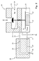
- FIG. 2 shows a conventional zero pressure regulator 20 , the control membrane 21 of which is not, as usual, with the gas pressure p Br prevailing in the main line 23 downstream of the control element 22 , but via the bypass line 24 with the ratio reduced by the two throttles 25 , 26 in the desired ratio Gas pressure p red is applied.
- the air pressure p L acts on the other side of the control membrane 21, and the actuating element 22 is rigidly connected to a membrane plate 27 of the control membrane 21.
- the throttles 25, 26 are provided in a separate throttle part 28 , the bypass line 24 and the line 29 of the throttle part 28 being connected to corresponding external connections 30 , 31 of the zero pressure regulator 20.
- a spring 32 acting on the diaphragm plate 27 serves to compensate for gravity and the upstream gas inlet pressure acting on the actuating element 22.
- this zero pressure regulator 20 does not regulate as usual at zero pressure, but at a higher pressure, which is due to the ratio of pressure drops across the two Chokes 25, 26 is determined.
- the pressure ratio can be variable be by different chokes or an adjustable Choke can be used.
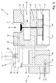
- FIG. 3 shows a servo pressure regulator 40 with a control diaphragm 41 , the lower working chamber 42 of which is not, as usual, with the gas pressure p Br prevailing in the main line 44 downstream of the actuating element 43 , but via the bypass line 45 with that through the two throttles 46 , 47 reduced gas pressure p red is applied in the desired ratio.
- the air pressure p L acts on the other side of the control diaphragm 41.
- a diaphragm plate 48 connected to the control diaphragm 41 controls the outflow of the fuel gas within a servo line 50 opening into the lower working space 42 in accordance with the ratio p red / p L and the prestress by the spring 49 .
- this servo pressure regulator 40 also regulates not to zero pressure as usual, but to a higher one Pressure caused by the ratio of pressure drops to the two throttles 46, 47 is determined.
- Adjusting screw trained second throttle 47 is the throttle cross section continuously adjustable and thus that Pressure ratio adjustable within certain limits.
Landscapes
- Engineering & Computer Science (AREA)
- Chemical & Material Sciences (AREA)
- Combustion & Propulsion (AREA)
- Mechanical Engineering (AREA)
- General Engineering & Computer Science (AREA)
- Physics & Mathematics (AREA)
- Power Engineering (AREA)
- Fluid Mechanics (AREA)
- General Physics & Mathematics (AREA)
- Automation & Control Theory (AREA)
- Control Of Fluid Pressure (AREA)
- Regulation And Control Of Combustion (AREA)
Abstract
Bei einer Regelvorrichtung (1) für das Einhalten eines zumindest nahezu stets gleichen Verhältnisses ((pBr-pF)/(pL- pF)) zwischen dem Druck (pbr) eines ersten, insbesondere gasförmigen Fluids, vorzugsweise eines Brenngases (2), und dem Druck (pL) eines zweiten, insbesondere gasförmigen Fluids, vorzugsweise von Luft (3), kurz vor ihrer Zusammenführung in einen Mischungsraum, vorzugsweise in einen Feuerraum (4) eines Gasbrenners (5), unabhängig von dem im Mischungsraum gegenüber den Drücken (pBr, pL) der beiden Fluide herrschenden Unterdruck (pF), mit einer in den Mischungsraum führenden Hauptleitung (8) für das erste Fluid und mit einem Druckregler (12), der den in der Hauptleitung (8) herrschenden Eingangsdruck des ersten Fluids in Abhängigkeit des geforderten Druckverhältnisses einstellt, ist von der Hauptleitung (8) stromabwärts eines Stellelements (11) des Druckreglers (12) eine ebenfalls in den Mischungsraum führende Bypassleitung (13) mit zwei hintereinander angeordneten Drosseln (14, 15) abgezweigt, wobei der zwischen den zwei hintereinander angeordneten Drosseln (14, 15) herrschende, reduzierte Druck (pred) des ersten Fluids dem Druckregler (12) als Regelgröße zugeführt wird. Diese Regelvorrichtung ermöglicht eine korrekte Zumessung in einem großen Betriebslastbereich auf nichtmechanische Weise mit wenigen Bauteilen und bei besonders kleinem Bauraum. <IMAGE>In a control device (1) for maintaining an at least almost always the same ratio ((pBr-pF) / (pL-pF)) between the pressure (pbr) of a first, in particular gaseous fluid, preferably a fuel gas (2), and the Pressure (pL) of a second, in particular gaseous, fluid, preferably air (3), shortly before it is brought together in a mixing chamber, preferably in a combustion chamber (4) of a gas burner (5), regardless of the pressure (pBr, pL) of the two fluids negative pressure (pF), with a main line (8) leading into the mixing chamber for the first fluid and with a pressure regulator (12) which determines the inlet pressure of the first fluid in the main line (8) depending on the required If the pressure ratio is set, a bypass line (13), which also leads into the mixing chamber and has two in a row, is arranged downstream of an adjusting element (11) of the pressure regulator (12) from the main line (8) eten throttles (14, 15) branched off, the reduced pressure (pred) of the first fluid prevailing between the two throttles (14, 15) arranged one behind the other being fed to the pressure regulator (12) as a controlled variable. This control device enables correct metering in a large operating load range in a non-mechanical manner with few components and with a particularly small installation space. <IMAGE>
Description
Die Erfindung betrifft eine Regelvorrichtung für das Einhalten eines zumindest nahezu stets gleichen Verhältnisses zwischen dem Druck eines ersten, insbesondere gasförmigen Fluids, vorzugsweise eines Brenngases, und dem Druck eines zweiten, insbesondere gasförmigen Fluids, vorzugsweise von Luft, kurz vor ihrer Zusammenführung in einen Mischungsraum, vorzugsweise in einen Feuerraum eines Gasbrenners unabhängig von dem im Mischungsraum gegenüber den Drücken der beiden Fluide herrschenden Unterdruck, mit einer in den Mischungsraum führenden Hauptleitung für das erste Fluid und mit einem Druckregler, der den in der Hauptleitung herrschenden Eingangsdruck des ersten Fluids in Abhängigkeit des geforderten Druckverhältnisses einstellt. The invention relates to a control device for compliance an at least almost always the same relationship between the pressure of a first, in particular gaseous Fluids, preferably a fuel gas, and the pressure of a second, in particular gaseous fluids, preferably from Air, shortly before it is brought together in a mixing room, preferably in a firebox of a gas burner independently of that in the mixing room opposite the pressures of the two Fluid prevailing negative pressure, with one in the mixing space leading main line for the first fluid and with a Pressure regulator of the one in the main line Inlet pressure of the first fluid depending on the required Pressure ratio.
Eine derartige Einstellvorrichtung ist z.B. durch die
DE 25 47 075 C3 bekanntgeworden.Such an adjusting device is e.g. through the
Zur Regelung der Brenngas- und Verbrennungsluftzufuhr zu Gasfeuerungsanlagen sind Gas/Luft-Verbundregler bekannt, die dafür sorgen, daß das Gas/Luft-Druckverhältnis von einem für eine optimale Verbrennung gewünschten Wert im gesamten Leistungsbereich der Gasfeuerungsanlage so wenig wie möglich abweicht. Die Menge des der Gasfeuerung zugeführten Gas/Luft-Gemisches hängt von der jeweils gerade geforderten Heizleistung ab, die in großen Bereichen schwanken kann.To regulate the fuel gas and combustion air supply too Gas firing systems are known gas / air composite controllers that ensure that the gas / air pressure ratio of one for an optimal combustion desired value in the entire performance range the gas burner system as little as possible deviates. The amount of gas / air mixture supplied to the gas firing depends on the currently required Heating output that can fluctuate in large areas.
Es sind bereits Verbundregler bekannt, bei denen sich die Gaszumessung nach dem Druckverlust an einer Drosselstelle richtet.Compound controllers are already known in which the Gas metering after the pressure loss at a throttle point judges.
Beim sogenannten "mechanischen Gas-Luftverbund" werden, um die Leistung zu verändern, die Querschnitte von Gas und Luft gleichermaßen verändert. Nachteilig daran ist allerdings der große technische Aufwand.In the so-called "mechanical gas-air network", in order to change the performance, the cross sections of gas and air alike changed. The disadvantage of this, however, is that great technical effort.
Bei der sogenannten "Nulldruckregelung" wird der Druckverlust an einer Gasdüse in etwa gleich gewählt wie der Druckverlust an einer Luftdüse. Dadurch wird das Mischungsverhältnis unabhängig vom Durchsatz. Allerdings muß hier der Gasdruck recht niedrig gewählt werden, was zu größeren Ungenauigkeiten und zu einem kleinen Leistungsbereich führt.With the so-called "zero pressure control" the pressure loss selected at a gas nozzle approximately the same as the pressure loss on an air nozzle. This will make the mix ratio regardless of throughput. However, here the Gas pressure can be chosen quite low, leading to greater inaccuracies and leads to a small performance range.
Um die Leistung zu verändern, wird beim sogenannten "pneumatischen Verbundregler" der Druck des Gases anhand des Druckverlustes an einer Drosselstelle verändert, um stets das gleiche Mischungsverhältnis zu erreichen. Zur Verhältnisbildung werden in der Regel zwei Membranen und ein Vergleichs-Waagehebel benötigt. Gemeinsam ist allen pneumatischen Verbundreglern auch die Möglichkeit der Berücksichtigung der Drücke im Feuerraum der Gasfeuerungsanlage, so daß die für den Massestrom vom Brenner in den Feuerraum ausschlaggebende Druckdifferenz bei der Gasgemischzusammensetzung berücksichtigt werden kann.To change the performance, the so-called "pneumatic Compound regulator "the pressure of the gas based on the pressure loss changed at a throttle to always do that to achieve the same mixing ratio. To build relationships are usually two membranes and a comparative balance lever needed. Common to all pneumatic compound controllers also the possibility of considering the Press in the combustion chamber of the gas burner system so that the the mass flow from the burner into the combustion chamber is crucial Pressure difference in the gas mixture composition taken into account can be.
Die Wirkungsweise eines derartigen pneumatischen Verbundreglers,
wie sie beispielsweise aus der eingangs genannten
DE 25 47 075 C3 bekannt ist, basiert auf der Gleichgewichtsbildung
zwischen den beiden Momenten der Kräfte an der Luftmembran
mal Hebelarm der Luftseite und der Kräfte an der
Gasmembran mal Hebelarm der Gasseite eines Waagehebels, wobei
sowohl der Luftmembran als auch der Gasmembran der Druck
im Feuerraum entgegenwirkt. Entsprechend der Stellung des
Waagehebels wird mittels eines in der Gasleitung vorgesehenen
Gasventils die Gaszufuhr eingestellt. Durch Verstellen
des Auflagepunkts des Waagebalkens längs des Waagebalkens
läßt sich das Gas/Luft-Druckverhältnis mechanisch einstellen,
was konstruktiv sehr aufwendig ist.The mode of operation of such a pneumatic compound controller,
as for example from the
Der vorliegenden Erfindung liegt demgegenüber die Aufgabe zugrunde, eine Regelvorrichtung der eingangs genannten Art dahingehend weiterzubilden, daß das gewünschte stets gleiche Druckverhältnis zwischen dem ersten Fluid (Brenngas) und dem zweiten Fluid (Luft) kurz vor dem gemeinsamen Mischungsraum (Feuerraum) möglichst einfach und mit wenigen Bauteilen eingestellt werden kann.In contrast, the present invention has the object based on a control device of the type mentioned to further develop that the desired always the same Pressure ratio between the first fluid (fuel gas) and the second fluid (air) just before the common mixing room (Combustion chamber) as simple as possible and with few components can be adjusted.
Diese Aufgabe wird erfindungsgemäß dadurch gelöst, daß von der Hauptleitung stromabwärts eines Stellelements des Druckreglers eine ebenfalls in den Mischungsraum führende Bypassleitung mit zwei hintereinander angeordneten Drosseln abgezweigt ist, wobei der zwischen den zwei hintereinander angeordneten Drosseln herrschende, reduzierte Druck des ersten Fluids dem Druckregler als Regelgröße zugeführt wird.This object is achieved in that the main line downstream of an actuator of the pressure regulator a bypass line also leading into the mixing room with two chokes arranged one behind the other is branched, the one between the two in a row arranged chokes prevailing, reduced pressure of the first Fluids is supplied to the pressure regulator as a controlled variable.
Diese Regelvorrichtung erlaubt eine preisgünstige Zumessung des Brenngases in nahezu immer dem richtigen Verhältnis zur zuströmenden Verbrennungsluft bei Gasbrennern oder allgemein bei Geräten bzw. Maschinen, die ein bestimmtes Gemisch aus einem ersten und einem zweiten Fluid benötigen. Diese Regelvorrichtung ermöglicht diese korrekte Zumessung in einem großen Betriebslastbereich auf nichtmechanische Weise mit wenigen Bauteilen und bei besonders kleinem Bauraum.This control device allows inexpensive metering of the fuel gas in almost always the correct ratio to incoming combustion air in gas burners or in general for devices or machines that consist of a certain mixture need a first and a second fluid. This control device enables this correct metering in one large operating load range in a non-mechanical manner few components and with a particularly small installation space.
Der geregelte Druck des ersten Fluids strömt durch die beiden Drosseln (z.B. Düsen) in den Mischungsraum. Dadurch, daß im stationären Zustand derselbe Massestrom beide Drosseln passiert, stellt sich ein festes Druckverhältnis zwischen den Drosseln ein, das nur durch das Verhältnis ihrer Drosselquerschnitte bestimmt wird. Durch die erste Drossel gelangt der stromaufwärts des Stellelements herrschende Fluiddruck im gewünschten Verhältnis reduziert als Regelgröße an den Druckregler. Dadurch regelt der Druckregler nicht - wie üblich - z.B. auf Nulldruck, sondern auf einen höheren Druck, der durch das Verhältnis der Druckverluste an den beiden Drosseln bestimmt wird. Durch dieses Verhältnis der Drosselquerschnitte ist das gewünschte Druckverhältnis der beiden Fluide bestimmt.The regulated pressure of the first fluid flows through the two Throttles (e.g. nozzles) in the mixing room. As a result of that in the steady state the same mass flow both throttles happens, there is a fixed pressure ratio between the chokes, which can only be achieved by the ratio of their choke cross sections is determined. Passed through the first throttle the fluid pressure prevailing upstream of the control element reduced in the desired ratio as a control variable the pressure regulator. As a result, the pressure regulator does not regulate how usual - e.g. to zero pressure, but to a higher one Pressure caused by the ratio of pressure drops to the two throttles is determined. Through this ratio the Throttle cross sections is the desired pressure ratio determined both fluids.
Bei ganz besonders bevorzugten Ausführungsformen der Erfindung ist das Verhältnis der Drosselquerschnitte der zwei hintereinander angeordneten Drosseln veränderbar, um die gleiche Regelvorrichtung bei Bedarf auch auf ein anderes Druckverhältnis der beiden Fluide einstellen zu können. Zum Beispiel können Drosseln mit unterschiedlichen Querschnitten gegeneinander austauschbar sein.In particularly preferred embodiments of the invention is the ratio of the throttle cross sections of the two throttles arranged one behind the other can be changed in order to same control device on another if necessary To be able to adjust the pressure ratio of the two fluids. To the For example, chokes with different cross sections be interchangeable.
In besonders vorteilhafter Weiterbildung dieser Ausführungsform ist der Drosselquerschnitt von zumindest einer Drossel kontinuierlich verstellbar, um das Druckverhältnis innerhalb gewisser Grenzen beliebig einstellen zu können. Als kontinuierlich wirkende Drossel kann z.B. eine in den Strömungsquerschnitt einschraubbare Stellschraube vorgesehen sein.In a particularly advantageous development of this embodiment is the throttle cross section of at least one throttle continuously adjustable to the pressure ratio within to be able to set certain limits as desired. As continuous acting throttle can e.g. one in the flow cross section screw-in set screw may be provided.
Weiterhin kann der Drosselquerschnitt von zumindest einer Drossel auch durch Zu- oder Umschalten einer oder mehrerer weiterer Drosseln veränderbar sein.Furthermore, the throttle cross section of at least one Throttle also by connecting or switching one or more other chokes can be changed.
Bei bevorzugten Ausführungsformen der Erfindung weist der Druckregler eine Regelmembran auf, deren eine Seite mit dem reduzierten Druck des ersten Fluids und deren andere Seite mit dem Druck des zweiten Fluids beaufschlagt ist, so daß das Stellelement des Druckreglers den Druck des ersten Fluids entsprechend der Druckdifferenz zwischen dem reduziertem Druck des ersten Fluids und dem Druck des zweiten Fluids einstellt.In preferred embodiments of the invention, the Pressure regulator on a control membrane, one side of which with the reduced pressure of the first fluid and its other side is acted upon by the pressure of the second fluid, so that the control element of the pressure regulator the pressure of the first Fluids corresponding to the pressure difference between the reduced Pressure of the first fluid and the pressure of the second Fluid sets.
Dazu kann das den stromaufwärts der Bypassleitung herrschenden Eingangsdruck einstellende Stellelement des Druckreglers in Antriebsverbindung mit der Regelmembran stehen. Zum Beispiel können Stellglied und Regelmembran miteinander starr verbunden sein.This can be the case upstream of the bypass line Control element of the pressure regulator that adjusts the inlet pressure are in drive connection with the control diaphragm. For example can actuator and control diaphragm rigid with each other be connected.
Bevorzugt ist dabei das Stellelement des Druckreglers entgegen der Schwerkraft und dem stromaufwärtigen Eingangsdruck des ersten Fluids kra£tbeaufschlagt, insbesondere federbeaufschlagt, so daß entsprechend dem über die Drosselquerschnitte eingestellten Druckverhältnis eine resultierende Kraft wirkt, welche das den ersten Fluidstrom steuernde Stellelement lediglich gegen z.B. die Kraft einer Feder mehr oder weniger weit öffnet.The control element of the pressure regulator is preferably opposed gravity and upstream inlet pressure of the first fluid, in particular spring-loaded, so that according to the over the throttle cross sections set pressure ratio a resulting A force acts which controls the first fluid flow Actuator only against e.g. the power of a spring more or less wide opens.
Bei ganz besonders bevorzugten Ausführungsformen der Erfindung ist der Druckregler ein Nulldruckregler. Ausgangspunkt kann ein konventioneller Nulldruckregler sein, dessen Druckmeßstelle nicht wie üblich direkt am Ausgang des ersten Fluids liegt, sondern der Druck des ersten Fluids gelangt durch die erste Drossel im gewünschten Verhältnis reduziert als Regelgröße an den Druckregler. Dadurch regelt der Nulldruckregler nicht wie üblich die Druckdifferenz zwischen Luft- und Gasdruck auf Null, sondern auf einen höheren Druck, der durch das Verhältnis der Druckverluste an beiden Drosseln bestimmt ist.In particularly preferred embodiments of the invention the pressure regulator is a zero pressure regulator. starting point can be a conventional zero pressure regulator, its pressure measuring point not directly at the exit of the first, as usual Fluid is, but the pressure of the first fluid reaches reduced in the desired ratio by the first throttle as a controlled variable to the pressure regulator. This regulates the zero pressure regulator not as usual the pressure difference between Air and gas pressure to zero, but to a higher one Pressure caused by the ratio of pressure drops at both Throttles is determined.
Vorzugsweise weist der Nulldruckregler eine Nulldruckjustage auf. Durch Verändern z.B. einer Federvorspannung am Druckregler (Nulldruckjustage) kann eine leistungsabhängige Veränderung des Mischungsverhältnisses erreicht werden. Sie beeinflußt bevorzugt den unteren Leistungsbereich.The zero pressure regulator preferably has a zero pressure adjustment on. By changing e.g. a spring preload on the pressure regulator (Zero pressure adjustment) can be a performance-related change the mixing ratio can be achieved. It affects prefers the lower power range.
Der Druckregler kann auch als Servodruckregler ausgebildet sein. Dabei kann das den stromaufwärts der Bypassleitung herrschenden Eingangsdruck einstellende Stellelement des Servoreglers über das erste Fluid entsprechend der Differenz zwischen dem reduzierten Druck des ersten Fluids und dem Druck des zweiten Fluids betätigt werden. The pressure regulator can also be designed as a servo pressure regulator be. This can be the upstream of the bypass line prevailing input pressure adjusting actuator of Servo controller over the first fluid according to the difference between the reduced pressure of the first fluid and the Pressure of the second fluid are operated.
Die Drosseln können, insbesondere bei Neugeräten, bereits in den Druckregler integriert sein, oder auch in einem separaten Drosselteil vorgesehen sein, das an einen herkömmlichen Druckregler anschließbar ist.The chokes can, especially with new devices, already in the pressure regulator can be integrated, or in a separate one Throttle part can be provided, which to a conventional Pressure regulator can be connected.
Die Erfindung betrifft auch ein separates Drosselteil mit mindestens zwei hintereinander angeordneten Drosseln für die oben beschriebene Regelvorrichtung, wobei das Drosselteil an einen herkömmlichen Druckregler anschließbar ist. Durch das Drosselteil wird die Druckmeßstelle des ersten Fluids z.B. bei einem konventionellen Nulldruckregler nicht wie üblich direkt mit dem Druck des ersten Fluids beaufschlagt sondern wird durch die erste Drossel im gewünschten Verhältnis reduziert auf das Stellglied des Druckreglers geleitet. Dadurch regelt der Gasdruckregler nicht auf Nulldruck, wie üblich, sondern auf einen höheren Druck, der durch das Verhältnis der Druckverluste an den beiden Drosseln bestimmt wird. Dieses Drosselteil kann die oben beschriebenen einstellbaren, austauschbaren oder um- bzw. zuschaltbaren Drosseln aufweisen.The invention also relates to a separate throttle part at least two chokes arranged one behind the other for the Control device described above, wherein the throttle part a conventional pressure regulator can be connected. By the Throttle part becomes the pressure measuring point of the first fluid e.g. not as usual with a conventional zero pressure regulator directly pressurized with the first fluid is reduced in the desired ratio by the first throttle passed to the actuator of the pressure regulator. Thereby the gas pressure regulator does not regulate to zero pressure, as usual, but to a higher pressure caused by the ratio the pressure loss at the two throttles is determined. This Throttle part can the adjustable, described above, have interchangeable or switchable or connectable chokes.
Weitere Vorteile der Erfindung ergeben sich aus der Beschreibung und der Zeichnung. Ebenso können die vorstehend genannten und die noch weiter aufgeführten Merkmale erfindungsgemäß jeweils einzeln für sich oder zu mehreren in beliebigen Kombinationen Verwendung finden. Die gezeigten und beschriebenen Ausführungsformen sind nicht als abschließende Aufzählung zu verstehen, sondern haben vielmehr beispielhaften Charakter für die Schilderung der Erfindung.Further advantages of the invention result from the description and the drawing. Likewise, the above mentioned and the features listed further according to the invention individually for themselves or for several in any Combinations are used. The shown and The embodiments described are not intended to be final Understand enumeration, but rather have exemplary Character for the description of the invention.
Es zeigt:
- Fig. 1
- eine schematische Darstellung eines Gebläsebrenners, dem mittels einer erfindungsgemäßen Regelvorrichtung Brenngas und Luft im stets korrekten Druckverhältnis unabhängig vom jeweiligen Leistungsbereich des Gebläsebrenners zugeführt wird;
- Fig. 2
- einen Schnitt durch ein erstes Ausführungsbeispiel einer erfindungsgemäßen Regelvorrichtung mit pneumatischer Druckverhältnisbildung für einen Gas/Luft-Verbund; und
- Fig. 3
- einen Schnitt durch ein zweites Ausführungsbeispiel einer erfindungsgemäßen Regelvorrichtung mit pneumatischer Druckverhältnisbildung für einen Gas/Luft-Verbund.
- Fig. 1
- is a schematic representation of a forced draft burner, which is supplied with fuel gas and air in a constantly correct pressure ratio by means of a control device according to the invention, regardless of the respective power range of the forced draft burner;
- Fig. 2
- a section through a first embodiment of a control device according to the invention with pneumatic pressure ratio formation for a gas / air combination; and
- Fig. 3
- a section through a second embodiment of a control device according to the invention with pneumatic pressure ratio formation for a gas / air combination.
In Fig. 1 ist mit 1 eine erfindungsgemäße Regelvorrichtung
zum automatischen Einstellen des richtigen Druckverhältnisses
zwischen einem Brenngas (erstes Fluid) 2 und Luft (zweites
Fluid) 3 bezeichnet, kurz bevor sie getrennt voneinander
in einen gemeinsamen Feuerraum (Mischungsraum) 4 eines Gasbrenners
5 eingeleitet werden.In FIG. 1, 1 denotes a control device according to the invention for automatically setting the correct pressure ratio between a fuel gas (first fluid ) 2 and air (second fluid) 3 , shortly before it is introduced separately into a common combustion chamber (mixing chamber) 4 of a
Das über eine Gasleitung 6 zugeführte Brenngas 2 strömt nach
Passieren zweier Sicherheitsventile 7 in eine Hauptleitung
8 ein, aus der es über eine Gasdüse 9 in den Feuerraum 4
austritt. In dem Feuerraum 4 ist mittels eines Gebläses 10
ein Unterdruck (Feuerraumgegendruck) pF erzeugt, so daß das
Brenngas 2 und atmosphärische Luft 3 angesaugt werden. Die
Leistung des Gasbrenners 5 wird durch unterschiedliche Drehzahlen
des Gebläsemotors, d.h. durch einen geänderten Unterdruck
pF eingestellt. Über ein Stellelement 11 in der Hauptleitung
8, das Teil eines Druckreglers 12 ist, kann der in
der Hauptleitung 8 vor der Gasdüse 9 herrschende Brenngasdruck
pBr eingestellt werden.After passing two
Von der Hauptleitung 8 ist zwischen Stellelement 11 und Gasdüse
9 eine Bypassleitung 13 abgezweigt, die ebenfalls in
den Feuerraum 4 führt. In der Bypassleitung 13 sind hintereinander
zwei Drosseln 14 und 15 angeordnet, zwischen denen
ein reduzierter Brenngasdruck pred herrscht. Dieser reduzierte
Brenngasdruck pred wird über eine zwischen den Drosseln
14, 15 befindliche Leitung 16 dem Druckregler 12 als
Regelgröße zugeführt, der entsprechend dem Druckverhältnis
pL/pBr zwischen dem Luftdruck pL am Gasbrenner 5 und dem reduzierten
Brenngasdruck pred über das Stellelement 11, z.B.
über ein Gasventil, den Brenngasdruck pBr in der Hauptleitung
8 einstellt. Dazu steht das Stellelement 11 in Antriebsverbindung
mit einer Regelmembran 17 im Druckregler
12, auf deren eine Seite der reduzierte Brenngasdruck pred
und auf deren andere Seite der Luftdruck pL wirkt. Eine
Rückstellkraft der Regelmembran 17 kann durch Verändern der
Vorspannung einer die Regelmembran 17 kraftbeaufschlagenden
Feder 18 eingestellt werden (Nulldruckjustage) . Der Druckregler
12 ist in etwa auf Nulldruck eingestellt, so daß eine
Betätigung des Stellelements 11 nur pneumatisch durch die
anliegenden Drücke, pL und pred, erfolgt. D.h., das Stellelement
11 wird solange immer weiter geöffnet oder geschlossen,
bis an der Regelmembran 17 keine Druckdifferenz mehr
wirkt.A
Das Brenngas 2 in der Hauptleitung 8 strömt außer über die
Gasdüse 9 auch über die beiden Drosseln 14, 15 in den Feuerraum
4 ein. Da dabei derselbe Massestrom beide Drosseln 14,
15 passiert, stellt sich ein festes Druckverhältnis zwischen
beiden Drosseln 14, 15 ein, das nur durch das Verhältnis ihrer
Drosselquerschnitte bestimmt ist. Zwischen den beiden
Drosseln 14, 15 herrscht im stationären Arbeitspunkt in etwa
pL, d.h.
Somit wird der Gasdruck pBr nach folgender vereinfachter
Gleichung gebildet:
Wenn im Feuerraum 4 ein Druck von
Wird nun die Leistung des Gebläsebrenners 5 durch eine geringere
Drehzahl des Gebläses 10 verringert, so verringert
sich der Druck im Feuerraum 4 z.B. auf
In Fig. 2 ist ein konventioneller Nulldruckregler 20 gezeigt,
dessen Regelmembran 21 nicht wie üblich mit dem
stromabwärts des Stellelements 22 in der Hauptleitung 23
herrschenden Gasdruck pBr, sondern über die Bypassleitung 24
mit dem durch die beiden Drosseln 25, 26 im gewünschten Verhältnis
reduzierten Gasdruck pred beaufschlagt ist. Auf die
andere Seite der Regelmembran 21 wirkt der Luftdruck pL, und
das Stellelement 22 ist mit einem Membranteller 27 der Regelmembran
21 starr verbunden. Die Drosseln 25, 26 sind in
einem separaten Drosselteil 28 vorgesehen, wobei die Bypassleitung
24 und die Leitung 29 des Drosselteils 28 an entsprechende
Außenanschlüsse 30, 31 des Nulldruckreglers 20
angeschlossen sind. Eine auf den Membranteller 27 wirkende
Feder 32 dient zur Kompensation der Schwerkraft und des auf
das Stellelement 22 wirkenden stromaufwärtigen Gaseingangsdrucks.2 shows a conventional zero
Wie oben beschrieben, regelt dieser Nulldruckregler 20 nicht
wie üblich auf Nulldruck, sondern auf einen höheren Druck,
der durch das Verhältnis der Druckverluste an den beiden
Drosseln 25, 26 bestimmt wird. Das Druckverhältnis kann variabel
sein, indem verschiedene Drosseln oder eine einstellbare
Drossel verwendet werden.As described above, this zero
In Fig. 3 ist ein Servodruckregler 40 mit einer Regelmembran
41 gezeigt, deren unterer Arbeitsraum 42 nicht wie üblich
mit dem stromabwärts des Stellelements 43 in der Hauptleitung
44 herrschenden Gasdruck pBr, sondern über die Bypassleitung
45 mit dem durch die beiden Drosseln 46, 47 im gewünschten
Verhältnis reduzierten Gasdruck pred beaufschlagt
ist. Auf die andere Seite der Regelmembran 41 wirkt der
Luftdruck pL Ein mit der Regelmembran 41 verbundener Membranteller
48 regelt entsprechend dem Verhältnis pred/pL und
der Vorspannung durch die Feder 49 das Abströmen des Brenngases
innerhalb einer in den unteren Arbeitsraum 42 mündenden
Servoleitung 50. Diese Servoleitung 50 ist stromaufwärts
des Stellelements 43 von der Gasleitung 51 abgezweigt und
über eine Drossel 52 druckreduziert mit dem unteren Arbeitsraum
53 einer Stellmembran 54 verbunden, deren anderer oberer
Arbeitsraum 55 über eine Entlastungsbohrung 56 mit der
Kauptleitung 44 verbunden ist. Ein Membranteller 57 der
Stellmembran 54 ist, durch eine Feder 58 vorgespannt, starr
mit dem Stellelement 43 verbunden. Die Drosseln 46, 47 sind
in einem separaten Drosselteil 59 vorgesehen, wobei die Bypassleitung
45 und die zum unteren Arbeitsraum 42 führende
Leitung 60 des Drosselteils 59 an entsprechende Außenanschlüsse
(nicht dargestellt) des Servodruckreglers 40 angeschlossen
sind.3 shows a
Wie oben beschrieben, regelt auch dieser Servodruckregler 40
nicht wie üblich auf Nulldruck, sondern auf einen höheren
Druck, der durch das Verhältnis der Druckverluste an den
beiden Drosseln 46, 47 bestimmt wird. Mit Hilfe der als
Stellschraube ausgebildeten zweiten Drossel 47 ist der Drosselquerschnitt
kontinuierlich verstellbar und damit das
Druckverhältnis in gewissen Grenzen beliebig einstellbar.As described above, this
Claims (13)
mit einem Druckregler (12; 20; 40), der den in der Hauptleitung (8) herrschenden Eingangsdruck des ersten Fluids in Abhängigkeit des geforderten Druckverhältnisses einstellt,
dadurch gekennzeichnet,
with a pressure regulator (12; 20; 40) which adjusts the inlet pressure of the first fluid in the main line (8) as a function of the required pressure ratio,
characterized,
Applications Claiming Priority (2)
| Application Number | Priority Date | Filing Date | Title |
|---|---|---|---|
| DE19740666 | 1997-09-16 | ||
| DE19740666A DE19740666C1 (en) | 1997-09-16 | 1997-09-16 | Pressure regulator for maintaining an air fuel ratio for a gas burner |
Publications (1)
| Publication Number | Publication Date |
|---|---|
| EP0907052A2 true EP0907052A2 (en) | 1999-04-07 |
Family
ID=7842496
Family Applications (1)
| Application Number | Title | Priority Date | Filing Date |
|---|---|---|---|
| EP98113154A Withdrawn EP0907052A2 (en) | 1997-09-16 | 1998-07-15 | Pneumatic ratio controller |
Country Status (2)
| Country | Link |
|---|---|
| EP (1) | EP0907052A2 (en) |
| DE (1) | DE19740666C1 (en) |
Cited By (21)
| Publication number | Priority date | Publication date | Assignee | Title |
|---|---|---|---|---|
| CN100464069C (en) * | 2007-03-26 | 2009-02-25 | 应城市新世纪摩托车配件有限责任公司 | Air-fuel ratio control valve with negative pressure sensor |
| US8839815B2 (en) | 2011-12-15 | 2014-09-23 | Honeywell International Inc. | Gas valve with electronic cycle counter |
| US8899264B2 (en) | 2011-12-15 | 2014-12-02 | Honeywell International Inc. | Gas valve with electronic proof of closure system |
| US8905063B2 (en) | 2011-12-15 | 2014-12-09 | Honeywell International Inc. | Gas valve with fuel rate monitor |
| US8947242B2 (en) | 2011-12-15 | 2015-02-03 | Honeywell International Inc. | Gas valve with valve leakage test |
| US9074770B2 (en) | 2011-12-15 | 2015-07-07 | Honeywell International Inc. | Gas valve with electronic valve proving system |
| US9234661B2 (en) | 2012-09-15 | 2016-01-12 | Honeywell International Inc. | Burner control system |
| US9557059B2 (en) | 2011-12-15 | 2017-01-31 | Honeywell International Inc | Gas valve with communication link |
| US9645584B2 (en) | 2014-09-17 | 2017-05-09 | Honeywell International Inc. | Gas valve with electronic health monitoring |
| US9683674B2 (en) | 2013-10-29 | 2017-06-20 | Honeywell Technologies Sarl | Regulating device |
| US9835265B2 (en) | 2011-12-15 | 2017-12-05 | Honeywell International Inc. | Valve with actuator diagnostics |
| US9841122B2 (en) | 2014-09-09 | 2017-12-12 | Honeywell International Inc. | Gas valve with electronic valve proving system |
| US9846440B2 (en) | 2011-12-15 | 2017-12-19 | Honeywell International Inc. | Valve controller configured to estimate fuel comsumption |
| US9851103B2 (en) | 2011-12-15 | 2017-12-26 | Honeywell International Inc. | Gas valve with overpressure diagnostics |
| US9995486B2 (en) | 2011-12-15 | 2018-06-12 | Honeywell International Inc. | Gas valve with high/low gas pressure detection |
| US10024439B2 (en) | 2013-12-16 | 2018-07-17 | Honeywell International Inc. | Valve over-travel mechanism |
| US10422531B2 (en) | 2012-09-15 | 2019-09-24 | Honeywell International Inc. | System and approach for controlling a combustion chamber |
| US10503181B2 (en) | 2016-01-13 | 2019-12-10 | Honeywell International Inc. | Pressure regulator |
| US10564062B2 (en) | 2016-10-19 | 2020-02-18 | Honeywell International Inc. | Human-machine interface for gas valve |
| US10697815B2 (en) | 2018-06-09 | 2020-06-30 | Honeywell International Inc. | System and methods for mitigating condensation in a sensor module |
| US11073281B2 (en) | 2017-12-29 | 2021-07-27 | Honeywell International Inc. | Closed-loop programming and control of a combustion appliance |
Families Citing this family (4)
| Publication number | Priority date | Publication date | Assignee | Title |
|---|---|---|---|---|
| DE29908550U1 (en) | 1999-05-14 | 1999-08-12 | Honeywell B.V., Amsterdam | Device for generating a mixture of gas and combustion air for a burner |
| DE10340045A1 (en) | 2003-08-28 | 2005-03-24 | Karl Dungs Gmbh & Co. Kg | Ratio controller with dynamic ratio formation |
| DE102004038673B3 (en) * | 2004-08-09 | 2006-03-30 | Karl Dungs Gmbh & Co. Kg | Servo pressure regulator |
| DE102021127223A1 (en) | 2021-10-20 | 2023-04-20 | Ebm-Papst Landshut Gmbh | Method for model predictive control of a fuel-air mixture of a system and an associated system |
Citations (1)
| Publication number | Priority date | Publication date | Assignee | Title |
|---|---|---|---|---|
| DE2547075A1 (en) | 1975-09-19 | 1977-03-31 | Landis & Gyr Ag | REGULATING DEVICE FOR THE GAS / AIR RATIO IN THE POWER CONTROL OF GAS FAN BURNERS |
Family Cites Families (1)
| Publication number | Priority date | Publication date | Assignee | Title |
|---|---|---|---|---|
| DE2708858C2 (en) * | 1977-03-01 | 1986-04-24 | Caloric Gesellschaft für Apparatebau mbH, 8032 Gräfelfing | Control device for a burner for flowable fuels |
-
1997
- 1997-09-16 DE DE19740666A patent/DE19740666C1/en not_active Expired - Fee Related
-
1998
- 1998-07-15 EP EP98113154A patent/EP0907052A2/en not_active Withdrawn
Patent Citations (1)
| Publication number | Priority date | Publication date | Assignee | Title |
|---|---|---|---|---|
| DE2547075A1 (en) | 1975-09-19 | 1977-03-31 | Landis & Gyr Ag | REGULATING DEVICE FOR THE GAS / AIR RATIO IN THE POWER CONTROL OF GAS FAN BURNERS |
Cited By (27)
| Publication number | Priority date | Publication date | Assignee | Title |
|---|---|---|---|---|
| CN100464069C (en) * | 2007-03-26 | 2009-02-25 | 应城市新世纪摩托车配件有限责任公司 | Air-fuel ratio control valve with negative pressure sensor |
| US10697632B2 (en) | 2011-12-15 | 2020-06-30 | Honeywell International Inc. | Gas valve with communication link |
| US10851993B2 (en) | 2011-12-15 | 2020-12-01 | Honeywell International Inc. | Gas valve with overpressure diagnostics |
| US8905063B2 (en) | 2011-12-15 | 2014-12-09 | Honeywell International Inc. | Gas valve with fuel rate monitor |
| US8947242B2 (en) | 2011-12-15 | 2015-02-03 | Honeywell International Inc. | Gas valve with valve leakage test |
| US9074770B2 (en) | 2011-12-15 | 2015-07-07 | Honeywell International Inc. | Gas valve with electronic valve proving system |
| US9995486B2 (en) | 2011-12-15 | 2018-06-12 | Honeywell International Inc. | Gas valve with high/low gas pressure detection |
| US8899264B2 (en) | 2011-12-15 | 2014-12-02 | Honeywell International Inc. | Gas valve with electronic proof of closure system |
| US9557059B2 (en) | 2011-12-15 | 2017-01-31 | Honeywell International Inc | Gas valve with communication link |
| US9851103B2 (en) | 2011-12-15 | 2017-12-26 | Honeywell International Inc. | Gas valve with overpressure diagnostics |
| US9846440B2 (en) | 2011-12-15 | 2017-12-19 | Honeywell International Inc. | Valve controller configured to estimate fuel comsumption |
| US9835265B2 (en) | 2011-12-15 | 2017-12-05 | Honeywell International Inc. | Valve with actuator diagnostics |
| US8839815B2 (en) | 2011-12-15 | 2014-09-23 | Honeywell International Inc. | Gas valve with electronic cycle counter |
| US11421875B2 (en) | 2012-09-15 | 2022-08-23 | Honeywell International Inc. | Burner control system |
| US9657946B2 (en) | 2012-09-15 | 2017-05-23 | Honeywell International Inc. | Burner control system |
| US9234661B2 (en) | 2012-09-15 | 2016-01-12 | Honeywell International Inc. | Burner control system |
| US10422531B2 (en) | 2012-09-15 | 2019-09-24 | Honeywell International Inc. | System and approach for controlling a combustion chamber |
| US10215291B2 (en) | 2013-10-29 | 2019-02-26 | Honeywell International Inc. | Regulating device |
| US9683674B2 (en) | 2013-10-29 | 2017-06-20 | Honeywell Technologies Sarl | Regulating device |
| US10024439B2 (en) | 2013-12-16 | 2018-07-17 | Honeywell International Inc. | Valve over-travel mechanism |
| US9841122B2 (en) | 2014-09-09 | 2017-12-12 | Honeywell International Inc. | Gas valve with electronic valve proving system |
| US10203049B2 (en) | 2014-09-17 | 2019-02-12 | Honeywell International Inc. | Gas valve with electronic health monitoring |
| US9645584B2 (en) | 2014-09-17 | 2017-05-09 | Honeywell International Inc. | Gas valve with electronic health monitoring |
| US10503181B2 (en) | 2016-01-13 | 2019-12-10 | Honeywell International Inc. | Pressure regulator |
| US10564062B2 (en) | 2016-10-19 | 2020-02-18 | Honeywell International Inc. | Human-machine interface for gas valve |
| US11073281B2 (en) | 2017-12-29 | 2021-07-27 | Honeywell International Inc. | Closed-loop programming and control of a combustion appliance |
| US10697815B2 (en) | 2018-06-09 | 2020-06-30 | Honeywell International Inc. | System and methods for mitigating condensation in a sensor module |
Also Published As
| Publication number | Publication date |
|---|---|
| DE19740666C1 (en) | 1999-01-07 |
Similar Documents
| Publication | Publication Date | Title |
|---|---|---|
| EP0907052A2 (en) | Pneumatic ratio controller | |
| DE19515286C2 (en) | Pressure regulator for generating a regulated control pressure for a diaphragm-controlled gas valve | |
| DE3030765C2 (en) | Electronically controlled mixing valve | |
| DE19722600C2 (en) | servo controller | |
| EP0652501B1 (en) | Multiple regulating apparatus with input governor | |
| EP1510756A1 (en) | Ratio Controller with Dynamic Ratio Evaluation | |
| EP1882882A2 (en) | Flowrate regulating device | |
| EP1626321B1 (en) | Pressure regulator and method of controlling the same | |
| EP0957314B1 (en) | Control device for gas burners | |
| EP0390964B1 (en) | Control device for gas burners | |
| EP0450173A1 (en) | Mixture control device for a pre-mixed gas burner | |
| DE2830675C2 (en) | Device for regulating the air-fuel mixture of an internal combustion engine | |
| DE2844350C2 (en) | Fuel control device for gas turbine engines | |
| EP0707863A1 (en) | Gas proportions control device for anesthetic apparatus | |
| DE4019757A1 (en) | MEMBRANE CONTROLLED GAS PRESSURE REGULATOR | |
| DE2906223A1 (en) | FUEL CONTROL FOR TURBINE AFTERBURNER | |
| EP0041247A2 (en) | Pilot-operated device for load-independent flow control | |
| DE2316952B2 (en) | Fuel control device for the individual burners of an afterburner device of a gas turbine jet engine | |
| EP0044518A1 (en) | Displacement control system for a variable displacement pump | |
| DE2831053C2 (en) | Fuel feed device for an internal combustion engine | |
| DE19906935A1 (en) | Gas burner and method for operating a gas burner | |
| DE2947216A1 (en) | Gas flow regulator - uses diaphragm control stages responsive to pressure difference and static line pressure | |
| EP0103303A2 (en) | Fuel-heated heat source | |
| DE2423543C2 (en) | Fuel control device for a gas turbine plant | |
| DE2834242A1 (en) | Blower type burner automatic regulator - controls gas and air supply to ensure optimum mixture composition over working range by air pressure sensor |
Legal Events
| Date | Code | Title | Description |
|---|---|---|---|
| PUAI | Public reference made under article 153(3) epc to a published international application that has entered the european phase |
Free format text: ORIGINAL CODE: 0009012 |
|
| AK | Designated contracting states |
Kind code of ref document: A2 Designated state(s): AT BE CH CY DE DK ES FI FR GB GR IE IT LI LU MC NL PT SE |
|
| AX | Request for extension of the european patent |
Free format text: AL;LT;LV;MK;RO;SI |
|
| STAA | Information on the status of an ep patent application or granted ep patent |
Free format text: STATUS: THE APPLICATION IS DEEMED TO BE WITHDRAWN |
|
| 18D | Application deemed to be withdrawn |
Effective date: 20010201 |