EP0866270B1 - Gas-fired heating apparatus, especially a water heater - Google Patents
Gas-fired heating apparatus, especially a water heater Download PDFInfo
- Publication number
- EP0866270B1 EP0866270B1 EP97121200A EP97121200A EP0866270B1 EP 0866270 B1 EP0866270 B1 EP 0866270B1 EP 97121200 A EP97121200 A EP 97121200A EP 97121200 A EP97121200 A EP 97121200A EP 0866270 B1 EP0866270 B1 EP 0866270B1
- Authority
- EP
- European Patent Office
- Prior art keywords
- gas
- air
- individual
- combustion
- fuel
- Prior art date
- Legal status (The legal status is an assumption and is not a legal conclusion. Google has not performed a legal analysis and makes no representation as to the accuracy of the status listed.)
- Expired - Lifetime
Links
Images
Classifications
-
- F—MECHANICAL ENGINEERING; LIGHTING; HEATING; WEAPONS; BLASTING
- F23—COMBUSTION APPARATUS; COMBUSTION PROCESSES
- F23D—BURNERS
- F23D14/00—Burners for combustion of a gas, e.g. of a gas stored under pressure as a liquid
- F23D14/02—Premix gas burners, i.e. in which gaseous fuel is mixed with combustion air upstream of the combustion zone
- F23D14/04—Premix gas burners, i.e. in which gaseous fuel is mixed with combustion air upstream of the combustion zone induction type, e.g. Bunsen burner
- F23D14/045—Premix gas burners, i.e. in which gaseous fuel is mixed with combustion air upstream of the combustion zone induction type, e.g. Bunsen burner with a plurality of burner bars assembled together, e.g. in a grid-like arrangement
-
- F—MECHANICAL ENGINEERING; LIGHTING; HEATING; WEAPONS; BLASTING
- F23—COMBUSTION APPARATUS; COMBUSTION PROCESSES
- F23D—BURNERS
- F23D14/00—Burners for combustion of a gas, e.g. of a gas stored under pressure as a liquid
- F23D14/46—Details, e.g. noise reduction means
- F23D14/60—Devices for simultaneous control of gas and combustion air
-
- F—MECHANICAL ENGINEERING; LIGHTING; HEATING; WEAPONS; BLASTING
- F23—COMBUSTION APPARATUS; COMBUSTION PROCESSES
- F23N—REGULATING OR CONTROLLING COMBUSTION
- F23N1/00—Regulating fuel supply
- F23N1/02—Regulating fuel supply conjointly with air supply
-
- F—MECHANICAL ENGINEERING; LIGHTING; HEATING; WEAPONS; BLASTING
- F23—COMBUSTION APPARATUS; COMBUSTION PROCESSES
- F23N—REGULATING OR CONTROLLING COMBUSTION
- F23N1/00—Regulating fuel supply
- F23N1/02—Regulating fuel supply conjointly with air supply
- F23N1/027—Regulating fuel supply conjointly with air supply using mechanical means
-
- F—MECHANICAL ENGINEERING; LIGHTING; HEATING; WEAPONS; BLASTING
- F23—COMBUSTION APPARATUS; COMBUSTION PROCESSES
- F23N—REGULATING OR CONTROLLING COMBUSTION
- F23N5/00—Systems for controlling combustion
- F23N5/18—Systems for controlling combustion using detectors sensitive to rate of flow of air or fuel
- F23N2005/181—Systems for controlling combustion using detectors sensitive to rate of flow of air or fuel using detectors sensitive to rate of flow of air
-
- F—MECHANICAL ENGINEERING; LIGHTING; HEATING; WEAPONS; BLASTING
- F23—COMBUSTION APPARATUS; COMBUSTION PROCESSES
- F23N—REGULATING OR CONTROLLING COMBUSTION
- F23N2225/00—Measuring
- F23N2225/04—Measuring pressure
- F23N2225/06—Measuring pressure for determining flow
-
- F—MECHANICAL ENGINEERING; LIGHTING; HEATING; WEAPONS; BLASTING
- F23—COMBUSTION APPARATUS; COMBUSTION PROCESSES
- F23N—REGULATING OR CONTROLLING COMBUSTION
- F23N2233/00—Ventilators
- F23N2233/06—Ventilators at the air intake
-
- F—MECHANICAL ENGINEERING; LIGHTING; HEATING; WEAPONS; BLASTING
- F23—COMBUSTION APPARATUS; COMBUSTION PROCESSES
- F23N—REGULATING OR CONTROLLING COMBUSTION
- F23N2235/00—Valves, nozzles or pumps
- F23N2235/12—Fuel valves
- F23N2235/18—Groups of two or more valves
-
- F—MECHANICAL ENGINEERING; LIGHTING; HEATING; WEAPONS; BLASTING
- F23—COMBUSTION APPARATUS; COMBUSTION PROCESSES
- F23N—REGULATING OR CONTROLLING COMBUSTION
- F23N2235/00—Valves, nozzles or pumps
- F23N2235/12—Fuel valves
- F23N2235/20—Membrane valves
-
- F—MECHANICAL ENGINEERING; LIGHTING; HEATING; WEAPONS; BLASTING
- F23—COMBUSTION APPARATUS; COMBUSTION PROCESSES
- F23N—REGULATING OR CONTROLLING COMBUSTION
- F23N2237/00—Controlling
- F23N2237/02—Controlling two or more burners
-
- F—MECHANICAL ENGINEERING; LIGHTING; HEATING; WEAPONS; BLASTING
- F23—COMBUSTION APPARATUS; COMBUSTION PROCESSES
- F23N—REGULATING OR CONTROLLING COMBUSTION
- F23N2237/00—Controlling
- F23N2237/20—Controlling one or more bypass conduits
Definitions
- the invention is based on a gas heater, in particular for water heaters, according to the genus of the main claim.
- a gas heater in particular for water heaters, according to the genus of the main claim.
- known heaters with such a trained Premix burner (DE-A-44 46 945 and Patent Abstracts of Japan, vol. 008, ho. 022 (M-272), January 31 1984 the air becomes the burning zone via a common channel and the gas via one each Single line supplied, the metering of the gas to each firing zone over one in each Single line arranged control valve takes place.
- This Arrangement is relatively complex and not because of inevitable allocation of air to the individual Firing zones also prone to condensation in one Heat exchanger and in the exhaust gas path.
- features of the main claim have the advantage that separate control valves in the gas individual lines omitted and due to the controlled supply of air to the individual burning zones the tendency to form condensate in the Heat exchanger and in the exhaust gas path is reduced.
- the Air supply to the non-activated burning zones remains fully maintained, creating the dew point of the exhaust gases increased and the risk of condensation largely is avoided.
- the air volume flow conveyed derived control pressure for the gas / air compound controller and thus its flawless function remain in the Partial load range of the premix burner fully preserved.
- the dependence of the gas control pressure on the gas volume flow to minimize or to switch off will continue proposed that the gas individual lines in one with the Output of the gas / air compound regulator connected pressure chamber begin and the output pressure to a control element of the Controller leading reference line from one leads flow-free area of the pressure chamber. This ensures that only changes to the static Pressure conditions on the outlet side of the gas / air compound controller be recorded and corrected.
- the pressure chamber can in the Integrated controller or as an independent component be trained.
- a throttle device is provided in the individual gas lines Adjustment of the slope of the gas / air characteristic curve arranged.
- the gas / air composite controller can be advantageous Be adapted to the corresponding system.
- the gas heater can be used with different Gas types are operated.
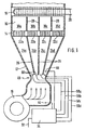
- the heater has a blower 10, the combustion air over feeds an air shaft 12 to a premix burner 14. about this is arranged a combustion chamber 16 through the top a heat exchanger 18 for in a line network 20 running water is complete.
- the premix burner 14 is divided into four burning zones 22, which the air over Individual channels 24a, b, c, d is supplied.
- the individual channels 24 are separated by partition walls 26 in the air shaft 12 separated.
- partition walls 28 Formation of chamber areas 30a, b, c, d provided with the individual channels 24 and the firing zones 22 correspond and are based on the height of the burnout path.
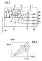
- the fuel gas is the heater via a main line 32 and a device 34 shown in more detail in Figure 2 for Controlling and regulating the performance of the premix burner 14 and of the gas / air ratio.
- the device 34 has two safety valves 36, 38 and connected downstream a gas pressure regulator 40 of known type, the control pressure is guided by a pneumatic composite actuator 42. This captures the air volume flow dependent Pressure difference between measuring points 44, 46, of which the one, 44, in the air shaft 12 in front of a constriction 48 and the other, 46, downstream of the constriction in the single channel 24d is arranged.
- the compound actuator 42 acts as known on a servo control valve 50 of the gas pressure regulator 40 and is with this and with the two safety valves 36, 38, as indicated in the drawing, to a gas-air composite fitting 52 structurally summarized.
- the output of the gas pressure regulator 40 is via a line 54 connected to a pressure chamber 56, from the individual lines 58a, b, c, d to in the individual channels 24 of the air shaft 12 arranged gas nozzles 60 lead.
- a Reference line 62 At one flow-reduced area of the pressure chamber 56 is a Reference line 62 connected, which the static Pressure ratios at the controller outlet in a control chamber of the Servo control valve 50 transmits.
- the individual lines 58 is an electromagnetically operated open / close valve 64 installed and each individual line 58 leads over a adjustable throttle device 66, its function below using the characteristic curve image according to FIG. 3 is explained.
- the difference between the pressures p 1 and p 2 which result as a function of the air flow delivered at the two measuring points 44, 46, is plotted on the abscissa of the characteristic curve image.
- the ordinate plots the difference between the regulated gas pressure p BR and the pressure p 2 at the measuring point 46, that is to say the excess pressure with which the gas reaches the respective individual channel 24 forming the mixing chamber.
- the operating behavior according to line a results when the gas flows unthrottled through the throttle device 66. By narrowing the through opening in the throttle device 66, the dashed lines b, c and d result, the distance e representing the possible range of the ratio setting.
- the pressure chamber 56, the on / off valves 64 and optionally the throttle devices 66 could also be used with the Gas / air composite fitting 52 structurally summarized or in these be integrated.
- the individual combustion zones 22 both the air and the gas are fed separately, whereby a good one in the individual channels 24 of the air shaft 12 Mixing of the two combustion components takes place.
- the individual channels 24 have the function of premixing chambers, the combustion zones 22 of the premix burner 14 individually assigned. While the firing zone 22d is permanently activated, the other firing zones 22a, b, c either individually or in groups via the on / off valves 64 can be switched on. It is also about the individual air channels not pressurized 24 conveyed air mixes with the exhaust gases downstream of the heat exchanger 18 and raises their dew point.
- the partitions 28 in the Combustion chamber 16 prevent mixed areas of air with a gas mixture that has not yet been completely burned.
- the power or Control range of the heater can be expanded because also in lower power range due to the air admixture Tendency to form condensate is largely avoided.
- a Extension of the control range is also facilitated or made possible because the detected between the measuring points 44, 46 Control pressure regardless of the number of activated Firing zones 22, i.e. decisive for all performance levels of the Premix burner 14 is.
- Switching individual on and off Firing zones 22 with unchanged air volume can the Do not change the amount of gas supplied to active combustion zones 22, because in the pressure chamber 56 only changes in the static Pressures are detected and regulated by the gas pressure regulator 40.
- the throttle devices 66 can be used for each one Firing zone 22 fine tunes the gas / air ratio made with changing air delivery of the blower 10 become.
Description
Die Erfindung geht aus von einem Gasheizgerät, insbesondere für Wassererhitzer, nach der Gattung des Hauptanspruchs. Bei bekannten Heizgeräten mit einem derart ausgebildeten Vormischbrenner (DE-A-44 46 945 und Patent Abstracts of Japan, vol. 008, ho. 022 (M-272), 31. Januar 1984 wird den Brennzonen die Luft über einen gemeinsamen Kanal und das Gas über je eine Einzelleitung zugeführt, wobei die Zumessung des Gases zu jeder Brennzone über je ein in der betreffenden Einzelleitung angeordnetes Regelventil erfolgt. Diese Anordnung ist verhältnismäßig aufwendig und wegen der nicht zwangsläufigen Zuteilung der Luft zu den einzelnen Brennzonen auch anfällig gegen Kondensatbildung in einem Wärmeübertrager und im Abgasweg.The invention is based on a gas heater, in particular for water heaters, according to the genus of the main claim. at known heaters with such a trained Premix burner (DE-A-44 46 945 and Patent Abstracts of Japan, vol. 008, ho. 022 (M-272), January 31 1984 the air becomes the burning zone via a common channel and the gas via one each Single line supplied, the metering of the gas to each firing zone over one in each Single line arranged control valve takes place. This Arrangement is relatively complex and not because of inevitable allocation of air to the individual Firing zones also prone to condensation in one Heat exchanger and in the exhaust gas path.
Die erfindungsgemäße Anordnung mit den kennzeichnenden Merkmalen des Hauptanspruchs hat demgegenüber den Vorteil, daß gesonderte Regelventile in den Gas-Einzelleitungen entfallen und infolge der gesteuerten Zufuhr von Luft zu den einzelnen Brennzonen die Neigung zur Kondensatbildung im Wärmeübertrager und im Abgasweg verringert ist. Die Luftzuführung zu den nicht aktivierten Brennzonen bleibt voll aufrechterhalten, wodurch der Taupunkt der Abgase erhöht und die Gefahr der Kondensatbildung weitgehend vermieden wird. Der vom geförderten Luftvolumenstrom abgeleitete Steuerdruck für den Gas/Luft-Verbundregler und damit dessen einwandfreie Funktion, bleiben auch im Teillastbereich des Vormischbrenners voll erhalten.The arrangement according to the invention with the characteristic In contrast, features of the main claim have the advantage that separate control valves in the gas individual lines omitted and due to the controlled supply of air to the individual burning zones the tendency to form condensate in the Heat exchanger and in the exhaust gas path is reduced. The Air supply to the non-activated burning zones remains fully maintained, creating the dew point of the exhaust gases increased and the risk of condensation largely is avoided. The air volume flow conveyed derived control pressure for the gas / air compound controller and thus its flawless function remain in the Partial load range of the premix burner fully preserved.
Durch die in den Unteransprüchen aufgeführten Merkmale sind vorteilhafte Ausgestaltungen der Anordnung nach dem Hauptanspruch möglich.By the features listed in the subclaims advantageous embodiments of the arrangement according to Main claim possible.
Zur Vermeidung von Mischbereichen von Luft und noch nicht vollständig verbranntem Gas/Luftgemisch wird vorgeschlagen, daß auch in der Brennkammer Einzelkanäle gebildet sind, die mit den Einzelkanälen im Luftschacht, bzw. mit den Brennzonen korrespondieren und deren Höhe sich an der Ausbrandstrecke orientiert.To avoid mixing areas of air and not yet completely burned gas / air mixture is suggested that individual channels are also formed in the combustion chamber with the individual channels in the air shaft, or with the Firing zones correspond and their height varies with the Burnout path oriented.
Um die Abhängigkeit des Gasregeldrucks vom Gasvolumenstrom zu minimieren, bzw. auszuschalten, wird weiter vorgeschlagen, daß die Gas-Einzelleitungen in einer mit dem Ausgang des Gas/Luft-Verbundreglers verbundenen Druckkammer beginnen und eine den Ausgangsdruck an ein Steuerglied des Reglers leitende Referenzleitung aus einem strömungsberuhigten Bereich der Druckkammer herausführt. Dadurch ist erreicht, daß nur Änderungen der statischen Druckverhältnisse ausgangsseitig des Gas/Luft-Verbundreglers erfaßt und ausgeregelt werden. Die Druckkammer kann in den Regler integriert oder als eigenständiges Bauteil ausgebildet sein.The dependence of the gas control pressure on the gas volume flow to minimize or to switch off will continue proposed that the gas individual lines in one with the Output of the gas / air compound regulator connected pressure chamber begin and the output pressure to a control element of the Controller leading reference line from one leads flow-free area of the pressure chamber. This ensures that only changes to the static Pressure conditions on the outlet side of the gas / air compound controller be recorded and corrected. The pressure chamber can in the Integrated controller or as an independent component be trained.
In den Gas-Einzelleitungen ist eine Drosseleinrichtung zur Einstellung der Steigung der Gas/Luft-Kennlinie angeordnet. A throttle device is provided in the individual gas lines Adjustment of the slope of the gas / air characteristic curve arranged.
Dadurch kann der Gas/Luft-Verbundregler in vorteilhafter Weise an das entsprechende System angepaßt werden. Darüberhinaus kann das Gasheizgerät mit unterschiedlichen Gasarten betrieben werden.As a result, the gas / air composite controller can be advantageous Be adapted to the corresponding system. In addition, the gas heater can be used with different Gas types are operated.
Ein Ausführungsbeispiel der Erfindung ist schematisch in der
Zeichnung dargestellt und in der nachfolgenden Beschreibung
erläutert. Es zeigen
Das Heizgerät hat ein Gebläse 10, das Verbrennungsluft über
einen Luftschacht 12 einem Vormischbrenner 14 zuführt. Über
diesem ist eine Brennkammer 16 angeordnet, die oben durch
einen Wärmeübertrager 18 für in einem Leitungsnetz 20
fließendes Wasser abgeschlossen ist. Der Vormischbrenner 14
ist in vier Brennzonen 22 geteilt, denen die Luft über
Einzelkanäle 24a, b, c, d zugeführt ist. Die Einzelkanäle 24
sind durch Zwischenwände 26 im Luftschacht 12 voneinander
abgeteilt. In der Brennkammer 16 sind Zwischenwände 28 zur
Bildung von Kammerbereichen 30a, b, c, d vorgesehen, die mit
den Einzelkanälen 24 und den Brennzonen 22 korrespondieren
und sich an der Höhe der Ausbrandstrecke orientieren.The heater has a
Das Brenngas ist dem Heizgerät über eine Hauptleitung 32 und
eine in Figur 2 näher dargestellte Einrichtung 34 zum
Steuern und Regeln der Leistung des Vormischbrenners 14 und
des Gas/Luft-Verhältnisses zugeführt. Die Einrichtung 34 hat
zwei Sicherheitsventile 36, 38 und diesen nachgeschaltet
einen Gasdruckregler 40 bekannter Bauart, dessen Regeldruck
von einem pneumatischen Verbundstellglied 42 geführt ist.
Dieses erfaßt die vom geförderten Luftvolumenstrom abhängige
Druckdifferenz zwischen Meßpunkten 44, 46, von denen der
eine, 44, im Luftschacht 12 vor einer Einschnürung 48 und
der andere, 46, stromab der Einschnürung im Einzelkanal 24d
angeordnet ist. Das Verbundstellglied 42 wirkt wie bekannt
auf ein Servo-Steuerventil 50 des Gasdruckreglers 40 ein und
ist mit diesem sowie mit den beiden Sicherheitsventilen 36,
38, wie in der Zeichnung angedeutet, zu einer Gas-Luft-Verbundarmatur
52 baulich zusammengefaßt.The fuel gas is the heater via a
Der Ausgang des Gasdruckreglers 40 ist über eine Leitung 54
mit einer Druckkammer 56 verbunden, aus der Einzelleitungen
58a, b, c, d zu in den Einzelkanälen 24 des Luftschachts 12
angeordneten Gasdüsen 60 führen. An einen
strömungsberuhigten Bereich der Druckkammer 56 ist eine
Referenzleitung 62 angeschlossen, welche die statischen
Druckverhältnisse am Reglerausgang in eine Steuerkammer des
Servo-Steuerventils 50 überträgt. In den Einzelleitungen 58
ist je ein elektromagnetisch betätigtes Auf/Zu-Ventil 64
eingebaut und jede Einzelleitung 58 führt über eine
verstellbare Drosseleinrichtung 66, deren Funktion
nachstehend anhand des Kennlinienbildes nach Figur 3
erläutert ist.The output of the
Auf der Abszisse des Kennlinienbildes ist die Differenz der
Drücke p1 und p2 aufgetragen, die sich abhängig vom
geförderten Luftstrom an den beiden Meßpunkten 44, 46
ergeben. Auf der Ordinate ist die Differenz zwischen dem
geregelten Gasdruck pBR und dem Druck p2 am Meßpunkt 46
aufgetragen, also der Drucküberschuß, mit welchem das Gas in
den betreffenden, die Mischkammer bildenden Einzelkanal 24
gelangt. Das Betriebsverhalten gemäß Linie a ergibt sich,
wenn das Gas ungedrosselt durch die Drosseleinrichtung 66
strömt. Durch Verengen der Durchgangsöffnung in der
Drosseleinrichtung 66 ergeben sich die gestrichelt
gezeichneten Kennlinien b, c und d, wobei die Strecke e den
möglichen Bereich der Verhältniseinstellung darstellt.The difference between the pressures p 1 and p 2 , which result as a function of the air flow delivered at the two
Die Druckkammer 56, die Auf/Zu-Ventile 64 und gegebenenfalls
auch die Drosseleinrichtungen 66 könnten auch mit der
Gas/Luft-Verbundarmatur 52 baulich zusammengefaßt bzw. in
diese integriert sein.The
Im Betrieb des Heizgerätes wird den einzelnen Brennzonen 22
sowohl die Luft als auch das Gas getrennt zugeführt, wobei
in den Einzelkanälen 24 des Luftschachts 12 eine gute
Durchmischung der beiden Verbrennungskomponenten erfolgt.
Die Einzelkanäle 24 haben die Funktion von Vormischkammern,
die den Brennzonen 22 des Vormischbrenners 14 einzeln
zugeordnet sind. Während im Betrieb die Brennzone 22d
ständig aktiviert ist, können die übrigen Brennzonen 22a, b,
c wahlweise einzeln oder gruppenweise über die Auf/Zu-Ventile
64 zugeschaltet werden. Dabei wird auch über die
nicht gasbeaufschlagten Einzelkanäle 24 Luft gefördert, die
sich stromab des Wärmeübertragers 18 mit den Abgasen mischt
und deren Taupunkt anhebt. Die Zwischenwände 28 in der
Brennkammer 16 verhindern, daß sich Mischbereiche von Luft
mit noch nicht vollständig verbranntem Gasgemisch ergeben.During operation of the heater, the individual combustion zones 22
both the air and the gas are fed separately, whereby
a good one in the individual channels 24 of the
Durch die beschriebene Anordnung kann der Leistungs- bzw.
Regelbereich des Heizgerätes erweitert werden, weil auch im
unteren Leistungsbereich durch die Luftzumischung die
Neigung zur Kondensatbildung weitgehend vermieden ist. Eine
Erweiterung des Regelbereichs wird auch erleichtert bzw.
ermöglicht, weil der zwischen den Meßpunkten 44, 46 erfaßte
Steuerdruck unabhängig von der Anzahl der aktivierten
Brennzonen 22, d.h. maßgebend für alle Leistungsstufen des
Vormischbrenners 14 ist. Ein Zu- und Abschalten einzelner
Brennzonen 22 bei unveränderter Luftmenge kann die den
aktiven Brennzonen 22 zugeführte Gasmenge nicht verändern,
weil in der Druckkammer 56 nur Änderungen der statischen
Drücke erfaßt und vom Gasdruckregler 40 ausgeregelt werden.
Mit den Drosseleinrichtungen 66 kann für jede einzelne
Brennzone 22 eine Feinabstimmung des Gas/Luftverhältnisses
bei sich ändernder Luftförderung des Gebläses 10 vorgenommen
werden.With the arrangement described, the power or
Control range of the heater can be expanded because also in
lower power range due to the air admixture
Tendency to form condensate is largely avoided. A
Extension of the control range is also facilitated or
made possible because the detected between the
Claims (4)
- Gas-operated heating appliance, in particular for water heaters, with a premixing burner which is divided, for the purpose of power grading, into individually activatable combustion zones, to which the combustion air is supplied jointly, regulated by means of a blower and the fuel gas, in each case via an individual line, characterized by the following features:a) the combustion air is supplied, like the fuel gas, to each combustion zone (22a, b, c, d) via an individual duct (24a, b, c, d),b) a composite gas/air controller (52) controlled by the air volume flow is installed in a main line (32) feeding all the individual fuel-gas lines (58a, b, c, d),c) on/off valves (64) are provided in the respective individual fuel-gas lines (58a, b, c, d) for switching on and off the gas supply to individual combustion zones (22a, b, c, d), the air supply to the non-activated combustion zones being fully maintained.
- Heating appliance according to Claim 1, characterized in that the combustion chamber (16), too, has formed in it individual ducts (30a, b, c, d) which match with the individual ducts (24a, b, c, d) in the air well (12) or with the combustion zones (22a, b, c, d) and the height of which is governed by the burn-up distance.
- Heating appliance according to Claim 1 or 2, characterized in that the individual fuel-gas lines (58a, b, c, d) commence in a pressure chamber (56) connected to the output of the composite gas/air controller (52), and a reference line (62) conducting the outlet pressure to a control member (50) of the controller leads out of a flow-stabilized region of the pressure chamber (56).
- Heating appliance according to one of the preceding claims, characterized in that a throttle device (66) for setting the gradient of the gas/air characteristic curve is arranged in each individual fuel/gas line (58a, b, c, d).
Applications Claiming Priority (2)
| Application Number | Priority Date | Filing Date | Title |
|---|---|---|---|
| DE19711151 | 1997-03-18 | ||
| DE19711151A DE19711151A1 (en) | 1997-03-18 | 1997-03-18 | Gas heater, especially for water heaters |
Publications (3)
| Publication Number | Publication Date |
|---|---|
| EP0866270A2 EP0866270A2 (en) | 1998-09-23 |
| EP0866270A3 EP0866270A3 (en) | 1999-08-18 |
| EP0866270B1 true EP0866270B1 (en) | 2003-05-28 |
Family
ID=7823716
Family Applications (1)
| Application Number | Title | Priority Date | Filing Date |
|---|---|---|---|
| EP97121200A Expired - Lifetime EP0866270B1 (en) | 1997-03-18 | 1997-12-03 | Gas-fired heating apparatus, especially a water heater |
Country Status (2)
| Country | Link |
|---|---|
| EP (1) | EP0866270B1 (en) |
| DE (2) | DE19711151A1 (en) |
Families Citing this family (4)
| Publication number | Priority date | Publication date | Assignee | Title |
|---|---|---|---|---|
| US6312250B1 (en) | 1999-04-19 | 2001-11-06 | North American Manufacturing Company | Premix burner with firing rate control |
| DE69929769T2 (en) * | 1999-09-09 | 2006-11-02 | Scanferla, Giorgio, Bassano del Grappa | Burner assembly and burner head for gas mixture combustion |
| ATE445126T1 (en) | 2001-05-18 | 2009-10-15 | Bekaert Comb Technology Bv | NON-CONDENSING GAS BURNER WITH PREMIXTION |
| US7494337B2 (en) * | 2004-04-22 | 2009-02-24 | Thomas & Betts International, Inc. | Apparatus and method for providing multiple stages of fuel |
Family Cites Families (5)
| Publication number | Priority date | Publication date | Assignee | Title |
|---|---|---|---|---|
| DE910585C (en) * | 1951-08-01 | 1954-05-03 | Richard Huelzer | Gas-heated liquid water heater |
| JPS58182031A (en) * | 1982-04-16 | 1983-10-24 | Matsushita Electric Ind Co Ltd | Combustion control device |
| JP3060730B2 (en) * | 1992-06-30 | 2000-07-10 | 株式会社ノーリツ | Combustion equipment |
| DE4446945B4 (en) | 1994-12-28 | 2005-03-17 | Alstom | Gas powered premix burner |
| JPH09264526A (en) * | 1996-03-26 | 1997-10-07 | Tokyo Gas Co Ltd | Alternating combustion system |
-
1997
- 1997-03-18 DE DE19711151A patent/DE19711151A1/en not_active Withdrawn
- 1997-12-03 EP EP97121200A patent/EP0866270B1/en not_active Expired - Lifetime
- 1997-12-03 DE DE59710173T patent/DE59710173D1/en not_active Expired - Fee Related
Also Published As
| Publication number | Publication date |
|---|---|
| EP0866270A3 (en) | 1999-08-18 |
| EP0866270A2 (en) | 1998-09-23 |
| DE19711151A1 (en) | 1998-09-24 |
| DE59710173D1 (en) | 2003-07-03 |
Similar Documents
| Publication | Publication Date | Title |
|---|---|---|
| EP0644377B1 (en) | Control device for gas burners | |
| DE2914681C2 (en) | Control device for a burner | |
| DE2832708C2 (en) | ||
| EP0356690B1 (en) | Fuel-fired heat producer | |
| EP0062854B1 (en) | Gas-fired water or air heater | |
| EP0907052A2 (en) | Pneumatic ratio controller | |
| EP0505714B1 (en) | Control device for a gas burner with a fan for supplying combustion air | |
| EP2071156B1 (en) | Fuel distribution system for a gas turbine with multistage burner arrangement | |
| EP0866270B1 (en) | Gas-fired heating apparatus, especially a water heater | |
| DE2906223A1 (en) | FUEL CONTROL FOR TURBINE AFTERBURNER | |
| DE19822336C2 (en) | Device for operating an atmospheric, in particular fully premixed gas burner | |
| DE3927416C2 (en) | Gas central heating burner | |
| DE2752663A1 (en) | Gas burner automatic air-fuel ratio regulating equipment - has thermostatic unit controlling gas valve, linked airflow control flap | |
| EP1028287A1 (en) | Atmospheric gas burner and gas distribution manifold for a gas burner | |
| DE102011002324A1 (en) | Regulating device for premix burner, has throttle element arranged downstream to throttle device in fuel supply spacer, and mixer arranged downstream from fan to air supply pipe and downstream from throttle element to fuel supply spacer | |
| DE3826279C2 (en) | Gas burner with a burner chamber | |
| AT393888B (en) | PRE-MIXED GAS BURNER | |
| DE19810750A1 (en) | Method and device for operating an atmospheric gas burner | |
| AT395764B (en) | Premixing gas burner | |
| EP0916895B1 (en) | Method for controlling an atmospheric gas burner for heaters, especially for water heaters | |
| EP0908670B1 (en) | Device for operating an atmospheric gas burner | |
| DE19503781A1 (en) | Gas or oil burner air flow mixing system | |
| EP0036613A1 (en) | Regulation apparatus for a gas-fired water or air heater which is controllable by a temperature sensor | |
| EP0108349A2 (en) | Gas-fired heat source | |
| EP0733857B1 (en) | Control device for a burner with a chamber for the combustion air |
Legal Events
| Date | Code | Title | Description |
|---|---|---|---|
| PUAI | Public reference made under article 153(3) epc to a published international application that has entered the european phase |
Free format text: ORIGINAL CODE: 0009012 |
|
| AK | Designated contracting states |
Kind code of ref document: A2 Designated state(s): DE FR GB IT NL |
|
| AX | Request for extension of the european patent |
Free format text: AL;LT;LV;MK;RO;SI |
|
| PUAL | Search report despatched |
Free format text: ORIGINAL CODE: 0009013 |
|
| AK | Designated contracting states |
Kind code of ref document: A3 Designated state(s): AT BE CH DE DK ES FI FR GB GR IE IT LI LU MC NL PT SE |
|
| AX | Request for extension of the european patent |
Free format text: AL;LT;LV;MK;RO;SI |
|
| 17P | Request for examination filed |
Effective date: 20000218 |
|
| AKX | Designation fees paid |
Free format text: DE FR GB IT NL |
|
| GRAH | Despatch of communication of intention to grant a patent |
Free format text: ORIGINAL CODE: EPIDOS IGRA |
|
| GRAH | Despatch of communication of intention to grant a patent |
Free format text: ORIGINAL CODE: EPIDOS IGRA |
|
| GRAA | (expected) grant |
Free format text: ORIGINAL CODE: 0009210 |
|
| AK | Designated contracting states |
Designated state(s): DE FR GB IT NL |
|
| PG25 | Lapsed in a contracting state [announced via postgrant information from national office to epo] |
Ref country code: NL Free format text: LAPSE BECAUSE OF FAILURE TO SUBMIT A TRANSLATION OF THE DESCRIPTION OR TO PAY THE FEE WITHIN THE PRESCRIBED TIME-LIMIT Effective date: 20030528 Ref country code: IT Free format text: LAPSE BECAUSE OF FAILURE TO SUBMIT A TRANSLATION OF THE DESCRIPTION OR TO PAY THE FEE WITHIN THE PRE;WARNING: LAPSES OF ITALIAN PATENTS WITH EFFECTIVE DATE BEFORE 2007 MAY HAVE OCCURRED AT ANY TIME BEFORE 2007. THE CORRECT EFFECTIVE DATE MAY BE DIFFERENT FROM THE ONE RECORDED.SCRIBED TIME-LIMIT Effective date: 20030528 Ref country code: GB Free format text: LAPSE BECAUSE OF FAILURE TO SUBMIT A TRANSLATION OF THE DESCRIPTION OR TO PAY THE FEE WITHIN THE PRESCRIBED TIME-LIMIT Effective date: 20030528 Ref country code: FR Free format text: LAPSE BECAUSE OF FAILURE TO SUBMIT A TRANSLATION OF THE DESCRIPTION OR TO PAY THE FEE WITHIN THE PRESCRIBED TIME-LIMIT Effective date: 20030528 |
|
| REG | Reference to a national code |
Ref country code: GB Ref legal event code: FG4D Free format text: NOT ENGLISH |
|
| REF | Corresponds to: |
Ref document number: 59710173 Country of ref document: DE Date of ref document: 20030703 Kind code of ref document: P |
|
| NLV1 | Nl: lapsed or annulled due to failure to fulfill the requirements of art. 29p and 29m of the patents act | ||
| GBV | Gb: ep patent (uk) treated as always having been void in accordance with gb section 77(7)/1977 [no translation filed] |
Effective date: 20030528 |
|
| PLBE | No opposition filed within time limit |
Free format text: ORIGINAL CODE: 0009261 |
|
| STAA | Information on the status of an ep patent application or granted ep patent |
Free format text: STATUS: NO OPPOSITION FILED WITHIN TIME LIMIT |
|
| 26N | No opposition filed |
Effective date: 20040302 |
|
| EN | Fr: translation not filed | ||
| PGFP | Annual fee paid to national office [announced via postgrant information from national office to epo] |
Ref country code: DE Payment date: 20050208 Year of fee payment: 8 |
|
| PG25 | Lapsed in a contracting state [announced via postgrant information from national office to epo] |
Ref country code: DE Free format text: LAPSE BECAUSE OF NON-PAYMENT OF DUE FEES Effective date: 20060701 |