EP1062402B1 - Dispositif de commande de leve-vitre par cable - Google Patents
Dispositif de commande de leve-vitre par cable Download PDFInfo
- Publication number
- EP1062402B1 EP1062402B1 EP99924662A EP99924662A EP1062402B1 EP 1062402 B1 EP1062402 B1 EP 1062402B1 EP 99924662 A EP99924662 A EP 99924662A EP 99924662 A EP99924662 A EP 99924662A EP 1062402 B1 EP1062402 B1 EP 1062402B1
- Authority
- EP
- European Patent Office
- Prior art keywords
- cable
- drive mechanism
- lift drive
- window lift
- mechanism according
- Prior art date
- Legal status (The legal status is an assumption and is not a legal conclusion. Google has not performed a legal analysis and makes no representation as to the accuracy of the status listed.)
- Expired - Lifetime
Links
Images


Classifications
-
- E—FIXED CONSTRUCTIONS
- E05—LOCKS; KEYS; WINDOW OR DOOR FITTINGS; SAFES
- E05F—DEVICES FOR MOVING WINGS INTO OPEN OR CLOSED POSITION; CHECKS FOR WINGS; WING FITTINGS NOT OTHERWISE PROVIDED FOR, CONCERNED WITH THE FUNCTIONING OF THE WING
- E05F11/00—Man-operated mechanisms for operating wings, including those which also operate the fastening
- E05F11/38—Man-operated mechanisms for operating wings, including those which also operate the fastening for sliding windows, e.g. vehicle windows, to be opened or closed by vertical movement
- E05F11/48—Man-operated mechanisms for operating wings, including those which also operate the fastening for sliding windows, e.g. vehicle windows, to be opened or closed by vertical movement operated by cords or chains or other flexible elongated pulling elements, e.g. tapes
- E05F11/481—Man-operated mechanisms for operating wings, including those which also operate the fastening for sliding windows, e.g. vehicle windows, to be opened or closed by vertical movement operated by cords or chains or other flexible elongated pulling elements, e.g. tapes for vehicle windows
- E05F11/483—Man-operated mechanisms for operating wings, including those which also operate the fastening for sliding windows, e.g. vehicle windows, to be opened or closed by vertical movement operated by cords or chains or other flexible elongated pulling elements, e.g. tapes for vehicle windows by cables
-
- E—FIXED CONSTRUCTIONS
- E05—LOCKS; KEYS; WINDOW OR DOOR FITTINGS; SAFES
- E05F—DEVICES FOR MOVING WINGS INTO OPEN OR CLOSED POSITION; CHECKS FOR WINGS; WING FITTINGS NOT OTHERWISE PROVIDED FOR, CONCERNED WITH THE FUNCTIONING OF THE WING
- E05F15/00—Power-operated mechanisms for wings
- E05F15/60—Power-operated mechanisms for wings using electrical actuators
- E05F15/603—Power-operated mechanisms for wings using electrical actuators using rotary electromotors
- E05F15/665—Power-operated mechanisms for wings using electrical actuators using rotary electromotors for vertically-sliding wings
- E05F15/689—Power-operated mechanisms for wings using electrical actuators using rotary electromotors for vertically-sliding wings specially adapted for vehicle windows
- E05F15/697—Motor units therefor, e.g. geared motors
-
- E—FIXED CONSTRUCTIONS
- E05—LOCKS; KEYS; WINDOW OR DOOR FITTINGS; SAFES
- E05Y—INDEXING SCHEME RELATING TO HINGES OR OTHER SUSPENSION DEVICES FOR DOORS, WINDOWS OR WINGS AND DEVICES FOR MOVING WINGS INTO OPEN OR CLOSED POSITION, CHECKS FOR WINGS AND WING FITTINGS NOT OTHERWISE PROVIDED FOR, CONCERNED WITH THE FUNCTIONING OF THE WING
- E05Y2201/00—Constructional elements; Accessories therefore
- E05Y2201/60—Suspension or transmission members; Accessories therefore
- E05Y2201/622—Suspension or transmission members elements
- E05Y2201/71—Toothed gearing
- E05Y2201/726—Ring gears; Internal gears
-
- E—FIXED CONSTRUCTIONS
- E05—LOCKS; KEYS; WINDOW OR DOOR FITTINGS; SAFES
- E05Y—INDEXING SCHEME RELATING TO HINGES OR OTHER SUSPENSION DEVICES FOR DOORS, WINDOWS OR WINGS AND DEVICES FOR MOVING WINGS INTO OPEN OR CLOSED POSITION, CHECKS FOR WINGS AND WING FITTINGS NOT OTHERWISE PROVIDED FOR, CONCERNED WITH THE FUNCTIONING OF THE WING
- E05Y2800/00—Details, accessories and auxiliary operations not otherwise provided for
- E05Y2800/10—Additional functions
- E05Y2800/12—Sealing
-
- E—FIXED CONSTRUCTIONS
- E05—LOCKS; KEYS; WINDOW OR DOOR FITTINGS; SAFES
- E05Y—INDEXING SCHEME RELATING TO HINGES OR OTHER SUSPENSION DEVICES FOR DOORS, WINDOWS OR WINGS AND DEVICES FOR MOVING WINGS INTO OPEN OR CLOSED POSITION, CHECKS FOR WINGS AND WING FITTINGS NOT OTHERWISE PROVIDED FOR, CONCERNED WITH THE FUNCTIONING OF THE WING
- E05Y2900/00—Application of doors, windows, wings or fittings thereof
- E05Y2900/50—Application of doors, windows, wings or fittings thereof for vehicles
- E05Y2900/53—Application of doors, windows, wings or fittings thereof for vehicles characterised by the type of wing
- E05Y2900/55—Windows
Definitions
- the invention relates to a cable window drive with central fastening and sealing in the carrier plate the preamble of claim 1.
- Rope window lifter for one in a window shaft Vehicle retractable window have a moving direction the guide rail arranged on, along one that attacks on the lower edge of the pane and with a sliding cable connected to a drive cable of the cable window lifter is arranged displaceably in the longitudinal direction.
- the Drive cable is led to a drive unit, the one Drive housing with a cable drum arranged in it for receiving the drive cable and one in an internal toothing the rope drum has engaging drivers, which is connected to a hand crank or a motor drive can be.
- the drive cable is usually arranged in a Bowden sheath, which is attached to Bowden supports of the drive housing is.
- the drive cable itself closes on the cylindrical one Surface of the rope drum and is with the rope drum so connected that when the driver is actuated in one way or the other direction of rotation of the drive cable the cable drum is wound up and unwound, so that with connected to the disc and guided on the guide rail Carrier is moved up and down.
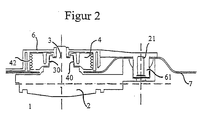
- FIG. 1 shows the documentation of the prior art an exploded view of a cable window drive with a cable drum and a bearing cap and Figure 2 a section through a cable window drive, the a mounting plate of a motor vehicle door is mounted.
- the drive unit 1 consists of an electric motor 11, a transmission 12 and an electronics module 13, which in a drive housing 2 are mounted.
- the drive unit 1 has a multi-tooth driver 3 on, the outer toothing 30 in the inner toothing 40th a cable drum 4 engages in a cylindrical Recess 60 of a bearing cover 6 is arranged.
- the multi-tooth driver 3 has an external toothing 30 and on its end face facing away from the external toothing 30 three driver pins 31 on the for power transmission necessary positive locking with a not shown,
- Driver gear element mounted in the axis of the cable drum ensure that from one with the Axis of the electric motor 11 connected drive worm Gear 12 is driven.
- the bearing cover 6 has two cable guide channels 64, 65, which open into openings 66, 67, where that in a spiral Groove 42 of the cable drum 4 inserted and around the cable drum 4 wound window lifter rope emerges and at the ends the window regulator rails with the drivers of the window pane connected is.
- FIG. 2 shows the assembled Condition of the cable window drive, in which the fasteners 21, 22, 23 and 61, 62, 63 through an opening a support plate 7 inserted and with screws together are connected.
- the section shown in Figure 2 through a cable window drive illustrates that the drive unit during assembly 1 first on the plugged through the carrier plate 7 Fasteners (domes) 61 (and not shown 62 and 63) when plugging the drive housing 2 onto the Bearing cover 6 is centered before the driver teeth 30 engages in the cable drum toothing 40. Subsequently the bearing cap 6 is attached and the Connection of the drive unit 1 to the bearing cover 6 or the carrier plate 7 is for example via a snap connection or by tightening the fastening screws.
- DE 43 19 705 C2 describes a device for Attachment of a window motor known by means of fastening positions arranged on the circumference of the motor housing the motor is attached to the inner door panel.
- a firm connection between the motor housing and the To enable the door inner panel are between the protuberances of the motor housing and the inner door panel spacer sleeves intended.
- WO 98/38057 is a motor-gear unit for adjusting devices in motor vehicles known in a Opening a separating a wet room from a dry room Wall is mounted on a base plate.
- the output of the The drive is located on the wet room side and Elements for electrical contacting are on the drying room side arranged.
- one is the opening of the Sealing area surrounding the wall is provided, the is arranged between the wall and the base plate.
- the base plate forms with at least part of the Gearbox housing one unit and is from the wet room side mounted on the wall.
- the object of the invention is a cable window drive To provide a simplified assembly with a few Components enabled and a small footprint at the same time low tolerance requirements regarding the Manufacturing accuracy required.
- the cable window lifter drive according to the invention requires the carrier sheet much less space than conventional Drives because of the design of the domes in the bearing caps outside the gear element or the cable drum can be dispensed with. There are still three Screwing operations and three sets of fastening or Screw fasteners so that an additional material and assembly time saving is achieved.
- Another advantage of the cable window lifter drive according to the invention consists in the lower tolerance requirements in terms of production, since only one hole or a recess is to be provided and thus dependent dimensions, as in the conventional design through the holes and domes are eliminated.
- the motor axis is in integrated the bearing cover on the wet room side, creating a Ease of assembly is effected.
- the wet room side Bearing cover together with the motor axis is on the carrier plate pre-assembled, depending on the design of the rope drum and the gear element one or both components already are attached to the motor axis.
- the drying room side The bearing cover is then pushed onto the axle and fixed on the axis via the fasteners.
- a first centering of the gear element or the cable drum takes place here via the seal on the carrier plate is appropriate. So with just one screw or Fixing device of the cable window drive be mounted on the carrier plate.
- This type of attachment is also used for service operations, very cheap, because only the inner lining of the door must be removed to get to the corresponding component reach. Most services can therefore be on the drying room side be done, what a saving at Assembly and repair time.
- an advantageous further development consists in an anti-rotation device the bearing cover, which is preferably designed to be form-fitting is.
- a molded projection of the bearing cover who takes part in one or more surveys of the Backing sheet supports is made simple and effective How to prevent the bearing cap from rotating, for example when the window pane moves against a stop becomes. Furthermore, they are reduced by the anti-rotation device the clamping forces to be applied since there is no anti-twist device a turn with a frictional connection between the carrier plate and the bearing cover with the corresponding high clamping forces would have to be prevented.
- the seal can be integrally formed on the carrier plate, in corresponding Recordings of the carrier plate inserted or on another Art to be mounted on the carrier plate.
- the shape of the radial seal lends itself because both the gear element and the cable drum preferably has round cross sections, so that one or more radial seals are more efficient Protection against moisture penetration guaranteed can be.
- the radial seals can be made from known commercially available radial shaft seals or from the Carrier sheet molded plastic or rubber lips exist.
- the radial seal is housed in one of the two bearing caps, see above that the seal is made at the most favorable point can.
- the seal is arranged on the wet room side becomes a clamping effect due to the elastic forces of the seal exerted on the cable drum or the gear element, which facilitates assembly, since the corresponding component is pre-fixed.
- Persist Manufacturing advantages as a bearing cover is lighter is manageable as a carrier plate and thus the seal can be easily mounted in a bearing cap. As Variant are radial seals in both bearing caps intended.
- Gear element and the cable drum advantageously in one piece educated. Due to the one-piece embodiment can on a torque transmitting connection, for example the multi-tooth driver, between the gear element and Rope drum can be dispensed with. It just becomes a component pushed onto the motor axis so that alignment of The cable drum and gear element are not required during assembly.
- a torque transmitting connection for example the multi-tooth driver
- the bearing cover For simple and reversible attachment of the bearing cover on the carrier plate and a corresponding orientation to each other, there is a screw thread on the motor axis the bearing cover is provided.
- FIG. 3 shows one cable window lifter drive attached to a carrier plate 7, which has an electric motor 11 which has a screw 16 and a worm wheel 17 drives a gear element 5.
- the gear element 5 a rope drum 4 formed in one piece, so that via the gear element 5 directly the rope drum 4 is driven.
- Conceivable and provided as a variant is also that the gear element 5 via a toothing, for example a multiple toothing with which separately manufactured rope drum 4 is connected, or that an intermediate piece like the multi-tooth element 3 the force transfers.
- the gear element 5 and the cable drum 4 are on one Motor axis 9 mounted, which is integrated in the bearing cap 6b is, of course, the bearing cap 6a Motor axis 9 can accommodate.
- the motor axis 9 can by a molding process, e.g. Injecting through primary or forming processes or by a joining process, for example Welding, with one of the bearing caps 6a, 6b permanently in Be connected. Pressing in is also conceivable or screw in, as far as the accuracy requirements can be fulfilled.
- the motor axis 9 projects according to FIG. 3 in a preassembly position through an opening 18 in the carrier plate 7 through to the drying room side.
- the cable drum 4 and the gear element 5 the motor axis 9 pushed on and by a on the carrier plate 7 attached seal 10 held in this position.
- the surface of the gear element 5 or the cable drum 4 is at the point where the seal 10 is applied accordingly, so that no excessive Wear occurs.
- rope drum 4 and gear element 5 is from the drying room side pushed out of the bearing cover 6a onto the motor axis 9 and then by a fastener 8, here as Mother executed, fixed.
- the worm 16 with the motor 11 can already be attached to the bearing cover 6a be or only after the assembly of the bearing cover 6a, 6b can be mounted.
- the bearing cover 6a on the dry room side has an anti-rotation device 14, which is in the form of a shape of the carrier plate 7 and a corresponding receptacle 14.
- the bearing cover 6a is secured to it by the anti-rotation device 14 prevented from adjusting due to the reaction forces to rotate on the carrier plate 7 about the motor axis 9. This allows the clamping forces to be applied via the fasteners 8 must be applied, reduced accordingly be, since only a firm concern of the bearing cover 6a, 6b on the carrier plate 7 must be ensured.
- the anti-rotation device 14 can also on the Bearing cover 6b may be attached or in multiple designs available.
- the design of the anti-rotation 14 many variants are possible, the form-fitting Definitions of the bearing caps 6a, 6b advantageous in terms of manufacturing costs, ease of assembly as well as the variety of designs.
- the Sealing 10 from dry to wet room in one of the bearing caps 6a, 6b attached.
- the contact surface of the seal 10, which is preferably designed as a radial seal is accordingly outside the level of Carrier plates 7 on one side of the bearing caps 6a, 6b.
- gear element 5 and cable drum 4 which over a torque-transmitting element in connection with each other be set.
- This element can, for example, consist of an intermediate multi-tooth driver 3 or one molded teeth on the cable drum 4 and the gear element 5 exist. This also gives the opportunity both the cable drum 4 and the gear element 5 separately in the respective bearing caps 6a, 6b. Optionally, only one seal should be provided.
Claims (9)
- Dispositif de commande par câble pour lève-vitre, destiné à être fixé sur une tôle porteuse, comportant un arbre moteur pour recevoir un tambour à câble et un élément de transmission, ainsi que deux couvercles de montage qui sont agencés des deux côtés sur la tôle porteuse, caractérisé en ce que l'arbre moteur est intégré dans l'un des couvercles de montage (6a, 6b), en ce que les couvercles de montage (6a, 6b) peuvent être fixés dans leur position l'un par rapport à l'autre sur la tôle porteuse (7) via des moyens de fixation (8) sur l'arbre moteur (9), et en ce qu'un étanchement (10) s'effectue à la périphérie du tambour à câble (4) et/ou de l'élément de transmission (5).
- Dispositif de commande par câble pour lève-vitre selon la revendication 1, caractérisé en ce que l'arbre moteur (9) est intégré dans le couvercle de montage (6b) côté espace humide.
- Dispositif de commande par câble pour lève-vitre selon l'une ou l'autre des revendications 1 et 2, caractérisé par un blocage anti-rotation (14).
- Dispositif de commande par câble pour lève-vitre selon la revendication 3, caractérisé par un blocage anti-rotation (14) par coopération de formes.
- Dispositif de commande par câble pour lève-vitre selon l'une au moins des revendications précédentes, caractérisé par un joint d'étanchement radial (10) entre l'espace sec et l'espace humide sur la tôle porteuse (7).
- Dispositif de commande par câble pour lève-vitre selon la revendication 5, caractérisé en ce que le joint d'étanchement radial (10) est conformé sur la tôle porteuse (7).
- Dispositif de commande par câble pour lève-vitre selon l'une au moins des revendications 1 à 4, caractérisé en ce que l'étanchement (10) sous forme de joint radial (10) est fixé dans l'un des couvercles de montage (6a, 6b).
- Dispositif de commande par câble pour lève-vitre selon l'une au moins des revendications précédentes, caractérisé en ce que l'élément de transmission (5) et le tambour à câble (4) sont réalisés d'un seul tenant.
- Dispositif de commande par câble pour lève-vitre selon l'une au moins des revendications précédentes, caractérisé en ce que l'arbre moteur (9) comprend un pas de vis (15) pour le vissage des couvercles de montage (6a, 6b).
Applications Claiming Priority (3)
| Application Number | Priority Date | Filing Date | Title |
|---|---|---|---|
| DE19812875 | 1998-03-17 | ||
| DE19812875A DE19812875C1 (de) | 1998-03-17 | 1998-03-17 | Seilfensterheberantrieb |
| PCT/DE1999/000821 WO1999047779A2 (fr) | 1998-03-17 | 1999-03-16 | Dispositif de commande de leve-vitre par cable |
Publications (2)
| Publication Number | Publication Date |
|---|---|
| EP1062402A2 EP1062402A2 (fr) | 2000-12-27 |
| EP1062402B1 true EP1062402B1 (fr) | 2002-08-14 |
Family
ID=7862100
Family Applications (1)
| Application Number | Title | Priority Date | Filing Date |
|---|---|---|---|
| EP99924662A Expired - Lifetime EP1062402B1 (fr) | 1998-03-17 | 1999-03-16 | Dispositif de commande de leve-vitre par cable |
Country Status (4)
| Country | Link |
|---|---|
| EP (1) | EP1062402B1 (fr) |
| BR (1) | BR9908853A (fr) |
| DE (2) | DE19812875C1 (fr) |
| WO (1) | WO1999047779A2 (fr) |
Families Citing this family (17)
| Publication number | Priority date | Publication date | Assignee | Title |
|---|---|---|---|---|
| ES2182625B1 (es) * | 2000-01-25 | 2003-12-16 | Castellon Melchor Daumal | Disposicion perfeccionada para el montaje de sistema elevalunas en el modulo de puerta |
| US6628026B2 (en) | 2000-03-30 | 2003-09-30 | Asmo Co., Ltd. | Geared motor including ribbed gear housing |
| GB0100822D0 (en) * | 2001-01-12 | 2001-02-21 | Meritor Light Vehicle Sys Ltd | Door panel assembly |
| GB0107066D0 (en) * | 2001-03-21 | 2001-05-09 | Meritor Light Vehicle Sys Ltd | Door panel assembly |
| FR2836507A1 (fr) * | 2002-02-22 | 2003-08-29 | Arvinmeritor Light Vehicle Sys | Dispositif comprenant un tambour de cable maintenu par un joint dans un carter et procede d'assemblage correspondant |
| FR2836506A1 (fr) * | 2002-02-22 | 2003-08-29 | Meritor Light Vehicle Sys Ltd | Dispositif comprenant un tambour de cable maintenu par un joint dans un carter et procede d'assemblage correspondant |
| ES2241387B1 (es) * | 2002-07-22 | 2007-02-16 | Grupo Antolin - Ingenieria, S.A | Dispositivo de montaje de un motor elevalunas y la cinematica asociada. |
| DE10342074B4 (de) * | 2003-09-10 | 2012-11-22 | Brose Fahrzeugteile Gmbh & Co. Kommanditgesellschaft, Coburg | Getriebeeinheit und Motor-Getriebeeinheit für Seil-Fensterheber |
| EP1716306B1 (fr) * | 2004-02-12 | 2011-12-14 | Brose Fahrzeugteile GmbH & Co. KG, Coburg | Boitier pour loger un tambour a cable |
| JP4031457B2 (ja) | 2004-04-16 | 2008-01-09 | 株式会社大井製作所 | ワイヤ式ウインドウレギュレータの駆動装置 |
| DE602006019962D1 (de) * | 2005-06-10 | 2011-03-17 | Magna Closures Inc | Motorantriebsbaugruppe |
| DE202014000960U1 (de) * | 2014-01-31 | 2015-05-04 | Brose Fahrzeugteile GmbH & Co. Kommanditgesellschaft, Würzburg | Getriebeeinheit eines Kraftfahrzeugstellantriebs |
| US9651135B2 (en) | 2014-02-14 | 2017-05-16 | Brose Fahrzeugteile Gmbh & Co. Kg, Wuerzburg | Gear unit of a motor vehicle actuating drive |
| DE102014226584A1 (de) * | 2014-12-19 | 2016-07-07 | Robert Bosch Gmbh | Anordnung für einen Stellgeberantrieb in einem Kraftfahrzeug sowie einen Stellgeberantrieb, sowie Herstellungsverfahren eines solchen |
| DE102016216876A1 (de) * | 2016-09-06 | 2018-03-08 | Brose Fahrzeugteile Gmbh & Co. Kommanditgesellschaft, Bamberg | Antriebsvorrichtung für einen Fensterheber |
| DE102018110242A1 (de) * | 2018-04-27 | 2019-10-31 | Ebm-Papst St. Georgen Gmbh & Co. Kg | Getriebe mit Trenneinsatz |
| GB2584732A (en) * | 2019-06-14 | 2020-12-16 | Brose Fahrzeugteile Gmbh & Co Kg | Window lifter assembly and manufacturing method |
Family Cites Families (6)
| Publication number | Priority date | Publication date | Assignee | Title |
|---|---|---|---|---|
| JPS6080676A (ja) * | 1983-10-07 | 1985-05-08 | 株式会社大井製作所 | ウインドレギユレ−タのワイヤ巻取装置 |
| ES2037173T3 (es) * | 1988-09-30 | 1993-06-16 | Siemens Aktiengesellschaft | Accionamiento de ajuste, especialmente accionamiento de elevalunas para automoviles. |
| EP0388500A1 (fr) * | 1989-03-23 | 1990-09-26 | Siemens Aktiengesellschaft | Commande de déplacement compact, en particulier commande pour lève-glace de véhicule à moteur |
| DE4319705C2 (de) * | 1993-06-10 | 1997-10-16 | Brose Fahrzeugteile | Vorrichtung zur Befestigung einer Antriebseinheit, z. B. eines Fensterhebermotors |
| DE19706872A1 (de) * | 1997-02-21 | 1998-08-27 | Bosch Gmbh Robert | Elektromotorische Antriebsvorrichtung |
| DE19707850C1 (de) * | 1997-02-27 | 1998-03-12 | Brose Fahrzeugteile | Motor-Getriebe-Einheit für Verstelleinrichtungen in Kraftfahrzeugen |
-
1998
- 1998-03-17 DE DE19812875A patent/DE19812875C1/de not_active Expired - Fee Related
-
1999
- 1999-03-16 WO PCT/DE1999/000821 patent/WO1999047779A2/fr active IP Right Grant
- 1999-03-16 BR BR9908853-3A patent/BR9908853A/pt not_active IP Right Cessation
- 1999-03-16 DE DE59902342T patent/DE59902342D1/de not_active Expired - Fee Related
- 1999-03-16 EP EP99924662A patent/EP1062402B1/fr not_active Expired - Lifetime
Also Published As
| Publication number | Publication date |
|---|---|
| EP1062402A2 (fr) | 2000-12-27 |
| BR9908853A (pt) | 2000-11-21 |
| WO1999047779A2 (fr) | 1999-09-23 |
| WO1999047779A3 (fr) | 1999-12-23 |
| DE59902342D1 (de) | 2002-09-19 |
| DE19812875C1 (de) | 1999-06-02 |
Similar Documents
| Publication | Publication Date | Title |
|---|---|---|
| EP1062402B1 (fr) | Dispositif de commande de leve-vitre par cable | |
| EP0892724B1 (fr) | Dispositif de fixation | |
| DE19815283A1 (de) | Spindel oder Schneckenantrieb für Verstelleinrichtungen in Kraftfahrzeugen | |
| EP2230371B1 (fr) | Unité d'entraînement pour lève-vitre à câble | |
| DE4401413C2 (de) | Fahrzeugtür | |
| DE19861100A1 (de) | Spindel- oder Schneckenantrieb für Verstelleinrichtungen in Kraftfahrzeugen | |
| EP1733114B1 (fr) | Boitier de tambour | |
| EP0082375A2 (fr) | Moteur-réducteur, en particulier entraînement électromoteur pour lève-glaces | |
| EP0843767B1 (fr) | Unite d'entrainement a moteur et transmission pour un composant pouvant se deplacer entre deux positions extremes | |
| DE4340842A1 (de) | Seilfensterheber mit einer Antriebseinheit | |
| DE4325176C2 (de) | Elektrischer Scheibenheber zum Umrüsten eines Kraftfahrzeugfensters mit mechanischem Scheibenheber | |
| DE19755899A1 (de) | Antriebseinheit für Verstelleinrichtungen | |
| DE19861276B4 (de) | Spindel- oder Schneckenantrieb für Verstelleinrichtungen in Kraftfahrzeugen | |
| DE102004045453B4 (de) | Vormontageeinheit für ein Kraftfahrzeug | |
| DE102009033472A1 (de) | Baugruppe eines Kraftfahrzeugs mit einem Trägerelement und einem daran angeordneten Gehäuseteil | |
| WO2007124838A1 (fr) | Système de direction pour véhicules et procédé de montage d'un ensemble support | |
| DE19861278C5 (de) | Spindel- oder Schneckenantrieb für Verstelleinrichtungen in Kraftfahrzeugen | |
| DE102011107114B3 (de) | Anordnung für eine Antriebsvorrichtung | |
| DE102004044754B4 (de) | Neigungsverstellbeschlag für die Rückenlehne eines Kraftfahrzeugsitzes | |
| DE102006031215B4 (de) | Seiltrommel für einen Kraftfahrzeugfensterheber | |
| EP2102041A1 (fr) | Ensemble siège de palier pour immobilisation axiale et radiale | |
| DE102021108502A1 (de) | Elektromotor | |
| DE202008014752U1 (de) | Fensterheberbaugruppe | |
| DE2817000A1 (de) | Vorrichtung zum bewegen von fensterscheiben, schiebedaechern u.dgl. von kraftfahrzeugen | |
| DE102018204198A1 (de) | Spindelantrieb und Komfortantrieb mit einem Spindelantrieb |
Legal Events
| Date | Code | Title | Description |
|---|---|---|---|
| PUAI | Public reference made under article 153(3) epc to a published international application that has entered the european phase |
Free format text: ORIGINAL CODE: 0009012 |
|
| 17P | Request for examination filed |
Effective date: 20000911 |
|
| AK | Designated contracting states |
Kind code of ref document: A2 Designated state(s): DE ES FR GB IT SE |
|
| GRAG | Despatch of communication of intention to grant |
Free format text: ORIGINAL CODE: EPIDOS AGRA |
|
| GRAG | Despatch of communication of intention to grant |
Free format text: ORIGINAL CODE: EPIDOS AGRA |
|
| GRAH | Despatch of communication of intention to grant a patent |
Free format text: ORIGINAL CODE: EPIDOS IGRA |
|
| 17Q | First examination report despatched |
Effective date: 20010607 |
|
| GRAH | Despatch of communication of intention to grant a patent |
Free format text: ORIGINAL CODE: EPIDOS IGRA |
|
| GRAA | (expected) grant |
Free format text: ORIGINAL CODE: 0009210 |
|
| AK | Designated contracting states |
Kind code of ref document: B1 Designated state(s): DE ES FR GB IT SE |
|
| PG25 | Lapsed in a contracting state [announced via postgrant information from national office to epo] |
Ref country code: IT Free format text: LAPSE BECAUSE OF FAILURE TO SUBMIT A TRANSLATION OF THE DESCRIPTION OR TO PAY THE FEE WITHIN THE PRE;WARNING: LAPSES OF ITALIAN PATENTS WITH EFFECTIVE DATE BEFORE 2007 MAY HAVE OCCURRED AT ANY TIME BEFORE 2007. THE CORRECT EFFECTIVE DATE MAY BE DIFFERENT FROM THE ONE RECORDED.SCRIBED TIME-LIMIT Effective date: 20020814 Ref country code: GB Free format text: LAPSE BECAUSE OF FAILURE TO SUBMIT A TRANSLATION OF THE DESCRIPTION OR TO PAY THE FEE WITHIN THE PRESCRIBED TIME-LIMIT Effective date: 20020814 Ref country code: FR Free format text: LAPSE BECAUSE OF NON-PAYMENT OF DUE FEES Effective date: 20020814 |
|
| REG | Reference to a national code |
Ref country code: GB Ref legal event code: FG4D Free format text: NOT ENGLISH |
|
| REF | Corresponds to: |
Ref document number: 59902342 Country of ref document: DE Date of ref document: 20020919 |
|
| GBV | Gb: ep patent (uk) treated as always having been void in accordance with gb section 77(7)/1977 [no translation filed] |
Effective date: 20020814 |
|
| PG25 | Lapsed in a contracting state [announced via postgrant information from national office to epo] |
Ref country code: ES Free format text: LAPSE BECAUSE OF FAILURE TO SUBMIT A TRANSLATION OF THE DESCRIPTION OR TO PAY THE FEE WITHIN THE PRESCRIBED TIME-LIMIT Effective date: 20030228 |
|
| PG25 | Lapsed in a contracting state [announced via postgrant information from national office to epo] |
Ref country code: SE Free format text: LAPSE BECAUSE OF NON-PAYMENT OF DUE FEES Effective date: 20030317 |
|
| PLBE | No opposition filed within time limit |
Free format text: ORIGINAL CODE: 0009261 |
|
| STAA | Information on the status of an ep patent application or granted ep patent |
Free format text: STATUS: NO OPPOSITION FILED WITHIN TIME LIMIT |
|
| 26N | No opposition filed |
Effective date: 20030515 |
|
| PG25 | Lapsed in a contracting state [announced via postgrant information from national office to epo] |
Ref country code: DE Free format text: LAPSE BECAUSE OF NON-PAYMENT OF DUE FEES Effective date: 20031001 |
|
| EUG | Se: european patent has lapsed |