EP1060842A2 - Übertragungselement zum Übertragen eines Drehmoments - Google Patents
Übertragungselement zum Übertragen eines Drehmoments Download PDFInfo
- Publication number
- EP1060842A2 EP1060842A2 EP00111749A EP00111749A EP1060842A2 EP 1060842 A2 EP1060842 A2 EP 1060842A2 EP 00111749 A EP00111749 A EP 00111749A EP 00111749 A EP00111749 A EP 00111749A EP 1060842 A2 EP1060842 A2 EP 1060842A2
- Authority
- EP
- European Patent Office
- Prior art keywords
- transmission element
- cross
- section
- element according
- sectional shape
- Prior art date
- Legal status (The legal status is an assumption and is not a legal conclusion. Google has not performed a legal analysis and makes no representation as to the accuracy of the status listed.)
- Withdrawn
Links
Images

Classifications
-
- B—PERFORMING OPERATIONS; TRANSPORTING
- B25—HAND TOOLS; PORTABLE POWER-DRIVEN TOOLS; MANIPULATORS
- B25B—TOOLS OR BENCH DEVICES NOT OTHERWISE PROVIDED FOR, FOR FASTENING, CONNECTING, DISENGAGING, OR HOLDING
- B25B15/00—Screwdrivers
- B25B15/001—Screwdrivers characterised by material or shape of the tool bit
- B25B15/004—Screwdrivers characterised by material or shape of the tool bit characterised by cross-section
- B25B15/008—Allen-type keys
-
- B—PERFORMING OPERATIONS; TRANSPORTING
- B25—HAND TOOLS; PORTABLE POWER-DRIVEN TOOLS; MANIPULATORS
- B25B—TOOLS OR BENCH DEVICES NOT OTHERWISE PROVIDED FOR, FOR FASTENING, CONNECTING, DISENGAGING, OR HOLDING
- B25B15/00—Screwdrivers
- B25B15/001—Screwdrivers characterised by material or shape of the tool bit
- B25B15/004—Screwdrivers characterised by material or shape of the tool bit characterised by cross-section
- B25B15/005—Screwdrivers characterised by material or shape of the tool bit characterised by cross-section with cross- or star-shaped cross-section
Definitions
- An example of an element used to transmit torque is a screwdriver or a screwdriver bit, usually referred to as a bit. All of these Common to transmission elements is that they are made by hand or automatically into an opening, recess or the like Component are used, and that then the transmission element is rotated. This turn is on transferred the component.
- screwdrivers and Screwdriver bits There are a variety of shapes for screwdrivers and Screwdriver bits. In addition to the slotted and Phillips screwdrivers there are also shapes that are just rounded off extending side walls are composed. The forms of screwdriver bits are sorted according to different Aspects optimized, for example according to the size of the torque to be transmitted. The individual shapes have Advantages, mostly with disadvantages in other respects are connected.
- a tool has already been proposed for loosening screws been (DE 19526631 A1), the shape and configuration a left-hand twist drill. If this Tool with its tip in a screw drive training fits in, so the tool can unscrew this screw, if necessary as a cutting tool the screw head to destroy.
- the invention has for its object a form for a Transmission element for the transmission of a torque create a backlash-free engagement of the transmission element into an opening.
- the invention proposes a transmission element with the features of claim 1. Training the invention are the subject of the dependent claims, their wording as well as the wording of the summary made by reference to the content of the description becomes.
- the transmission element can be a screwdriver bit, for example his. It contains one in the area of its one end Section that is designed to engage an opening and is adapted to the cross section of this opening.
- This engaging section has a cross-sectional shape that of deviates from a circular shape and over the length of the engagement section is essentially constant. However, that changes Orientation of the cross-sectional shape over the length of this Engaging section.
- This configuration will surprisingly possible with the transmission element insert its engaging portion into the openings so that the intervention takes place without play.
- the backlash-free intervention means among other things also that the axis of the transmission element and the axis of the opening and thus the axis of the opening having component are aligned and remain.
- cross-sectional shape is a square
- Both the shape of the cross-section, namely the square, as its size is also largely retained.
- the play-free intervention in the opening results in but another advantage, that is that with the Hang the component provided with the opening on the transmission element can remain, depending on the force with which the transmission element is inserted into the opening.
- This can be used for this be an automatically controlled feeding of a Screw into a hole.
- a robot that works with a screwdriver bit in the form of the invention Proposed transmission element is provided get the screws from a magazine and to the spot bring where they should be screwed. Due to the The robot can also align the screw position correctly and screw directly under feed.
- the change in the orientation of the cross-sectional shape can be seen in be present in both directions, also on a transmission element self.
- the orientation the cross-sectional shape changes in only one direction of rotation. This can facilitate the manufacture of the transmission element.
- the invention can be used in all known forms of cross sections of screwdriver bits.
- cross-sectional shape can be designed in any way in which the cross-sectional shape can be designed.
- a cross-sectional shape is in the state known in the art. However, the state of the art changes the orientation of the cross-sectional shape over the length is not. All known screwdriver forms of this type are cylindrical educated.
- the engaging portion is in the form of a twisted column or of a twisted cylinder.
- cross section of the engagement section Has corners. While in the prior art increasingly passes to corners in cross section and thus Avoiding edges when using screwdrivers is the key Invention can also be used with advantage in such forms which have edges.
- the cross section can take the form of a regular one Have polygons, for example a regular one Hexagons.
- Edges of the engagement section run obliquely to the longitudinal direction. They can be both linear and helical run.
- the invention proposes the length of the engagement section to make it larger than the depth of the opening. At wear of the engagement section can be easy can be shortened so that the transmission element is then used further can be.
- the transmission element proposed by the invention has Another big advantage is that it adapts to the shape of the Openings must be adapted, but that with the known Openings can interact.
- the transmission element leaves so use the existing components without that they need to be changed.
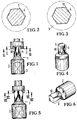
- FIG 1 shows an example of a transmission element according to the invention a screwdriver bit 1.
- a screwdriver bit 1 This contains in the example shown a base 2 with one in it arranged square recess 3 shown in dashed lines. With this square recess 3, the screwdriver bit 1 for example on a square neck of a drive tool be put on.
- a shaft 4 On the 3 facing away from the recess On the side of the base 2, a shaft 4 is formed which extends extends up to a front end 5.
- the shaft 4 is with its free end for insertion into an opening 7 of a Determines screw head 6, which is indicated in Figure 1.
- the shaft 4 has the cross-sectional shape of a regular one Hexagons on, see the sections of Figures 2 and 3 in an enlarged view Scale.
- the section of Figure 2 shows in an enlarged view Scale a section through the engagement section 8 of the screwdriver bit 1 shortly before its end 5 and the Section of Figure 3 shows the section immediately in the area the end face 9 of the screw head 6. From the comparison of the both Figures 2 and 3 shows that the shape of the cross section of the engaging portion 8 over the axial length this section 8 does not change, but the orientation changes over the length of section 8.
- the cuts Figures 2 and 3 are with the engaged portion 8 drawn.
- the edges 10 of the engagement section 8, which in the Cross-section form the corners 11, run obliquely to the longitudinal axis, but parallel to each other.
- the between the edges 10 permanent side surfaces 12 deviate from a flat shape.
- the engagement section 8 is so far in the opening 7 of the Screw head 6 inserted, as is possible. Thereby it reaches the position in the area of its free end 5, which is shown in Figure 2. In the area of the beginning of the Opening 7, that is to say on the end face 9 of the screw head 6, he takes the position shown in Figure 3. Thereby it can be seen that the engagement section 8 actually is arranged without play in the opening 7. With a "straight" extending engagement section 8 would make a cut in all Levels, for example, give a representation of Figure 2. Here, the engagement section would have a game that results from the Difference in the size of the opening and the engaging portion would result.
- edges 10 in Figure 1 run obliquely to the right or to the left.
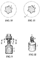
- the invention is also applicable in such cases where the transmission of the torque is not along lines or Edges, but along surfaces in the course of a cross-section takes place, as shown now with reference to Figures 9 to 12 becomes.
- the tool of FIGS. 9 to 12 is a cross section with six concave and six convex Arches that merge into each other without the formation of edges.
- Such tools are known under the Torx brand.
- Here can one can no longer speak of the edges being oblique to the Longitudinal axis run, but you can see from the side view of Figure 9 again that through the projections of the cross section formed ribs also slightly oblique to Longitudinal axis.
- the Orientation of the cross section over the length of the engagement section changes, but not the shape and size of the cross section.
Landscapes
- Engineering & Computer Science (AREA)
- Mechanical Engineering (AREA)
- Details Of Spanners, Wrenches, And Screw Drivers And Accessories (AREA)
- Shafts, Cranks, Connecting Bars, And Related Bearings (AREA)
Abstract
Description
- Fig. 1
- eine Seitenansicht eines Schraubendreherbits nach der Erfindung;
- Fig. 2
- einen Schnitt längs Linie II-II in Figur 1;
- Fig. 3
- einen der Figur 3 entsprechenden Schnitt längs Linie III-III in Figur 1;
- Fig. 4
- perspektivisch das Schraubendreherbit der Figur 1;
- Fig. 5
- eine der Figur 1 entsprechende Darstellung eines vierkantigen Schraubendreher-Einsatzes;
- Fig. 6
- eine perspektivische Darstellung des Schraubendreherbits der Figur 5;
- Fig. 7
- einen der Figur 2 entsprechenden Schnitt durch den Schraubendreher-Einsatz der Figur 5;
- Fig. 8
- einen der Figur 3 entsprechenden Schnitt durch den Schraubendreher-Einsatz der Figur 5;
- Fig. 9
- eine den Figuren 1 und 5 entsprechende Seitenansicht einer dritten Ausführungsform eines Schraubendreherbits nach der Erfindung;
- Fig. 10
- einen Schnitt längs Linie X-X in Figur 9;
- Fig. 11
- einen Schnitt längs Linie XI-XI in Figur 9;
- Fig. 12
- eine perspektivische Darstellung eines Schraubendreherbits nach Figur 9.
Claims (9)
- Übertragungselement zum Übertragen eines Drehmoments, mit1.1 einem Schaft (4) mit einem Eingriffsabschnitt (8), der1.2 zum Eingreifen in eine Öffnung (7) ausgebildet ist und1.3 eine von einer Kreisform abweichende Querschnittsform aufweist, die1.4 über die Länge des Eingriffsabschnitts (8) im Wesentlichen konstant ist, wobei1.5 sich die Orientierung der Querschnittsform über die Länge des Eingriffsabschnitts (8) ändert.
- Übertragungselement nach Anspruch 1, bei dem sich die Orientierung der Querschnittsform in nur einer Drehrichtung ändert.
- Übertragungselement nach Anspruch 1 oder 2, bei dem der Querschnitt abgerundet ausgebildet ist.
- Übertragungselement nach einem der vorhergehenden Ansprüche, bei dem der Eingriffsabschnitt (8) die Form einer tordierten Säule aufweist.
- Übertragungselement nach einem der vorhergehenden Ansprüche, bei dem der Eingriffsabschnitt (8) die Form eines tordierten Zylinders aufweist.
- Übertragungselement nach einem der Ansprüche 1, 2, 4 oder 5, bei dem der Querschnitt des Eingriffsabschnitts (8) Ecken (11) aufweist.
- Übertragungselement nach Anspruch 6, bei dem der Querschnitt des Eingriffsabschnitts (8) die Form eines regelmäßigen Vielecks aufweist.
- Übertragungselement nach einem der vorhergehenden Ansprüche, bei dem die Kanten (10) des Eingriffsabschnitts (8) schräg zur Längsrichtung verlaufen.
- Übertragungselement nach einem der vorhergehenden Ansprüche, bei dem die Länge des Eingriffsabschnitt (8) größer ist als die Tiefe der Öffnung (7).
Applications Claiming Priority (2)
| Application Number | Priority Date | Filing Date | Title |
|---|---|---|---|
| DE19926908A DE19926908A1 (de) | 1999-06-12 | 1999-06-12 | Übertragungselement zum Übertragen eines Drehmoments |
| DE19926908 | 1999-06-12 |
Publications (2)
| Publication Number | Publication Date |
|---|---|
| EP1060842A2 true EP1060842A2 (de) | 2000-12-20 |
| EP1060842A3 EP1060842A3 (de) | 2000-12-27 |
Family
ID=7911077
Family Applications (1)
| Application Number | Title | Priority Date | Filing Date |
|---|---|---|---|
| EP00111749A Withdrawn EP1060842A3 (de) | 1999-06-12 | 2000-06-02 | Übertragungselement zum Übertragen eines Drehmoments |
Country Status (2)
| Country | Link |
|---|---|
| EP (1) | EP1060842A3 (de) |
| DE (1) | DE19926908A1 (de) |
Cited By (1)
| Publication number | Priority date | Publication date | Assignee | Title |
|---|---|---|---|---|
| EP1566509A1 (de) * | 2004-02-19 | 2005-08-24 | Roto Frank Ag | Adapter sowie Verbindungselement für ein Beschlaggetriebe sowie Beschlaggetriebe für ein Fenster, eine Tür oder dergleichen |
Families Citing this family (3)
| Publication number | Priority date | Publication date | Assignee | Title |
|---|---|---|---|---|
| DE102006043784A1 (de) * | 2006-09-13 | 2008-03-27 | Aap Implantate Ag | Schraubendreher, insbesondere Sechskant-Schraubendreher, sowie Aufsteckbit |
| US20090003967A1 (en) * | 2007-06-29 | 2009-01-01 | Acument Intellectual Properties, Llc | Lobular drive system with interference fit and method and apparatus for fabricating same |
| AT13459U1 (de) * | 2011-08-29 | 2013-12-15 | Johannes Duscheck | Verwendung eines Einsatzes für ein Einschraubgerät |
Family Cites Families (8)
| Publication number | Priority date | Publication date | Assignee | Title |
|---|---|---|---|---|
| DE7200619U (de) * | 1972-04-20 | Dorma-Baubeschlag Gmbh & Co Kg | Mehrkantstiftschlüssel | |
| US2538350A (en) * | 1945-09-05 | 1951-01-16 | Gerhard H J Baule | Socket head screw |
| US3952618A (en) * | 1975-05-23 | 1976-04-27 | Honey Bee Tool Company | Extractor for plastic risers |
| DE2757488A1 (de) * | 1976-12-23 | 1978-06-29 | Roger Westin | Orientierungsgeraet fuer koerper mit polyedrischem querschnitt |
| US4191228A (en) * | 1978-06-07 | 1980-03-04 | Fenton John W | Tool assembly |
| US4970922A (en) * | 1989-03-23 | 1990-11-20 | Snap-On Tools Corporation | Torque driving tool and retainer for driven member |
| US5291811A (en) * | 1992-05-14 | 1994-03-08 | Textron Inc. | Back-side taper wedging drive system |
| DE19526631A1 (de) * | 1995-07-21 | 1997-01-30 | Otto Dipl Ing Meedt | Verwendung eines Werkzeuges |
-
1999
- 1999-06-12 DE DE19926908A patent/DE19926908A1/de not_active Withdrawn
-
2000
- 2000-06-02 EP EP00111749A patent/EP1060842A3/de not_active Withdrawn
Cited By (1)
| Publication number | Priority date | Publication date | Assignee | Title |
|---|---|---|---|---|
| EP1566509A1 (de) * | 2004-02-19 | 2005-08-24 | Roto Frank Ag | Adapter sowie Verbindungselement für ein Beschlaggetriebe sowie Beschlaggetriebe für ein Fenster, eine Tür oder dergleichen |
Also Published As
| Publication number | Publication date |
|---|---|
| EP1060842A3 (de) | 2000-12-27 |
| DE19926908A1 (de) | 2000-12-14 |
Similar Documents
| Publication | Publication Date | Title |
|---|---|---|
| DE60315637T2 (de) | Integriertes befestigungssystem | |
| EP1246578B1 (de) | Knochenschraube | |
| DE60102145T2 (de) | Antriebsköpfe für befestigungselemente | |
| DE1081724B (de) | Selbstschneidende Schraube | |
| DE102008036577A1 (de) | Schraubenantriebsausbildung | |
| DE10026205A1 (de) | Vorrichtung zum Verbinden eines Werkzeugs mit einem Antrieb | |
| WO2002000396A1 (de) | Schraubwerkzeug und verfahren zur herstellung eines schraubwerkzeuges | |
| DE19525732A1 (de) | Schraube | |
| DE10123407A1 (de) | Schraubwerkzeug und Verfahren zur Herstellung eines Schraubwerkzeuges | |
| DE19926908A1 (de) | Übertragungselement zum Übertragen eines Drehmoments | |
| DE102020005982A1 (de) | Gestängeschuss eines Erdbohrgestänges, Antriebselement, Gestängeschusssystem und Erdbohrvorrichtung | |
| DE4439973C2 (de) | Werkzeug zum Einbringen einer Schraubhülse in Baumaterial und zum Eindrehen einer Schraube in einen Aufnahmekanal der Schraubhülse | |
| EP1710452B1 (de) | System | |
| CH671260A5 (de) | ||
| EP1088625A2 (de) | Schraubendreherwerkzeug | |
| EP1498618A2 (de) | Schraube für harte Werkstoffe | |
| DE102005052694A1 (de) | Drehantriebsausbildung | |
| DE9016560U1 (de) | An einem Schraubendreher oder Schraubendrehereinsatz (Bit) vorgesehener Werkzeugendabschnitt | |
| DE102006047673B4 (de) | Einschraubwerkzeug | |
| DE2214466A1 (de) | Aus einem Schraubenzieher und Schraubengreifer bestehendes kombiniertes Werkzeug | |
| DE829126C (de) | Schraubenzieher mit verdrehbarem, schneidenfoermigem Angriffselement | |
| EP0430185A2 (de) | Griff-Dorn-Befestigungseinrichtung für die Betätigung eines Blattes, eines Tores oder dergleichen | |
| EP3800010A1 (de) | Schaltschrankschlüssel | |
| EP1072364B1 (de) | Griff für ein Werkzeug | |
| EP0378790B1 (de) | Bauelement als Teil einer Schraubverbindung |
Legal Events
| Date | Code | Title | Description |
|---|---|---|---|
| PUAI | Public reference made under article 153(3) epc to a published international application that has entered the european phase |
Free format text: ORIGINAL CODE: 0009012 |
|
| PUAL | Search report despatched |
Free format text: ORIGINAL CODE: 0009013 |
|
| AK | Designated contracting states |
Kind code of ref document: A2 Designated state(s): AT BE CH CY DE DK ES FI FR GB GR IE IT LI LU MC NL PT SE |
|
| AX | Request for extension of the european patent |
Free format text: AL;LT;LV;MK;RO;SI |
|
| AK | Designated contracting states |
Kind code of ref document: A3 Designated state(s): AT BE CH CY DE DK ES FI FR GB GR IE IT LI LU MC NL PT SE |
|
| AX | Request for extension of the european patent |
Free format text: AL;LT;LV;MK;RO;SI |
|
| AKX | Designation fees paid | ||
| STAA | Information on the status of an ep patent application or granted ep patent |
Free format text: STATUS: THE APPLICATION IS DEEMED TO BE WITHDRAWN |
|
| 18D | Application deemed to be withdrawn |
Effective date: 20010628 |
|
| REG | Reference to a national code |
Ref country code: DE Ref legal event code: 8566 |