EP1058367B1 - Batteriespeichervorrichtung - Google Patents
Batteriespeichervorrichtung Download PDFInfo
- Publication number
- EP1058367B1 EP1058367B1 EP00108803A EP00108803A EP1058367B1 EP 1058367 B1 EP1058367 B1 EP 1058367B1 EP 00108803 A EP00108803 A EP 00108803A EP 00108803 A EP00108803 A EP 00108803A EP 1058367 B1 EP1058367 B1 EP 1058367B1
- Authority
- EP
- European Patent Office
- Prior art keywords
- voltage
- charge
- battery
- cell
- current
- Prior art date
- Legal status (The legal status is an assumption and is not a legal conclusion. Google has not performed a legal analysis and makes no representation as to the accuracy of the status listed.)
- Expired - Lifetime
Links
Images


Classifications
-
- H—ELECTRICITY
- H02—GENERATION; CONVERSION OR DISTRIBUTION OF ELECTRIC POWER
- H02J—ELECTRIC POWER NETWORKS; CIRCUIT ARRANGEMENTS OR SYSTEMS FOR SUPPLYING OR DISTRIBUTING ELECTRIC POWER; SYSTEMS FOR STORING ELECTRIC ENERGY
- H02J7/00—Circuit arrangements for charging or discharging batteries or for supplying loads from batteries
- H02J7/50—Circuit arrangements for charging or discharging batteries or for supplying loads from batteries acting upon multiple batteries simultaneously or sequentially
-
- H—ELECTRICITY
- H02—GENERATION; CONVERSION OR DISTRIBUTION OF ELECTRIC POWER
- H02J—ELECTRIC POWER NETWORKS; CIRCUIT ARRANGEMENTS OR SYSTEMS FOR SUPPLYING OR DISTRIBUTING ELECTRIC POWER; SYSTEMS FOR STORING ELECTRIC ENERGY
- H02J7/00—Circuit arrangements for charging or discharging batteries or for supplying loads from batteries
- H02J7/34—Parallel operation in networks using both storage and other DC sources, e.g. providing buffering
- H02J7/35—Parallel operation in networks using both storage and other DC sources, e.g. providing buffering with light sensitive cells
-
- Y—GENERAL TAGGING OF NEW TECHNOLOGICAL DEVELOPMENTS; GENERAL TAGGING OF CROSS-SECTIONAL TECHNOLOGIES SPANNING OVER SEVERAL SECTIONS OF THE IPC; TECHNICAL SUBJECTS COVERED BY FORMER USPC CROSS-REFERENCE ART COLLECTIONS [XRACs] AND DIGESTS
- Y02—TECHNOLOGIES OR APPLICATIONS FOR MITIGATION OR ADAPTATION AGAINST CLIMATE CHANGE
- Y02E—REDUCTION OF GREENHOUSE GAS [GHG] EMISSIONS, RELATED TO ENERGY GENERATION, TRANSMISSION OR DISTRIBUTION
- Y02E10/00—Energy generation through renewable energy sources
- Y02E10/50—Photovoltaic [PV] energy
- Y02E10/56—Power conversion systems, e.g. maximum power point trackers
-
- Y—GENERAL TAGGING OF NEW TECHNOLOGICAL DEVELOPMENTS; GENERAL TAGGING OF CROSS-SECTIONAL TECHNOLOGIES SPANNING OVER SEVERAL SECTIONS OF THE IPC; TECHNICAL SUBJECTS COVERED BY FORMER USPC CROSS-REFERENCE ART COLLECTIONS [XRACs] AND DIGESTS
- Y02—TECHNOLOGIES OR APPLICATIONS FOR MITIGATION OR ADAPTATION AGAINST CLIMATE CHANGE
- Y02E—REDUCTION OF GREENHOUSE GAS [GHG] EMISSIONS, RELATED TO ENERGY GENERATION, TRANSMISSION OR DISTRIBUTION
- Y02E60/00—Enabling technologies; Technologies with a potential or indirect contribution to GHG emissions mitigation
- Y02E60/10—Energy storage using batteries
-
- Y—GENERAL TAGGING OF NEW TECHNOLOGICAL DEVELOPMENTS; GENERAL TAGGING OF CROSS-SECTIONAL TECHNOLOGIES SPANNING OVER SEVERAL SECTIONS OF THE IPC; TECHNICAL SUBJECTS COVERED BY FORMER USPC CROSS-REFERENCE ART COLLECTIONS [XRACs] AND DIGESTS
- Y02—TECHNOLOGIES OR APPLICATIONS FOR MITIGATION OR ADAPTATION AGAINST CLIMATE CHANGE
- Y02T—CLIMATE CHANGE MITIGATION TECHNOLOGIES RELATED TO TRANSPORTATION
- Y02T10/00—Road transport of goods or passengers
- Y02T10/60—Other road transportation technologies with climate change mitigation effect
- Y02T10/70—Energy storage systems for electromobility, e.g. batteries
Definitions
- the present invention relates to a battery accumulating apparatus for use in a low altitude satellite use power supply apparatus, an electric motorcar use power supply apparatus, or the like.
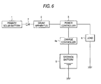
- Fig. 6 is a structural view of the low altitude satellite use power supply apparatus using a conventional storage battery such as a Ni-Cd (Nickel Cadmium) battery.
- numeral 1 is a solar battery
- numeral 2 is a shunt apparatus to consume surplus power generated in the solar battery
- numeral 3 is a power controller into which a current from the solar battery 1 is inputted through the shunt apparatus 2, and which supplies a current to a charging controller 4a and a load 6, and when the generated power of the solar battery 1 is lowered, which controls the charge controller 4a so that the current is supplied to the load 6 by discharging the storage battery 5.
- the charge controller 4a is a charge controller which receives an output from the power controller 3 and supplies a current to the storage battery 5 for charging, and discharges the storage battery 5 by a signal outputted when the generated power of the solar battery 1 is lowered.
- Numeral 7 is a reverse-current prevention diode.
- a current from a solar battery 1 is inputted into a power controller 3 through a reverse-current prevention diode 7 and a shunt apparatus 2.
- the power controller 3 supplies the current obtained from the solar battery 1 in shining hours to a load 6 and a charge controller 4a.
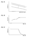
- the charge controller 4a generates a prescribed value of current IO shown in Fig. 7C by power from the power controller 3, supplies the current IO to a storage battery 5, and charges the storage battery 5.
- the voltage of the storage battery 5 increases as shown in Fig. 7B as the charging process advances.
- the charge controller 4a detects that the voltage of the storage battery 5 reaches a predetermined temperature-compensated voltage value as shown in Fig.
- the charge controller 4a discharges the storage battery 5 by the output of the power controller 3, and supplies the power to the load 6.
- the charge of the storage battery in the conventional low altitude satellite use power supply apparatus is performed as described above, however, the constant-voltage/constant-current charge as described above is conducted on the overall storage battery in which n battery cells are cascade-connected in series, therefore, there is a problem that a specific cell in the storage battery is overcharged due to the unbalance in charge characteristics of each cell constituting the storage battery.
- Li-Ion (Lithium Ion) cell structured by Li (Lithium) electrode
- energy density, charging voltage, discharging voltage, etc. are higher as compared to those of a Ni-Cd cell, and the Li-Ion cell is expected for use in the storage battery
- the sum of n cell voltage is detected as the storage battery voltage, and compared to the setting voltage, however, when m-th cell voltage is higher than that of the other cells due to the internal resistance of the cell, the voltage exceeds the upper limit of the cell voltage, sometimes resulting in deterioration of the cell.
- the present invention is achieved to solve such the problem and the object of the present invention is to obtain the battery accumulating apparatus by which an appropriate charge amount can be secured without overcharging each cell constituting the storage battery.
- a known battery accumulating apparatus comprises a storage battery to which battery cells are cascade-connected, and a charge current generating means having a means which generates different and a plurality of charge currents to charge the storage battery from the power supply output, and supplies different and a plurality of charge currents to the storage battery, such as disclosed in US 5,677,613 .
- the charge current generating means is provided with a means for generating different and a plurality of charge currents, and for changing the charge current so as to be supplied at a low level after, initially, the charge current is supplied at a high level.
- the charge current generating means is provided with a means for changing the charge current from a high level to a low level when any of voltage of battery cells reaches a prescribed value.
- a shunt circuit is respectively connected to each battery cell, and when any of voltage of battery cells reaches a prescribed value under the lowest level charge current supply condition to the storage battery, the charge current flowing to the battery cell is bypassed to the shunt circuit connected to the battery cell.
- a battery accumulating apparatus of the present invention may comprise a switch between the power supply and the storage battery; the switch normally being turned ON; and being turned OFF by the charge current generating means when any of voltage of battery cells reaches a prescribed value; and being returned to ON by discharge.
- the charge current generating means is provided with a means which detects the voltage of the overall battery cell, and which shifts to constant-voltage charge control when the detected voltage reaches a prescribed value.
- the charge current generating means is provided with a means which releases the constant-voltage charge control when the voltage of the plurality of battery cells becomes unbalanced, and charges the battery cells by the low level charge current until the voltage of the battery cells reaches a prescribed value.
- a Li-Ion (lithium ion) battery cell structured by a Li (lithium) electrode can be used as the battery cell.
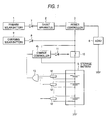
- Fig. 1 is a structural view of a low altitude satellite use power supply apparatus showing aspects of the present invention.
- numerals 1, 2, 3, 5, 6 and 7 are the same as those in Fig. 6 .
- Numeral 4b is a charge controller to generate a plurality of charge currents according to the output of a charging solar battery 9, and to supply different and a plurality of charge currents to a storage battery to which battery cells are cascade-connected;
- numeral 8 is a reverse-flow prevention diode connected between the charging solar battery 9 and the storage battery 5;
- numeral 10 is a switch connected between the storage battery 5 and the reverse-flow prevention diode 8, and is ON status when charging is started, and charging is directly conducted from the charging solar battery 9 to the storage battery 5.
- Numeral 11 is a control diode.
- the charge controller 4b has a current control section to generate charge currents I2 and I3 (I2 > I3) whose levels are lower than a charge current I1 according to the output of the charging solar battery 9.
- Numeral 12 is a plurality of cell voltage detectors to detect voltage of each battery cell, and to output a predetermined signal when the detected voltage of the battery cell reaches a prescribed value
- numeral 13 is an OR circuit which is connected to output terminals of the plurality of cell voltage detectors 12, and outputs a predetermined signal from the cell voltage detectors 12 to the charge controller 4b.
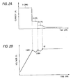
- each battery cell of the storage battery 5 is charged, and voltage of each battery cell increases as shown by A in Fig. 2B .
- the cell voltage detector 12 respectively detects voltage of the battery cell, and when any of cell voltage of the plurality of battery cells reaches a prescribed value (for example, 3.98 V), the cell voltage detector 12 which detects the cell voltage, outputs a High level signal, for example, to the OR circuit 13.
- the charge controller 4b When the High level signal outputted from the cell voltage detector 12 is inputted through the OR circuit 13, the charge controller 4b outputs a signal which switches the switch 10 in the ON status to the OFF status, to the switch 10 through the control diode 11 and turns the switch 10 OFF. Further, the charge controller 4b turns the switch 10 OFF when the voltage of overall battery cells reaches a prescribed value (for example, 3.95 V x the number of battery cells), and shifts the charging mode to the constant-voltage charge.
- a prescribed value for example, 3.95 V x the number of battery cells
- the charge controller 4b has a function to generate the charge currents I2 and I3 (I2 > I3) whose levels are lower than the charge current I1, according to the output from the charging solar buttery 9 (a function by which the charge current I1 is switched to the charge currents I2 and I3), and supplies the charge current I2 (refer to I2 in Fig. 2A ), for example, 5A to the storage battery 5 at the same time as the turning OFF of the switch 10, and charges each battery cell. At this time, the charge voltage of each battery cell initially decreases as shown by B in Fig. 2B , and in a short time, it increases.
- Each battery cell is charged by the charge current I2 and when any cell voltage of the plurality of battery cells reaches a prescribed value (for example, 3.98 V), the voltage is detected by the cell voltage detector 12, and the detection signal is inputted into the charge controller 4b through the OR circuit 13.
- the charge controller 4b receives the signal from the cell voltage detector 12, and switches the charge current I2 to I3 and supplies the charge current I3 (for example, 1 A) shown in Fig. 2A to the storage battery 5, and charges each battery cell (refer to C in Fig. 2B ).
- the charge controller 4b outputs a signal to return the switch 10 to the ON status at the time of discharge of the storage battery 5, to the switch 10 through the control diode 11.
- the present invention is provided with a multi-stage charge function which supplies the different and plurality of charge currents to the storage battery, and after supplies the charge current initially at a high level, next supplies the charge current at low level, and therefore, the charge controller may control the charge current whose level is lower than the power of the charging solar battery, therefore, there are effects that the charging efficiency is increased and the size and weight can be reduced.
- the charge control can be more precisely conducted.
- Fig. 3 is a structural view of a low altitude satellite use power supply apparatus showing an Embodiment not of the present invention, but useful to understand the invention.
- This Embodiment is characterized in that the shunt circuit 14 is connected in parallel to each battery cell in the structure of Embodiment 2, and when the voltage of the battery cell reaches a prescribed value, the charge current is bypassed to the shunt circuit 14 connected in parallel to the battery cell whose voltage reaches the prescribed value so that the voltage increase of the battery cell is suppressed.
- the cell voltage detector 12 outputs a Low level signal when the voltage of the battery cell does not reach a prescribed value.
- the shunt circuit 14 is in OFF status when the Low level signal is outputted, and the charge current I3 flows the battery cell.
- the cell voltage detector 12 outputs a High level signal when the voltage of the battery cell reaches the prescribed value.
- the shunt circuit 14 is turned to ON status by this High level signal. According to that, the charge current is bypassed to the shunt circuit 14 connected in parallel to the battery cell whose voltage reaches the prescribed value and consumed, thereby, the charge current I3 does not flow to the battery cell, and the voltage increase can be suppressed.
- the upper limit voltage can be controlled for each battery cell, and cycle life deterioration of the battery cell can be suppressed to the minimum.
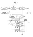
- Fig. 4 is a structural view of the low altitude satellite use power supply apparatus showing an Embodiment not of the present invention, but useful to understand the invention.
- This Embodiment is basically the same as the former Embodiment, however, the different points from the former Embodiment are as follows: a signal diode 15 to output a signal to turn OFF the switch 10 according to the output of the OR circuit 13, and a charge controller 4c having a function in which, when the storage battery is charged by the charge current I3, the voltage of the overall battery is monitored, and when the voltage reaches a prescribed value (which is set lower than the predetermined voltage to switch the charge current), the constant-current charge is shifted (switched) to the constant-voltage charge, are provided.
- a prescribed value which is set lower than the predetermined voltage to switch the charge current
- the constant-voltage charge is carried out when the voltage of each battery cell is balanced, and is an ideal condition as a battery operation.
- the charge controller is provided with a function which monitors the voltage of the overall storage battery when the storage battery is charged by the charge current I1, and which switches the charging mode from the constant-current charge to the constant-voltage charge when the voltage reaches a prescribed value (for example, 3.95 V x the number of batteries), and by using both of this function and the multi-stage charge together, when voltage characteristics of the battery cell are balanced, the charge control is conducted without operating the shunt circuit as much as possible, thereby, the predetermined voltage can be suppressed low, and the cycle life deterioration of the battery cell can be suppressed low.
- a prescribed value for example, 3.95 V x the number of batteries
- Fig. 5 is a structural view of the low altitude satellite use power supply apparatus showing an Embodiment of the present invention.
- This Embodiment is basically the same as the former Embodiment, however, the different points from the former Embodiment are as follows: a charge controller 4d having a function in which, after the constant-current charge is shifted to the constant-voltage charge, when the voltage of each battery cell is unbalanced, the constant-voltage charge control is released, and the voltage balance of each battery cell is taken by forcibly charging each battery cell to the voltage by which the shunt circuit 12 is operated(to the shunt voltage)by the charge current I3, is provided.
- the voltage of each battery cell is detected by the cell voltage detector 12 and inputted into the charge controller 4d through the OR circuit 13, and existence of the voltage unbalance of each battery cell (voltage fluctuation among battery cells to the predetermined voltage) is detected in the charge controller 4d, however, the voltage of each battery cell is monitored on the ground station side, and when the unbalance is generated, a command to release the constant-voltage charge control, and to forcibly charge each battery cell to the voltage, by which the shunt circuit 12 is operated, by the charge current I3, may be outputted to the charge controller 4d.
- the constant-current charge is shifted to the constant-voltage charge
- the constant-voltage charge control is released, and each battery cell is charged to the shunt operation voltage by the charge current I3, thereby, the voltage unbalance of each battery cell generated as the charge cycle advances, can be corrected.
- the low altitude satellite use power supply apparatus is described as an embodiment, however, the present invention can also be applied to other satellites, electric motorcars, ground use solar power generation, etc.
- the overcharge of the battery cells can be suppressed.
- the charge current flowing to the battery cell is bypassed to the shunt circuit connected to the battery cell, thereby, the overcharge of the battery cell can be suppressed.
- the voltage of the overall battery under the condition that the voltage of each battery cell is balanced, is monitored, and when the voltage reaches a prescribed value, the constant-current charge is switched to the constant-voltage charge, thereby, the battery operation can be made ideal condition so that the cycle life deterioration is suppressed.
- the constant-current charge is shifted to the constant-voltage charge
- the constant-voltage charge control is released, and each battery cell is charged to the shunt operation voltage, thereby, the voltage unbalance of each battery cell can be corrected.
Landscapes
- Engineering & Computer Science (AREA)
- Power Engineering (AREA)
- Charge And Discharge Circuits For Batteries Or The Like (AREA)
- Secondary Cells (AREA)
Claims (3)
- Batteriespeichervorrichtung, welche aufweist:eine Speicherbatterie (5), mit der Batteriezellen in Kaskade verbunden sind; undeine Ladestrom-Erzeugungsvorrichtung (9, 4, 10), die ausgebildet ist zum Erzeugen eines Stroms zur Ladung der Speicherbatterie von einem Stromversorgungsausgang;wobei die Ladestrom-Erzeugungsvorrichtung ein Mittel hat, das ausgebildet ist zum Erzeugen mehrerer unterschiedlicher Ladeströme und zum Liefern mehrerer unterschiedlicher Ladeströme zu der Speicherbatterie,dadurch gekennzeichnet, dass die Ladestrom-Erzeugungsvorrichtung ein Mittel (12, 13) hat, das ausgebildet ist zum Erfassen einer Spannung der gesamten Batteriezellen, unddas ausgebildet ist zum Verschieben zu einer Konstantspannungs-Ladesteuerung, wenn die erfasste Spannung einen vorgeschriebenen Wert erreicht, unddie Ladestrom-Erzeugungsvorrichtung ein Mittel (4d) hat, das ausgebildet ist zum Freigeben der Konstantspannungs-Ladesteuerung, wenn eine Spannung der mehreren Batteriezellen aus dem Gleichgewicht gerät, und zum Laden der Batteriezellen durch einen Ladestrom mit niedrigen Pegel, bis die Spannung sämtlicher Batteriezellen den vorgeschriebenen Wert erreicht.
- Batteriespeichervorrichtung nach Anspruch 1, bei der ein Schalter (10) zwischen der Versorgungsquelle und der Speicherbatterie vorgesehen ist; wobei der Schalter ausgebildet ist, normalerweise EIN-geschaltet zu sein, durch die Ladestrom-Erzeugungsvorrichtung AUS-geschaltet zu werden, wenn irgendeine Spannung von Batteriezellen einen vorgeschriebenen Wert erreicht, und zu der Zeit der Entladung zum EIN-Schaltzustand zurückzukehren.
- Batteriespeichervorrichtung nach Anspruch 1, bei der eine Li-Ionen(Lithiumionen)-Batteriezelle, die durch eine Li(Lithium)-Elektrode strukturiert ist, als die Batteriezelle verwendet wird.
Applications Claiming Priority (2)
| Application Number | Priority Date | Filing Date | Title |
|---|---|---|---|
| JP15779799 | 1999-06-04 | ||
| JP15779799A JP3736205B2 (ja) | 1999-06-04 | 1999-06-04 | バッテリ蓄電装置 |
Publications (3)
| Publication Number | Publication Date |
|---|---|
| EP1058367A2 EP1058367A2 (de) | 2000-12-06 |
| EP1058367A3 EP1058367A3 (de) | 2002-11-20 |
| EP1058367B1 true EP1058367B1 (de) | 2011-06-15 |
Family
ID=15657506
Family Applications (1)
| Application Number | Title | Priority Date | Filing Date |
|---|---|---|---|
| EP00108803A Expired - Lifetime EP1058367B1 (de) | 1999-06-04 | 2000-04-26 | Batteriespeichervorrichtung |
Country Status (5)
| Country | Link |
|---|---|
| US (1) | US6373224B1 (de) |
| EP (1) | EP1058367B1 (de) |
| JP (1) | JP3736205B2 (de) |
| CA (1) | CA2310357C (de) |
| FR (1) | FR2794578B1 (de) |
Families Citing this family (50)
| Publication number | Priority date | Publication date | Assignee | Title |
|---|---|---|---|---|
| JP2002186192A (ja) | 2000-12-18 | 2002-06-28 | Mitsubishi Electric Corp | バッテリ充電器 |
| US8535396B2 (en) | 2002-08-09 | 2013-09-17 | Infinite Power Solutions, Inc. | Electrochemical apparatus with barrier layer protected substrate |
| US8445130B2 (en) | 2002-08-09 | 2013-05-21 | Infinite Power Solutions, Inc. | Hybrid thin-film battery |
| US20070264564A1 (en) | 2006-03-16 | 2007-11-15 | Infinite Power Solutions, Inc. | Thin film battery on an integrated circuit or circuit board and method thereof |
| US8404376B2 (en) | 2002-08-09 | 2013-03-26 | Infinite Power Solutions, Inc. | Metal film encapsulation |
| US8236443B2 (en) | 2002-08-09 | 2012-08-07 | Infinite Power Solutions, Inc. | Metal film encapsulation |
| US8431264B2 (en) | 2002-08-09 | 2013-04-30 | Infinite Power Solutions, Inc. | Hybrid thin-film battery |
| US8394522B2 (en) | 2002-08-09 | 2013-03-12 | Infinite Power Solutions, Inc. | Robust metal film encapsulation |
| US8021778B2 (en) | 2002-08-09 | 2011-09-20 | Infinite Power Solutions, Inc. | Electrochemical apparatus with barrier layer protected substrate |
| US8728285B2 (en) | 2003-05-23 | 2014-05-20 | Demaray, Llc | Transparent conductive oxides |
| TWI253195B (en) * | 2003-12-26 | 2006-04-11 | Ind Tech Res Inst | Charging method and system for serially connected batteries |
| WO2006063308A2 (en) | 2004-12-08 | 2006-06-15 | Symmorphix, Inc. | DEPOSITION OF LICoO2 |
| US7959769B2 (en) | 2004-12-08 | 2011-06-14 | Infinite Power Solutions, Inc. | Deposition of LiCoO2 |
| JP2007014163A (ja) * | 2005-07-01 | 2007-01-18 | Fujitsu Ltd | 充電用ic、充電装置及び電子機器 |
| JP2007097330A (ja) | 2005-09-29 | 2007-04-12 | Kyocera Corp | 充電装置及び端末装置 |
| US7509688B2 (en) * | 2005-10-20 | 2009-03-31 | Steven Ross Gregg | Facial hair trimmings catcher |
| US8062708B2 (en) | 2006-09-29 | 2011-11-22 | Infinite Power Solutions, Inc. | Masking of and material constraint for depositing battery layers on flexible substrates |
| US8197781B2 (en) | 2006-11-07 | 2012-06-12 | Infinite Power Solutions, Inc. | Sputtering target of Li3PO4 and method for producing same |
| US20080218127A1 (en) * | 2007-03-07 | 2008-09-11 | O2Micro Inc. | Battery management systems with controllable adapter output |
| KR101407941B1 (ko) * | 2007-04-16 | 2014-06-18 | 한라비스테온공조 주식회사 | 차량용 태양전지 시스템 및 그 제어방법 |
| JP2009032668A (ja) * | 2007-06-22 | 2009-02-12 | Panasonic Corp | 非水系二次電池、電池パック、電源システム、及び電動機器 |
| WO2009001502A1 (ja) * | 2007-06-22 | 2008-12-31 | Panasonic Corporation | 非水系二次電池、電池パック、電源システム、及び電動機器 |
| KR100998302B1 (ko) | 2007-12-07 | 2010-12-06 | 삼성에스디아이 주식회사 | 이차 전지의 충전 방법 및 충전 장치 |
| US8268488B2 (en) * | 2007-12-21 | 2012-09-18 | Infinite Power Solutions, Inc. | Thin film electrolyte for thin film batteries |
| WO2009086038A1 (en) | 2007-12-21 | 2009-07-09 | Infinite Power Solutions, Inc. | Method for sputter targets for electrolyte films |
| EP2229706B1 (de) * | 2008-01-11 | 2014-12-24 | Infinite Power Solutions, Inc. | Dünnfilmeinkapselung für dünnfilmbatterien und andere geräte |
| WO2009124191A2 (en) * | 2008-04-02 | 2009-10-08 | Infinite Power Solutions, Inc. | Passive over/under voltage control and protection for energy storage devices associated with energy harvesting |
| US20100026240A1 (en) * | 2008-07-30 | 2010-02-04 | 3M Innovative Properties Company | Lithium ion battery pack charging system and device including the same |
| EP2319101B1 (de) | 2008-08-11 | 2015-11-04 | Sapurast Research LLC | Stromvorrichtung mit integrierter sammelfläche zur gewinnung elektomagnetischer energie sowie verfahren dafür |
| JP2010068571A (ja) * | 2008-09-09 | 2010-03-25 | Hitachi Koki Co Ltd | 充電装置 |
| KR101613671B1 (ko) | 2008-09-12 | 2016-04-19 | 사푸라스트 리써치 엘엘씨 | 전자기 에너지에 의해 데이터 통신을 하는 통합 도전성 표면을 가진 에너지 장치 및 그 통신 방법 |
| WO2010042594A1 (en) | 2008-10-08 | 2010-04-15 | Infinite Power Solutions, Inc. | Environmentally-powered wireless sensor module |
| JPWO2010079563A1 (ja) * | 2009-01-07 | 2012-06-21 | パナソニック株式会社 | 組電池の充電方法、及び電池充電システム |
| US20100231162A1 (en) * | 2009-03-16 | 2010-09-16 | Gm Global Technology Operations, Inc. | Solar powered battery charging methods and devices for lithium-ion battery systems |
| CN102576828B (zh) | 2009-09-01 | 2016-04-20 | 萨普拉斯特研究有限责任公司 | 具有集成薄膜电池的印刷电路板 |
| JP5489779B2 (ja) * | 2010-02-26 | 2014-05-14 | 株式会社Nttファシリティーズ | リチウムイオン組電池の充電システムおよび充電方法 |
| JP5525862B2 (ja) * | 2010-02-26 | 2014-06-18 | 三洋電機株式会社 | 充電装置、プログラム |
| US9722334B2 (en) * | 2010-04-07 | 2017-08-01 | Black & Decker Inc. | Power tool with light unit |
| KR101930561B1 (ko) | 2010-06-07 | 2018-12-18 | 사푸라스트 리써치 엘엘씨 | 재충전 가능한 고밀도 전기 화학 장치 |
| JP5541982B2 (ja) * | 2010-06-28 | 2014-07-09 | シャープ株式会社 | 直流配電システム |
| TWM402554U (en) * | 2010-11-10 | 2011-04-21 | Richtek Technology Corp | Charger circuit |
| JP2012222837A (ja) * | 2011-04-04 | 2012-11-12 | Toshiba Mitsubishi-Electric Industrial System Corp | 二次電池充電制御システム |
| DE102011017599A1 (de) * | 2011-04-27 | 2012-10-31 | Robert Bosch Gmbh | Verfahren zum Betreiben einer Speichervorrichtung zum Speichern von elektrischer Energie und Speichervorrichtung zum Speichern von elektrischer Energie |
| WO2012177193A1 (en) * | 2011-06-21 | 2012-12-27 | Husqvarna Ab | System and method for charging of a rechargeable battery |
| DE102011121940A1 (de) * | 2011-12-22 | 2013-06-27 | Andreas Stihl Ag & Co. Kg | Debalancierungs-Schutzschaltung für einen Akkupack |
| US8981709B1 (en) * | 2012-08-22 | 2015-03-17 | Edee, LLC | Supplemental electrical generation apparatus and method |
| US9156359B2 (en) | 2012-09-28 | 2015-10-13 | GM Global Technology Operations LLC | Methods and vehicle systems for selectively using energy obtained from a solar subsystem |
| CN103023112B (zh) * | 2012-12-18 | 2015-09-09 | 北车风电有限公司 | 风力发电机组变桨系统的后备电源充电装置及充电方法 |
| FR3033674B1 (fr) | 2015-03-10 | 2018-04-06 | Sunna Design | Carte electronique de pilotage energetique d'un equipement electrique autonome et communicant |
| JP7200512B2 (ja) * | 2018-06-21 | 2023-01-10 | カシオ計算機株式会社 | 電子機器、電子時計および電池充電方法 |
Family Cites Families (26)
| Publication number | Priority date | Publication date | Assignee | Title |
|---|---|---|---|---|
| US4079303A (en) | 1976-07-28 | 1978-03-14 | The United States Of America As Represented By The United States Department Of Energy | Charging system and method for multicell storage batteries |
| US4270080A (en) | 1978-12-14 | 1981-05-26 | Sun Electric Corporation | Automatic battery charge apparatus and method |
| JPS5972941A (ja) | 1982-10-20 | 1984-04-25 | 日本電気株式会社 | 蓄電池充電制御装置 |
| JP3231801B2 (ja) * | 1991-02-08 | 2001-11-26 | 本田技研工業株式会社 | バッテリの充電装置 |
| JPH06133465A (ja) | 1992-08-27 | 1994-05-13 | Sanyo Electric Co Ltd | 二次電池の充電方法及び充電装置 |
| JPH06165399A (ja) | 1992-11-24 | 1994-06-10 | Nippon Moriseru Kk | リチュウム・イオン二次電池の充電装置 |
| US5367244A (en) * | 1993-01-19 | 1994-11-22 | Premier Engineered Products, Inc. | Battery charging method with stepped current profile and associated charger |
| US5530335A (en) * | 1993-05-11 | 1996-06-25 | Trw Inc. | Battery regulated bus spacecraft power control system |
| JP3577751B2 (ja) | 1993-12-24 | 2004-10-13 | ソニー株式会社 | バッテリー充電装置、バッテリーパック及びバッテリー充電方法 |
| US5550453A (en) | 1994-01-24 | 1996-08-27 | Motorola, Inc. | Battery charging method and apparatus |
| FR2725849B1 (fr) * | 1994-10-18 | 1996-12-20 | Accumulateurs Fixes | Procede de regulation de la charge d'un ensemble accumulateur electrique et agencement mettant en oeuvre ce procede |
| CA2169706A1 (en) * | 1995-03-03 | 1996-09-04 | Troy Lynn Stockstad | Circuit and method for battery charge control |
| JPH0997629A (ja) | 1995-09-29 | 1997-04-08 | Sanyo Electric Co Ltd | 複数のリチウムイオン二次電池の充電方法 |
| JP3620118B2 (ja) | 1995-10-24 | 2005-02-16 | 松下電器産業株式会社 | 定電流・定電圧充電装置 |
| JP3629791B2 (ja) * | 1996-01-17 | 2005-03-16 | 日産自動車株式会社 | 組電池の充電制御装置 |
| GB9605830D0 (en) | 1996-03-20 | 1996-05-22 | Atomic Energy Authority Uk | Cell overcharge prevention |
| JPH09308126A (ja) | 1996-05-17 | 1997-11-28 | Nissan Motor Co Ltd | 充電装置 |
| US5729116A (en) * | 1996-12-20 | 1998-03-17 | Total Battery Management, Inc. | Shunt recognition in lithium batteries |
| JP3884802B2 (ja) | 1996-11-07 | 2007-02-21 | 日産自動車株式会社 | リチウムイオン電池の充電方法 |
| JPH10191574A (ja) * | 1996-12-26 | 1998-07-21 | Japan Tobacco Inc | 充電装置 |
| JPH10248177A (ja) | 1997-03-03 | 1998-09-14 | Sanyo Electric Co Ltd | 充電回路 |
| US5804944A (en) | 1997-04-07 | 1998-09-08 | Motorola, Inc. | Battery protection system and process for charging a battery |
| US5952815A (en) * | 1997-07-25 | 1999-09-14 | Minnesota Mining & Manufacturing Co. | Equalizer system and method for series connected energy storing devices |
| JPH1189106A (ja) | 1997-09-08 | 1999-03-30 | Central Res Inst Of Electric Power Ind | 二次電池の多段充電方法及びその装置 |
| US6034506A (en) * | 1998-01-16 | 2000-03-07 | Space Systems/Loral, Inc. | Lithium ion satellite battery charge control circuit |
| JP2000236631A (ja) | 1999-02-17 | 2000-08-29 | Nec Corp | 電池充電制御回路 |
-
1999
- 1999-06-04 JP JP15779799A patent/JP3736205B2/ja not_active Expired - Fee Related
- 1999-11-19 US US09/443,286 patent/US6373224B1/en not_active Expired - Fee Related
- 1999-11-30 FR FR9915100A patent/FR2794578B1/fr not_active Expired - Fee Related
-
2000
- 2000-04-26 EP EP00108803A patent/EP1058367B1/de not_active Expired - Lifetime
- 2000-05-31 CA CA002310357A patent/CA2310357C/en not_active Expired - Fee Related
Also Published As
| Publication number | Publication date |
|---|---|
| EP1058367A3 (de) | 2002-11-20 |
| US6373224B1 (en) | 2002-04-16 |
| JP3736205B2 (ja) | 2006-01-18 |
| JP2000350378A (ja) | 2000-12-15 |
| FR2794578A1 (fr) | 2000-12-08 |
| CA2310357C (en) | 2004-02-17 |
| FR2794578B1 (fr) | 2003-10-17 |
| CA2310357A1 (en) | 2000-12-04 |
| EP1058367A2 (de) | 2000-12-06 |
Similar Documents
| Publication | Publication Date | Title |
|---|---|---|
| EP1058367B1 (de) | Batteriespeichervorrichtung | |
| US8183818B2 (en) | Switching time control multiplexer system | |
| EP2605359B1 (de) | Batteriesystem und sein steuerungsverfahren | |
| US7719231B2 (en) | Equilibrated charging method for a lithium-ion or lithium-polymer battery | |
| US20130187466A1 (en) | Power management system | |
| US11063447B2 (en) | Battery pack and energy storage system comprising same | |
| US7928691B2 (en) | Method and system for cell equalization with isolated charging sources | |
| EP2249454A1 (de) | Aufladevorrichtung und aufladeverfahren | |
| JP3931446B2 (ja) | 組電池の充電状態調整装置 | |
| KR101312263B1 (ko) | 운송 수단 및 그 제어 방법 | |
| JPH0997629A (ja) | 複数のリチウムイオン二次電池の充電方法 | |
| JP5508771B2 (ja) | 組電池、及び電池システム | |
| JP3419115B2 (ja) | 組電池の充放電保護装置 | |
| JP2002058170A (ja) | 無停電電源装置 | |
| JP2001008373A (ja) | バッテリー装置及びバッテリーの充電方法 | |
| JP3177405B2 (ja) | 二次電池の充放電制御方法及び装置 | |
| JP3421534B2 (ja) | 過充電防止回路、過放電防止回路及び充放電制御回路 | |
| JP4485489B2 (ja) | 直流電源システムとその試験方法ならびに直流電源システムの試験方法を実行するためのプログラム | |
| JP2000004544A (ja) | 独立型太陽光発電電力供給制御方法及びシステム装置 | |
| JP3583303B2 (ja) | 多段接続二次電池の充放電制御方法及びその装置 | |
| RU2724111C1 (ru) | Система электропитания космического аппарата | |
| KR20230022012A (ko) | 배터리의 열화 저감방법 및 그 방법을 제공하는 배터리 관리 시스템 | |
| JP2000341875A (ja) | 太陽光発電装置 | |
| RU2852591C1 (ru) | Способ управления работой системы электроснабжения космического аппарата | |
| RU211054U1 (ru) | Система электропитания космического аппарата |
Legal Events
| Date | Code | Title | Description |
|---|---|---|---|
| PUAI | Public reference made under article 153(3) epc to a published international application that has entered the european phase |
Free format text: ORIGINAL CODE: 0009012 |
|
| AK | Designated contracting states |
Kind code of ref document: A2 Designated state(s): AT BE CH CY DE DK ES FI FR GB GR IE IT LI LU MC NL PT SE |
|
| AX | Request for extension of the european patent |
Free format text: AL;LT;LV;MK;RO;SI |
|
| PUAL | Search report despatched |
Free format text: ORIGINAL CODE: 0009013 |
|
| AK | Designated contracting states |
Kind code of ref document: A3 Designated state(s): AT BE CH CY DE DK ES FI FR GB GR IE IT LI LU MC NL PT SE |
|
| AX | Request for extension of the european patent |
Free format text: AL;LT;LV;MK;RO;SI |
|
| 17P | Request for examination filed |
Effective date: 20030131 |
|
| AKX | Designation fees paid |
Designated state(s): DE IT |
|
| RAP1 | Party data changed (applicant data changed or rights of an application transferred) |
Owner name: MITSUBISHI DENKI KABUSHIKI KAISHA |
|
| 17Q | First examination report despatched |
Effective date: 20070829 |
|
| GRAP | Despatch of communication of intention to grant a patent |
Free format text: ORIGINAL CODE: EPIDOSNIGR1 |
|
| GRAS | Grant fee paid |
Free format text: ORIGINAL CODE: EPIDOSNIGR3 |
|
| GRAA | (expected) grant |
Free format text: ORIGINAL CODE: 0009210 |
|
| AK | Designated contracting states |
Kind code of ref document: B1 Designated state(s): DE IT |
|
| REG | Reference to a national code |
Ref country code: DE Ref legal event code: R096 Ref document number: 60046063 Country of ref document: DE Effective date: 20110721 |
|
| PLBE | No opposition filed within time limit |
Free format text: ORIGINAL CODE: 0009261 |
|
| STAA | Information on the status of an ep patent application or granted ep patent |
Free format text: STATUS: NO OPPOSITION FILED WITHIN TIME LIMIT |
|
| 26N | No opposition filed |
Effective date: 20120316 |
|
| REG | Reference to a national code |
Ref country code: DE Ref legal event code: R097 Ref document number: 60046063 Country of ref document: DE Effective date: 20120316 |
|
| PGFP | Annual fee paid to national office [announced via postgrant information from national office to epo] |
Ref country code: DE Payment date: 20120430 Year of fee payment: 13 |
|
| PGFP | Annual fee paid to national office [announced via postgrant information from national office to epo] |
Ref country code: IT Payment date: 20120424 Year of fee payment: 13 |
|
| PG25 | Lapsed in a contracting state [announced via postgrant information from national office to epo] |
Ref country code: DE Free format text: LAPSE BECAUSE OF NON-PAYMENT OF DUE FEES Effective date: 20131101 |
|
| REG | Reference to a national code |
Ref country code: DE Ref legal event code: R119 Ref document number: 60046063 Country of ref document: DE Effective date: 20131101 |
|
| PG25 | Lapsed in a contracting state [announced via postgrant information from national office to epo] |
Ref country code: IT Free format text: LAPSE BECAUSE OF NON-PAYMENT OF DUE FEES Effective date: 20130426 |