EP1055898A2 - Echangeur de chaleur en alliage d'aluminium - Google Patents
Echangeur de chaleur en alliage d'aluminium Download PDFInfo
- Publication number
- EP1055898A2 EP1055898A2 EP00110962A EP00110962A EP1055898A2 EP 1055898 A2 EP1055898 A2 EP 1055898A2 EP 00110962 A EP00110962 A EP 00110962A EP 00110962 A EP00110962 A EP 00110962A EP 1055898 A2 EP1055898 A2 EP 1055898A2
- Authority
- EP
- European Patent Office
- Prior art keywords
- aluminum alloy
- core
- tubes
- work
- layer
- Prior art date
- Legal status (The legal status is an assumption and is not a legal conclusion. Google has not performed a legal analysis and makes no representation as to the accuracy of the status listed.)
- Withdrawn
Links
Images


Classifications
-
- F—MECHANICAL ENGINEERING; LIGHTING; HEATING; WEAPONS; BLASTING
- F28—HEAT EXCHANGE IN GENERAL
- F28F—DETAILS OF HEAT-EXCHANGE AND HEAT-TRANSFER APPARATUS, OF GENERAL APPLICATION
- F28F19/00—Preventing the formation of deposits or corrosion, e.g. by using filters or scrapers
- F28F19/02—Preventing the formation of deposits or corrosion, e.g. by using filters or scrapers by using coatings, e.g. vitreous or enamel coatings
- F28F19/06—Preventing the formation of deposits or corrosion, e.g. by using filters or scrapers by using coatings, e.g. vitreous or enamel coatings of metal
-
- B—PERFORMING OPERATIONS; TRANSPORTING
- B23—MACHINE TOOLS; METAL-WORKING NOT OTHERWISE PROVIDED FOR
- B23K—SOLDERING OR UNSOLDERING; WELDING; CLADDING OR PLATING BY SOLDERING OR WELDING; CUTTING BY APPLYING HEAT LOCALLY, e.g. FLAME CUTTING; WORKING BY LASER BEAM
- B23K1/00—Soldering, e.g. brazing, or unsoldering
- B23K1/0008—Soldering, e.g. brazing, or unsoldering specially adapted for particular articles or work
- B23K1/0012—Brazing heat exchangers
-
- F—MECHANICAL ENGINEERING; LIGHTING; HEATING; WEAPONS; BLASTING
- F28—HEAT EXCHANGE IN GENERAL
- F28D—HEAT-EXCHANGE APPARATUS, NOT PROVIDED FOR IN ANOTHER SUBCLASS, IN WHICH THE HEAT-EXCHANGE MEDIA DO NOT COME INTO DIRECT CONTACT
- F28D1/00—Heat-exchange apparatus having stationary conduit assemblies for one heat-exchange medium only, the media being in contact with different sides of the conduit wall, in which the other heat-exchange medium is a large body of fluid, e.g. domestic or motor car radiators
- F28D1/02—Heat-exchange apparatus having stationary conduit assemblies for one heat-exchange medium only, the media being in contact with different sides of the conduit wall, in which the other heat-exchange medium is a large body of fluid, e.g. domestic or motor car radiators with heat-exchange conduits immersed in the body of fluid
- F28D1/03—Heat-exchange apparatus having stationary conduit assemblies for one heat-exchange medium only, the media being in contact with different sides of the conduit wall, in which the other heat-exchange medium is a large body of fluid, e.g. domestic or motor car radiators with heat-exchange conduits immersed in the body of fluid with plate-like or laminated conduits
- F28D1/0391—Heat-exchange apparatus having stationary conduit assemblies for one heat-exchange medium only, the media being in contact with different sides of the conduit wall, in which the other heat-exchange medium is a large body of fluid, e.g. domestic or motor car radiators with heat-exchange conduits immersed in the body of fluid with plate-like or laminated conduits a single plate being bent to form one or more conduits
-
- F—MECHANICAL ENGINEERING; LIGHTING; HEATING; WEAPONS; BLASTING
- F28—HEAT EXCHANGE IN GENERAL
- F28F—DETAILS OF HEAT-EXCHANGE AND HEAT-TRANSFER APPARATUS, OF GENERAL APPLICATION
- F28F19/00—Preventing the formation of deposits or corrosion, e.g. by using filters or scrapers
- F28F19/004—Preventing the formation of deposits or corrosion, e.g. by using filters or scrapers by using protective electric currents, voltages, cathodes, anodes, electric short-circuits
-
- F—MECHANICAL ENGINEERING; LIGHTING; HEATING; WEAPONS; BLASTING
- F28—HEAT EXCHANGE IN GENERAL
- F28F—DETAILS OF HEAT-EXCHANGE AND HEAT-TRANSFER APPARATUS, OF GENERAL APPLICATION
- F28F21/00—Constructions of heat-exchange apparatus characterised by the selection of particular materials
- F28F21/08—Constructions of heat-exchange apparatus characterised by the selection of particular materials of metal
- F28F21/081—Heat exchange elements made from metals or metal alloys
- F28F21/084—Heat exchange elements made from metals or metal alloys from aluminium or aluminium alloys
-
- F—MECHANICAL ENGINEERING; LIGHTING; HEATING; WEAPONS; BLASTING
- F28—HEAT EXCHANGE IN GENERAL
- F28F—DETAILS OF HEAT-EXCHANGE AND HEAT-TRANSFER APPARATUS, OF GENERAL APPLICATION
- F28F21/00—Constructions of heat-exchange apparatus characterised by the selection of particular materials
- F28F21/08—Constructions of heat-exchange apparatus characterised by the selection of particular materials of metal
- F28F21/089—Coatings, claddings or bonding layers made from metals or metal alloys
-
- F—MECHANICAL ENGINEERING; LIGHTING; HEATING; WEAPONS; BLASTING
- F28—HEAT EXCHANGE IN GENERAL
- F28F—DETAILS OF HEAT-EXCHANGE AND HEAT-TRANSFER APPARATUS, OF GENERAL APPLICATION
- F28F3/00—Plate-like or laminated elements; Assemblies of plate-like or laminated elements
- F28F3/02—Elements or assemblies thereof with means for increasing heat-transfer area, e.g. with fins, with recesses, with corrugations
- F28F3/025—Elements or assemblies thereof with means for increasing heat-transfer area, e.g. with fins, with recesses, with corrugations the means being corrugated, plate-like elements
-
- B—PERFORMING OPERATIONS; TRANSPORTING
- B23—MACHINE TOOLS; METAL-WORKING NOT OTHERWISE PROVIDED FOR
- B23K—SOLDERING OR UNSOLDERING; WELDING; CLADDING OR PLATING BY SOLDERING OR WELDING; CUTTING BY APPLYING HEAT LOCALLY, e.g. FLAME CUTTING; WORKING BY LASER BEAM
- B23K2101/00—Articles made by soldering, welding or cutting
- B23K2101/04—Tubular or hollow articles
- B23K2101/14—Heat exchangers
-
- Y—GENERAL TAGGING OF NEW TECHNOLOGICAL DEVELOPMENTS; GENERAL TAGGING OF CROSS-SECTIONAL TECHNOLOGIES SPANNING OVER SEVERAL SECTIONS OF THE IPC; TECHNICAL SUBJECTS COVERED BY FORMER USPC CROSS-REFERENCE ART COLLECTIONS [XRACs] AND DIGESTS
- Y10—TECHNICAL SUBJECTS COVERED BY FORMER USPC
- Y10T—TECHNICAL SUBJECTS COVERED BY FORMER US CLASSIFICATION
- Y10T29/00—Metal working
- Y10T29/49—Method of mechanical manufacture
- Y10T29/4935—Heat exchanger or boiler making
Definitions
- the present invention relates generally to heat exchangers, and particularly to a heat exchanger made of aluminum alloy and integrally formed by brazing.
- the present invention is suitably applied to an evaporator, a condenser and a supercooler for an air conditioner and an oil cooler for an engine cooler.
- an evaporator for a refrigeration cycle of a vehicle air conditioner has plural core plates made of aluminum alloy.
- Each of the core plates has a fluid passage and a tank portion and is integrally formed by drawing a three-layer aluminum alloy plate.
- the three-layer aluminum alloy plate has a core 101 made of aluminum-manganese (Al-Mn) alloy and brazing layers 102, 103 made of aluminum-silicon (Al-Si) alloy and uniformly clad on one side and the other side of the core 101, respectively.
- a whole thickness of the three-layer aluminum alloy plate is 0.6 mm while each thickness of the brazing layers 102, 103 is 90 ⁇ m.
- the plural core plates and plural corrugated outer fins are alternately laminated and integrally brazed to form the evaporator.
- Fuel efficiency of the vehicle is improved by reducing a size and a weight of parts of the vehicle such as the evaporator.
- the size and the weight of the evaporator are effectively reduced by decreasing a thickness of each of the core plates of the evaporator.
- the core plate may crack during the drawing process. Therefore, it is difficult to reduce the size and the weight of the evaporator by reducing a thickness of the core plate.
- an outer surface of the core plate facing air passing through the evaporator does not have sufficient pitting corrosion resistance. Therefore, the outer fins made of aluminum alloy which is electro-chemically base with respect to the core plate are disposed on the outer surface of the core plate so that the outer fins become sacrifice anodes and protect the outer surface of the core plate from corrosion.
- the outer surface of the core plate has a relatively low conductivity and allows condensed water to adhere thereto. Therefore, the outer fins may protect only a limited area of the core plate around the outer fins, and a whole area of an outer surface of the evaporator may not be sufficiently protected from corrosion.
- the evaporator is integrally brazed, residual brazing material remains on the outer surface of the evaporator. Since the residual brazing material has a relatively non-uniform composition of Si and Al, a relatively large potential difference is produced between Si and Al. As a result, only an Al portion of the core plate may corrode in an early stage so that corrosion of the core plate proceeds from the corroding Al portion in a direction of a thickness of the core plate. Therefore, the thickness of the core plate can not be sufficiently reduced.
- the brazing layers 102, 103 erode significantly at a low-distortion portion of the core plate which has a low distortion rate such as 10 % or less.
- the core 101 is eroded and a thickness of the core 101 is reduced at the low-distortion portion, thereby decreasing a life of corrosion resistance of the core plate.
- the core plate is work-hardened, erosion of the core 101 is effectively restricted.
- the core plate may not have a sufficient ductility for the drawing process in which the fluid passage and the tank portion are formed.
- the core plate may have a sufficient corrosion resistance by an appropriate surface treatment. However, in this case, manufacturing cost of the evaporator may be increased.
- a heat exchanger integrally brazed is manufactured as follows. First, a plurality of three-layer aluminum alloy plates are uniformly work-hardened to form a plurality of work-hardened plates. Each of the three-layer aluminum alloy plates has a core made of a first aluminum alloy including manganese, a sacrifice anode layer clad on one side of the core and made of a second aluminum alloy which is electro-chemically base with respect to the first aluminum alloy, and a brazing layer clad on the other side of the core and made of a brazing third aluminum alloy.
- a fluid passage and a tank portion are formed on each of the plurality of work-hardened plates by drawing so that the sacrifice anode layer is disposed to face a corrosive fluid and the brazing layer is disposed to face a non-corrosive fluid. Then, the plurality of work-hardened plates are laminated to form the heat exchanger.
- the brazing layer is restricted from eroding, thereby restricting the core from eroding. Further, a surface of the work-hardened plate facing the corrosive fluid is protected from corrosion by the sacrifice anode layer. Also, since the brazing layer is disposed to face the non-corrosive fluid, corrosion resistance of an outer surface of the heat exchanger is improved. As a result, each of the plates forming the heat exchanger can be reduced in thickness while having a sufficient corrosion resistance, thereby reducing a weight and a size of the heat exchanger without increasing a manufacturing cost.
- the heat exchanger is formed by laminating only the work-hardened plates without any outer fins, the fluid passage and the tank portion can be formed by shallow-drawing on each of the work-hardened plates. Therefore, each of the work-hardened plates is restricted from having a crack.
- each of the work-hardened plate may be formed into a tube by bending so that the sacrifice anode layer is disposed to face the corrosive fluid and the brazing layer is disposed to face the non-corrosive fluid.
- an evaporator 1 for a refrigeration cycle of a vehicle air conditioner has plural tubes 2 each having a refrigerant passage 3 therein.
- the evaporator 1 performs heat exchange between refrigerant (i.e., non-corrosive fluid) flowing through each of the refrigerant passages 3 and air (i.e., corrosive fluid) passing through the evaporator 1.
- the evaporator 1 has a first core portion, a second core portion disposed at an upstream or downstream air side of the first core portion with respect to a direction of air flow, an inlet tank 5, an outlet tank 6, an intermediate tank 7 and a pair of side plates 8 for holding the first and second core portions.
- the inlet tank 5 is connected to one end (i.e., upper end in FIG. 1) of the first core portion
- an outlet tank 6 is connected to one end (i.e., upper end in FIG. 1) of the second core portion.
- the intermediate tank 7 is connected to the other ends (i.e., lower ends in FIG. 1) of the first and second core portions.
- each of the inlet and outlet tanks 5, 6 is made of a flat base plate 11 and a tank portion 13 having a U-shaped cross section.
- One end of each of the tubes 2 is inserted into the base plate 11.
- the base plate 11 and the tank plate 13 are connected to form a tank space 12 therebetween.
- the intermediate tank 7 is also made of a flat base plate (not shown) into which the other end of each of the tubes 2 is inserted, and a tank portion (not shown) having a U-shaped cross section.
- the inlet tank 5, the outlet tank 6 and the intermediate tank 7 are formed separately from the tubes 2.
- one of the side plates 8 has an inlet pipe 14 through which refrigerant from an expansion valve (not shown) is introduced to the first core portion, and an outlet pipe 15 through which refrigerant in the second core portion is discharged to a compressor (not shown).
- each of the first and second core portions is formed by alternately laminating the plural tubes 2 and plural outer fins 4.
- the outer fins 4 are used for improving efficiency of heat transfer between refrigerant and air.
- Each of the outer fins 4 is corrugated and has plural parallel folds. As shown in FIG. 4, each fold of each of the outer fins 4 is formed to have a flat top so that a joint area between each of the outer fins 4 and each of the tubes 2 is increased.
- each of the outer fins 4 is made of an aluminum alloy which is electro-chemically base with respect to a core 21 and a sacrifice anode layer 22 of each of the tubes 2 and is different from a material of the core 21.
- each of the outer fins 4 is made of aluminum alloy corresponding to "3003(Japanese Industrial Standard No.) + Zn".
- "3003” corresponds to an aluminum alloy consisting of 1.2 % Mn, 0.15 % copper (Cu) by weight and impurity.
- "3003 + Zn” consists of "3003” added with 2.5 % zinc (Zn) by weight.
- a work-hardened aluminum alloy plate 20 is formed by uniformly rolling a three-layer aluminum alloy plate.
- the three-layer aluminum alloy plate is made of the core 21, the sacrifice anode layer 22 clad on one side surface of the core 21 and a brazing layer 23 clad on the other side surface of the core 21.
- each of the tubes 2 is formed by bending the work-hardened aluminum alloy plate 20.
- the core 21 is made of Al-Mn alloy corresponding to "3103" or "3003".
- "3103" corresponds to an aluminum alloy consisting of 1.3 % Mn, 0.5 % Si, 0.5 % Cu by weight and impurity.
- "3003” corresponds to an aluminum alloy consisting of 1.0 % Mn, 0.6 % Si, 0.7 % iron (Fe), 0.1 % Cu, 0.1 % Zn by weight and impurity.
- the sacrifice anode layer 22 is made of Al-Zn alloy which is electro-chemically base with respect to the core 21 and corresponds to "7072".
- "7072” corresponds to an aluminum alloy consisting of 1.5 % Zn by weight and impurity.
- the brazing layer 23 is made of Al-Si alloy corresponding to "4045".
- "4045" corresponds to an aluminum alloy consisting of 10 % Si by weight and impurity.
- the work-hardened aluminum alloy plate 20 is formed by uniformly rolling the three-layer aluminum alloy plate having the core 21, the sacrifice anode layer 22 and the brazing layer 23.
- a work-hardened aluminum alloy plate is refined by annealing to have a distortion rate of 0 %, that is, to have no distortion.
- the work-hardened aluminum alloy plate 20 needs to be refined to have a distortion rate of 10 % or more, theoretically.
- the work-hardened aluminum alloy plate 20 needs to be softened by slight heat treatment to assure a sufficient processability.
- the three-layer aluminum alloy plate is cold rolled at a rolling rate of approximately 70 % during a work-hardening process, and then the work-hardened aluminum alloy plate 20 is refined to have a distortion rate of 10-20 % by a heat treatment.
- a thickness of the work-hardened aluminum alloy plate 20 is 0.25 mm while a thickness of the three-layer aluminum alloy plate is 0.8 mm.
- a thickness of the sacrifice anode layer 22 is 40 ⁇ m and a thickness of the brazing layer 23 is 30 ⁇ m.
- the work-hardened aluminum alloy plate 20 is set in a pressing device and is cut into a predetermined shape. Then, as shown in FIG. 3B, the work-hardened aluminum alloy plate 20 is formed into each of the tubes 2 by bending so that the sacrifice anode layer 22 is disposed on an outer surface of each of the tubes 2 to face air and the brazing layer 23 is disposed on an inner surface of each of the tubes 2 to face refrigerant. Further, as shown in FIG. 4, a brazing member 24 made of the same material as the brazing layer 23 is applied to the outer surface of each of the tubes 2 in a straight line so that each fold of each of the outer fins 4 is brazed to the outer surface of each of the tubes 2 through the brazing member 24.
- the tubes 2 and the outer fins 4 are alternately laminated to form the first and second core portions.
- one end of each of the tubes 2 of the first core portion is inserted into the inlet tank 5, and one end of each of the tubes 2 of the second core portion is inserted into the outlet tank 6.
- Other end of each of the tubes 2 of the first and second core portions is inserted into the intermediate tank 7.
- the first and second core portions are integrally held by the side plates 8 to form an assembled body of the evaporator 1.
- Flux powder is applied to an outer surface of the assembled body so that the brazing layer 23 is uniformly wet, and then the assembled body is integrally brazed in a furnace. As a result, the evaporator 1 is formed.
- the work-hardened aluminum alloy plate 20 having a distortion rate of 10-20 % is used to form the tubes 2 of the evaporator 1.
- the brazing layer 23 is restricted from eroding, thereby restricting erosion of the core 21. Therefore, a thickness of the core 21 is restricted from decreasing, and a life of corrosion resistance of each of the tubes 2 is increased.
- the inlet tank 5, the outlet tank 6 and the intermediate tank 7 are formed separately from the tubes 2. Therefore, each of the tubes 2 is formed only by bending the work-hardened aluminum alloy plate 20 without any drawing process. As a result, the work-hardened aluminum alloy plate 20 is restricted from cracking.
- each of the tubes 2 is formed so that the sacrifice anode layer 22 is exposed outside each of the tubes 2 to face air.
- the outer surface of each of the tubes 2 is sufficiently protected from corrosion by the sacrifice anode layer 22, and a whole area of the evaporator 1 is effectively protected from corrosion.
- the brazing layer 23 is disposed inside each of the tubes 2 to face refrigerant and is not exposed outside the each of the tubes 2 to face air, each of the tubes 2 is effectively restricted from corrosion.
- a thickness of each of the tubes 2 is reduced, thereby reducing an amount of a material required to form the evaporator 1.
- the evaporator 1 is reduced in a size and a weight without deteriorating a cooling performance thereof nor increasing a manufacturing cost thereof. Therefore, fuel efficiency of the vehicle is improved.
- the sample evaporator “a” has plural tubes made of an aluminum alloy plate with a thickness of 0.5 mm.
- the sample evaporator “b” has plural tubes made of the work-hardened aluminum alloy plate 20 with a thickness of 0.10 mm, which includes the sacrifice anode layer 22 having a thickness of 40 ⁇ m.
- the sample evaporator “c” corresponds to the evaporator 1 according to the first embodiment and has plural tubes made of the work-hardened aluminum alloy plate 20 with a thickness of 0.25 mm, which includes the sacrifice anode layer 22 having a thickness of 40 ⁇ m.
- each of the sample evaporators "a"-"c" is sprayed with simulated condensed water (i.e., highly corrosive aqueous solution) for a predetermined time and is dried for a predetermined time.
- simulated condensed water i.e., highly corrosive aqueous solution
- the spraying process and the drying process were continued to be performed alternately.
- a maximum depth of corrosion of the tubes of each of the sample evaporators "a"-"c" was measured as time elapsed. The results are shown in FIG. 5.
- one of the tubes of the sample evaporator "a” was penetrated when elapsed time exceeded 800 hours.
- One of the tubes of the sample evaporator "b” was penetrated when elapsed time exceeded 1,000 hours.
- none of the tubes of the sample evaporator "c” was penetrated even when elapsed time exceeded 1,000 hours and further exceeded 1,800 hours, with a maximum depth of corrosion of the tubes remaining about 0.06 mm.
- the tubes 2 are effectively protected from corrosion.
- the brazing member 24 is necessary to braze each of the outer fins 4 to each of the tubes 2, the brazing member 24 may deteriorate corrosion resistance of the tubes 2.
- a brazing member 25 is applied in stripes to a joint portion between the sacrifice anode layer 22 and each of the folds of each of the outer fins 4.
- the brazing member 25 is made of Al-Si alloy corresponding to "4045" or "4104". As a result, corrosion resistance of the tubes 2 is less affected by the brazing member 25.
- a brazing member 26 made of aluminum alloy corresponding to "4047” is applied in a straight line to a joint portion between the sacrifice anode layer 22 and each of the folds of each of the outer fins 4.
- "4047” corresponds to an aluminum alloy consisting of 12 % Si by weight and impurity, and is used for preplaced brazing or the like.
- an inner fin 9 is inserted into each of the refrigerant passages 3 formed in each of the tubes 2 for improving efficiency of heat transfer between refrigerant and air. Therefore, the inner fin 9 is disposed on the brazing layer 23.
- the inner fin 9 is made of aluminum alloy which may be the same as the material of the core 21 or different from the material of the core 21.
- the inner fin 9 is brazed to the tubes 2 by brazing material of the brazing layer 23. According to the third embodiment, the same effect as in the second embodiment is obtained.
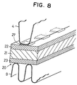
- a fourth preferred embodiment of the present invention will be described with reference to FIG. 8.
- a brazing member 27 made of aluminum alloy corresponding to "4047" is applied in stripes to a joint portion between the sacrifice anode layer 22 and each of the folds of each of the outer fins 4. Further, the inner fin 9 is inserted into each of the refrigerant passages 3 formed in each of the tubes 2, similarly to the third embodiment. According to the fourth embodiment, the same effect as in the second embodiment is obtained.
- a work-hardened aluminum alloy plate 30 is formed by uniformly rolling a two-layer aluminum alloy plate in a roller mill. As shown in FIG. 9A, the two-layer aluminum alloy plate has a core 31 and a sacrifice anode layer 32 clad on one side surface of the core 31. Materials of the core 31 and the sacrifice anode layer 32 may be respectively same as those of the core 21 and the sacrifice anode layer 23 in the first embodiment.
- the work-hardened aluminum alloy plate 30 is applied with heat treatment to have a distortion rate of about 10-20 %.
- the work-hardened aluminum alloy plate 30 is set in a pressing device and is cut to have a predetermined size.
- the work-hardened aluminum alloy plate 30 is formed into each of tubes 200 having a refrigerant passage 300 therein.
- the sacrifice anode layer 32 is disposed outside the tubes 200 to face air, and the core 31 is disposed inside the tubes 200 to face refrigerant.
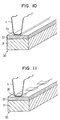
- each end of the work-hardened aluminum alloy plate 30 is applied with brazing material (not shown) corresponding to "4047". Each end of the work-hardened aluminum alloy plate 30 is brazed together by the brazing material to form each of the tubes 200. Further, as shown in FIG. 10, a brazing member 34 is applied in a straight line to a joint portion between the sacrifice anode layer 32 and each of folds of each of the outer fins 4.
- the brazing member 34 is made of Al-Si alloy corresponding to "4045" or "4104".
- a sixth preferred embodiment of the present invention will be described with reference to FIG. 11.
- a brazing member 35 is applied in stripes to a joint portion between the sacrifice anode layer 32 and each of the folds of each of the outer fins 4.
- the brazing member 35 is made of Al-Si alloy corresponding to "4045" or "4104".
- the brazing member 34 is applied in a straight line to a joint portion between the sacrifice anode layer 32 and each of the folds of each of the outer fins 4. Further, the inner fin 9 is inserted into each of the refrigerant passages 300 formed in each of the tubes 200 for improving efficiency of heat transfer between refrigerant and air. That is, the inner fin 9 is disposed on the core 31.
- the brazing member 35 is applied in stripes to a joint portion between the sacrifice anode layer 32 and each of the folds of each of the outer fins 4. Further, the inner fin 9 is inserted into each of the refrigerant passages 300 similarly to the seventh embodiment.
- an evaporator 100 has a laminated body 50 formed by laminating plural refrigerant passage members and side plates 51, 52. Each of the side plates 51, 52 is respectively connected to end surfaces of the laminated body 50.
- Each of the passage members is made by connecting a pair of thin core plates 40 made of aluminum alloy.
- Each of the core plates 40 has a recessed refrigerant passage 41 and a recessed refrigerant passage 42. The pair of the core plates 40 are connected so that the recessed passages 41, 42 are disposed inside each of the passage members.
- Refrigerant is introduced into the recessed passage 41 from an inlet pipe 53 formed on the side plate 51. Refrigerant flowing through the recessed passage 42 is discharged from an outlet pipe 54 formed on the side plate 51.
- a size of the recessed passage 42 is larger than that of the recessed passage 41 in a direction in which air passes through the evaporator 100. Heat exchange between refrigerant flowing through the recessed passages 41, 42 and air passing through the evaporator 100 is performed so that refrigerant is evaporated and air is cooled.
- Each of the core plates 40 has tank portions 43, 44 respectively formed at upper and lower ends of the recessed passage 41, and tank portions 45, 46 respectively formed at upper and lower ends of the recessed passage 42.
- Each of the tank portions 43-46 is an opening and communicates with a corresponding tank portion of adjacent passage members.
- ribs 47, 48 are respectively formed in the recessed passages 41, 42. That is, the ribs 47, 48 are disposed at a refrigerant side of each of the core plates 40.
- the ribs 47, 48 function as reinforcing members for improving pressure resistance of each of the core plates 40 and as inner fins for improving efficiency of heat transfer between air and refrigerant at the refrigerant side of each of the core plates 40, that is, inside the evaporator 100.
- the ribs 47, 48 function as outer fins for improving efficiency of heat transfer between air and refrigerant at an air side of each of the core plates 40, that is, outside the evaporator 100.
- each of the core plates 40 having the recessed passages 41, 42, the tank portions 43-46 and the ribs 47, 48 is integrally formed by shallow-drawing the work-hardened aluminum alloy plate 20 or 30 respectively according to the first or fifth embodiments.
- Each of the core plates 40 is formed so that the sacrifice anode layer 22 or 32 is disposed at the air side thereof, and the brazing layer 23 or the core 31 is disposed at the refrigerant side thereof.
- the plural core plates 40 are laminated to form the laminated body 50.
- the side plates 51, 52 are connected to the respective end of the laminated body 50 to form an assembled body.
- the assembled body is applied with flux powder so that the brazing layer 23 is uniformly wet, and is integrally brazed in a furnace. As a result, the evaporator 100 is formed.
- a corrugated outer fin having a height of 8-10 mm is disposed between adjacent passage members. Therefore, a tank portion of a core plate needs to be formed by deep-drawing to have a height of 4-5 mm.
- the laminated body 50 is formed by laminating only the core plates 40, and no outer fin is required to be disposed between adjacent passage members. Therefore, the tank portions 43-46 may be formed by shallow-drawing to have a height of 1 mm or the like.
- the evaporator 100 is formed only by shallow-drawing of the core plates 40. Therefore, a thickness of each of the core plates 40 can be decreased without causing crack, thereby reducing a size and a weight of the evaporator 100.
- the present invention is not limited to an evaporator, and may be applied to any other heat exchangers made of aluminum alloy such as a condenser or a supercooler for a vehicle air conditioner, or an oil cooler for an engine cooler.
- a heat exchanger for a refrigeration cycle such as a condenser or a supercooler
- refrigerant is used as non-corrosive fluid
- air is used as corrosive fluid, similarly to the evaporator 1.
- oil such as lubricant oil or operation oil is used as non-corrosive fluid and coolant or air is used as corrosive fluid.
Landscapes
- Engineering & Computer Science (AREA)
- Mechanical Engineering (AREA)
- Physics & Mathematics (AREA)
- Thermal Sciences (AREA)
- General Engineering & Computer Science (AREA)
- Heat-Exchange Devices With Radiators And Conduit Assemblies (AREA)
- Prevention Of Electric Corrosion (AREA)
Applications Claiming Priority (4)
| Application Number | Priority Date | Filing Date | Title |
|---|---|---|---|
| JP14924299 | 1999-05-28 | ||
| JP14924299 | 1999-05-28 | ||
| JP2000009956 | 2000-01-13 | ||
| JP2000009956A JP2001050690A (ja) | 1999-05-28 | 2000-01-13 | アルミニウム合金製熱交換器 |
Related Child Applications (1)
| Application Number | Title | Priority Date | Filing Date |
|---|---|---|---|
| EP06121351A Division EP1739484B1 (fr) | 2000-04-19 | 2001-04-18 | Plaque d'impression lithographique photosensible et procédé de fabrication d'une plaque d'impression |
Publications (1)
| Publication Number | Publication Date |
|---|---|
| EP1055898A2 true EP1055898A2 (fr) | 2000-11-29 |
Family
ID=26479176
Family Applications (1)
| Application Number | Title | Priority Date | Filing Date |
|---|---|---|---|
| EP00110962A Withdrawn EP1055898A2 (fr) | 1999-05-28 | 2000-05-26 | Echangeur de chaleur en alliage d'aluminium |
Country Status (4)
| Country | Link |
|---|---|
| US (1) | US20020078566A1 (fr) |
| EP (1) | EP1055898A2 (fr) |
| JP (1) | JP2001050690A (fr) |
| KR (1) | KR100355557B1 (fr) |
Cited By (5)
| Publication number | Priority date | Publication date | Assignee | Title |
|---|---|---|---|---|
| WO2003100337A2 (fr) * | 2002-05-28 | 2003-12-04 | Valeo Thermique Moteur | Dispositif de protection d'un echangeur de chaleur contre la corrosion |
| US6764558B2 (en) | 2000-11-16 | 2004-07-20 | Pechiney Rhenalu | Aluminum alloy strip manufacturing process for the manufacture of brazed heat exchangers |
| US6923876B2 (en) | 2000-11-16 | 2005-08-02 | Pechiney Rhenalu | Aluminum alloy strip manufacturing process for the manufacture of brazed heat exchangers |
| EP1558888A1 (fr) * | 2002-10-31 | 2005-08-03 | Oxycell Holding B.V. | Echangeur de chaleur et son procede de fabrication |
| CN103115504A (zh) * | 2013-02-20 | 2013-05-22 | 安徽天祥空调科技有限公司 | 汽车高效全铝换热器 |
Families Citing this family (14)
| Publication number | Priority date | Publication date | Assignee | Title |
|---|---|---|---|---|
| CN1325871C (zh) * | 2002-08-19 | 2007-07-11 | 乐金电子(天津)电器有限公司 | 防止冷冻机空调机用热交换机腐蚀的装置 |
| JP2005016937A (ja) * | 2003-06-06 | 2005-01-20 | Denso Corp | 耐食性に優れたアルミニウム製熱交換器 |
| JP4265509B2 (ja) * | 2003-12-03 | 2009-05-20 | 株式会社デンソー | 積層型冷却器 |
| DE102004057526B4 (de) * | 2003-12-03 | 2020-08-20 | Denso Corporation | Stapelkühler |
| DE102004059963A1 (de) | 2003-12-18 | 2005-08-11 | Denso Corp., Kariya | Einfach zusammengesetzter Kühler |
| JP2005203732A (ja) * | 2003-12-18 | 2005-07-28 | Denso Corp | 冷却器 |
| EP1836451B1 (fr) * | 2004-12-13 | 2017-11-08 | MAHLE Behr GmbH & Co. KG | Dispositif d'echange de chaleur destine a des gaz contenant de l'acide |
| DE102007005389A1 (de) * | 2007-02-03 | 2008-08-07 | Behr Gmbh & Co. Kg | Wärmeübertrager |
| JP5577616B2 (ja) * | 2009-04-06 | 2014-08-27 | 株式会社デンソー | 熱交換器用チューブ及び熱交換器 |
| US9482453B2 (en) | 2010-01-15 | 2016-11-01 | Ingersoll-Rand Company | Air dryer assembly |
| FR2967765B1 (fr) * | 2010-11-19 | 2015-03-06 | Valeo Systemes Thermiques | Composant brasable et echangeur de chaleur le comportant |
| CN103711570A (zh) * | 2013-12-27 | 2014-04-09 | 韦瑛 | 一种气流高顺畅性的中冷器管 |
| CN109070543B (zh) * | 2016-04-12 | 2021-09-07 | 格伦格斯有限公司 | 复合板产品的制造方法 |
| JP2018087660A (ja) * | 2016-11-29 | 2018-06-07 | 株式会社デンソー | ドロンカップ式熱交換器 |
Family Cites Families (3)
| Publication number | Priority date | Publication date | Assignee | Title |
|---|---|---|---|---|
| US6089708A (en) * | 1999-12-08 | 2000-07-18 | Ku; Kuo-Sheng | Eyeglasses frame having auxiliary eyeglasses |
| US6264323B1 (en) * | 2000-04-18 | 2001-07-24 | David Chao | Assembly of primary and auxiliary eyeglasses which are interconnected by a retainer clip |
| US6799846B1 (en) * | 2003-06-02 | 2004-10-05 | Sunshine Optical Company Limited | Connector for positioning a pair of sunglasses or sunlenses in front of a pair of eyeglasses |
-
2000
- 2000-01-13 JP JP2000009956A patent/JP2001050690A/ja active Pending
- 2000-05-26 EP EP00110962A patent/EP1055898A2/fr not_active Withdrawn
- 2000-05-26 KR KR1020000028755A patent/KR100355557B1/ko not_active IP Right Cessation
-
2001
- 2001-12-21 US US10/032,351 patent/US20020078566A1/en not_active Abandoned
Cited By (7)
| Publication number | Priority date | Publication date | Assignee | Title |
|---|---|---|---|---|
| US6764558B2 (en) | 2000-11-16 | 2004-07-20 | Pechiney Rhenalu | Aluminum alloy strip manufacturing process for the manufacture of brazed heat exchangers |
| US6923876B2 (en) | 2000-11-16 | 2005-08-02 | Pechiney Rhenalu | Aluminum alloy strip manufacturing process for the manufacture of brazed heat exchangers |
| WO2003100337A2 (fr) * | 2002-05-28 | 2003-12-04 | Valeo Thermique Moteur | Dispositif de protection d'un echangeur de chaleur contre la corrosion |
| FR2840396A1 (fr) * | 2002-05-28 | 2003-12-05 | Valeo Thermique Moteur Sa | Dispositif de protection d'un echangeur de chaleur contre la corrosion |
| WO2003100337A3 (fr) * | 2002-05-28 | 2004-04-01 | Valeo Thermique Moteur Sa | Dispositif de protection d'un echangeur de chaleur contre la corrosion |
| EP1558888A1 (fr) * | 2002-10-31 | 2005-08-03 | Oxycell Holding B.V. | Echangeur de chaleur et son procede de fabrication |
| CN103115504A (zh) * | 2013-02-20 | 2013-05-22 | 安徽天祥空调科技有限公司 | 汽车高效全铝换热器 |
Also Published As
| Publication number | Publication date |
|---|---|
| US20020078566A1 (en) | 2002-06-27 |
| KR100355557B1 (ko) | 2002-10-11 |
| JP2001050690A (ja) | 2001-02-23 |
| KR20000077466A (ko) | 2000-12-26 |
Similar Documents
| Publication | Publication Date | Title |
|---|---|---|
| EP1055898A2 (fr) | Echangeur de chaleur en alliage d'aluminium | |
| US7438121B2 (en) | Heat exchanger and method for manufacturing the same | |
| CN100425939C (zh) | 热交换器 | |
| US6513582B2 (en) | Heat exchanger and fluid pipe therefor | |
| CA2603028A1 (fr) | Refroidisseur d'air de suralimentation bimetallique resistant a la corrosion | |
| CA3018415A1 (fr) | Materiau composite d'aluminium dote d'une couche anticorrosion | |
| EP0867682A2 (fr) | Echangeur de chaleur en alliage d'aluminium | |
| EP1146311A1 (fr) | Procede de formation d'une couche de corrosion sacrificielle | |
| JP5963112B2 (ja) | ルームエアコン用アルミニウム製熱交換器 | |
| US12050067B2 (en) | Heat exchanger with aluminum alloy clad tube and method of manufacture | |
| US6361882B1 (en) | High-strength aluminum alloy clad material for heat exchangers exhibiting excellent corrosion resistance | |
| JP3753794B2 (ja) | 真空ろう付用アルミニウム材料及び該材料を用いた耐食性に優れたドロンカップ型熱交換器 | |
| AU2004207223A1 (en) | Heat exchanger and process for fabricating same | |
| JP3704178B2 (ja) | ろう付用アルミニウム材料及び該材料を用いた耐食性に優れたドロンカップ型熱交換器 | |
| JP3929854B2 (ja) | 熱交換器用押出扁平チューブ並びにそれを使用した熱交換器 | |
| JP2691069B2 (ja) | 耐食性及び伝熱性にすぐれた熱交換器 | |
| US20060151155A1 (en) | Heat exchanger and process for fabricating same | |
| JP3850082B2 (ja) | アルミニウム合金製熱交換器 | |
| US20060185168A1 (en) | Aluminum pipe and process for producing same | |
| JP2000135591A (ja) | 耐食性に優れた熱交換器用アルミニウム合金クラッド材 | |
| TWI304445B (en) | Alumunum pipe and process for producing same | |
| JP2768393B2 (ja) | ろう付け後の強度および犠牲陽極効果にすぐれた熱交換器フィン材用アルミニウム合金 | |
| Fortin et al. | Aluminum materials and processes for automotive heat exchanger applications | |
| JP2002018588A (ja) | 耐食性に優れた熱交換器用アルミニウム合金クラッド材 | |
| JPH10288495A (ja) | 熱交換器用アルミニウム合金フィン材 |
Legal Events
| Date | Code | Title | Description |
|---|---|---|---|
| PUAI | Public reference made under article 153(3) epc to a published international application that has entered the european phase |
Free format text: ORIGINAL CODE: 0009012 |
|
| AK | Designated contracting states |
Kind code of ref document: A2 Designated state(s): AT BE CH CY DE DK ES FI FR GB GR IE IT LI LU MC NL PT SE |
|
| AX | Request for extension of the european patent |
Free format text: AL;LT;LV;MK;RO;SI |
|
| STAA | Information on the status of an ep patent application or granted ep patent |
Free format text: STATUS: THE APPLICATION IS DEEMED TO BE WITHDRAWN |
|
| 18D | Application deemed to be withdrawn |
Effective date: 20041201 |