EP1053388B1 - Soupape legere - Google Patents
Soupape legere Download PDFInfo
- Publication number
- EP1053388B1 EP1053388B1 EP99908830A EP99908830A EP1053388B1 EP 1053388 B1 EP1053388 B1 EP 1053388B1 EP 99908830 A EP99908830 A EP 99908830A EP 99908830 A EP99908830 A EP 99908830A EP 1053388 B1 EP1053388 B1 EP 1053388B1
- Authority
- EP
- European Patent Office
- Prior art keywords
- valve
- shaft
- cone
- disk
- lightweight
- Prior art date
- Legal status (The legal status is an assumption and is not a legal conclusion. Google has not performed a legal analysis and makes no representation as to the accuracy of the status listed.)
- Expired - Lifetime
Links
Images

Classifications
-
- F—MECHANICAL ENGINEERING; LIGHTING; HEATING; WEAPONS; BLASTING
- F01—MACHINES OR ENGINES IN GENERAL; ENGINE PLANTS IN GENERAL; STEAM ENGINES
- F01L—CYCLICALLY OPERATING VALVES FOR MACHINES OR ENGINES
- F01L3/00—Lift-valve, i.e. cut-off apparatus with closure members having at least a component of their opening and closing motion perpendicular to the closing faces; Parts or accessories thereof
- F01L3/12—Cooling of valves
-
- F—MECHANICAL ENGINEERING; LIGHTING; HEATING; WEAPONS; BLASTING
- F01—MACHINES OR ENGINES IN GENERAL; ENGINE PLANTS IN GENERAL; STEAM ENGINES
- F01L—CYCLICALLY OPERATING VALVES FOR MACHINES OR ENGINES
- F01L3/00—Lift-valve, i.e. cut-off apparatus with closure members having at least a component of their opening and closing motion perpendicular to the closing faces; Parts or accessories thereof
- F01L3/02—Selecting particular materials for valve-members or valve-seats; Valve-members or valve-seats composed of two or more materials
- F01L3/04—Coated valve members or valve-seats
-
- F—MECHANICAL ENGINEERING; LIGHTING; HEATING; WEAPONS; BLASTING
- F01—MACHINES OR ENGINES IN GENERAL; ENGINE PLANTS IN GENERAL; STEAM ENGINES
- F01L—CYCLICALLY OPERATING VALVES FOR MACHINES OR ENGINES
- F01L3/00—Lift-valve, i.e. cut-off apparatus with closure members having at least a component of their opening and closing motion perpendicular to the closing faces; Parts or accessories thereof
- F01L3/20—Shapes or constructions of valve members, not provided for in preceding subgroups of this group
-
- Y—GENERAL TAGGING OF NEW TECHNOLOGICAL DEVELOPMENTS; GENERAL TAGGING OF CROSS-SECTIONAL TECHNOLOGIES SPANNING OVER SEVERAL SECTIONS OF THE IPC; TECHNICAL SUBJECTS COVERED BY FORMER USPC CROSS-REFERENCE ART COLLECTIONS [XRACs] AND DIGESTS
- Y10—TECHNICAL SUBJECTS COVERED BY FORMER USPC
- Y10T—TECHNICAL SUBJECTS COVERED BY FORMER US CLASSIFICATION
- Y10T29/00—Metal working
- Y10T29/49—Method of mechanical manufacture
- Y10T29/49229—Prime mover or fluid pump making
- Y10T29/49298—Poppet or I.C. engine valve or valve seat making
- Y10T29/49307—Composite or hollow valve stem or head making
Definitions
- the invention relates to a lightweight valve, in particular for an internal combustion engine according to the preamble of Claim 1.
- valve is known from US-A-1 506 900 or DE 36 25 590 A.
- the valve disclosed in DE-A-3 625 590 is said to contribute to development an engine type with heat-insulated combustion chambers represent.
- the one facing the combustion chamber Valve plate is particularly thin-walled. This measure should a low heat absorption of the valve plate and cause correspondingly low heat losses.
- About the thin walls of the valve plate are to be extended of the valve stem additional components as a support provided between the valve plate and valve stem.
- Lightweight valves are also known for. B. from the DE 1 960 331 A, EP 0 091 097 A, US 2,731,708 or U.S. 1,294,416.
- valve Cavity to create a relatively large, unsupported Floor area formed towards the combustion chamber, which in operation - especially with minimized wall thicknesses - due to the combustion pressure is deformed.
- the through these deformations resulting displacements on the peripheral surface of the Valve seat contribute to premature wear of the Seat and additional stress on the valve.
- these deformations cause additional stress in the area of the joint between the valve plate and valve cone with the risk of the connection bursting open.
- a support of the valve plate is in itself from the US 2,439,240 known.
- the solution presented there is due to the design of the support in terms of manufacturing technology consuming.
- valve disc is also supported against the stem known from DE 36 25 590 A.
- a disadvantage of those disclosed there Solutions is, however, that the support with the help an additional adapter between the valve disc and shaft is fixed, and that the wall thickness of the valve plate is very low, so that deformation of the Valve head are to be expected.
- the invention is therefore concerned with the problem of a lightweight valve the rigidity in a simple way to increase the valve head and manufacture the To facilitate the valve.
- Deformation values can be achieved with valves according to the invention realize that in the range of values of valves with a Valve head made of solid material.
- the mass reduction this lightweight valve is at least 40% in comparison with solid steel valves.
- the embodiment according to claim 1 represents an extensive Change from the usual design for lightweight valves because the valve cone is no longer integral with the Valve stem, but is manufactured as a single part and the valve stem itself - possibly with an enlarged diameter - continues to the valve plate.
- the shaft is preferably drawn or welded Pipe made or made of solid material.
- the valve cone is preferably fixed to the stem by soldering or welding.
- 'Radially inside' means: away from the outside diameter of the valve plate.
- the valve according to the invention becomes a lightweight valve created that even with thin walls and accordingly low weight and high rigidity.
- the invention is based on the basic idea that on the Valve plate acting gas forces through direct support of the valve plate against the stem.
- the valve disc is supported against the valve stem in connection with the valve cone a rigid Rotational surface structure with an approximately triangular cross-section.
- a lightweight valve is known from US 4,834,036 which the shaft extends into the area of the valve plate, however, the valve head is a light, cast or forged solid material Titanium base like titanium aluminide, so this valve is generic does not belong to the hollow valves according to the invention.
- a valve from US 1,506,900 is also still out known in 1924, which has a similar structure, from which the invention differs, however, by a different one Wall thickness ratio and another training regarding the connection of the shaft end to the valve disk different.
- the relatively thin one disclosed there Wall thickness of the valve disc compared to the valve cone is unfavorable in terms of strength, as is the breakthrough in Valve plate for receiving the valve stem end.
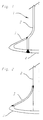
- a valve 1 for an internal combustion engine consists of a Shaft 2, a valve base, not shown, a funnel-shaped Valve plug 3 and one piece with the valve plug manufactured valve disc 4.
- the diameter of the Shaft is expanded at the level of valve cone 3.
- On his the lower end is the stem 2 with the valve plate 4 welded.
- the valve cone 3 is at its upper end welded to the shaft 2.
- the valve cone 3, the valve disk 4 and the lower, connecting both, expanded Shaft ends together form a rigid rotational surface structure.
- the wall thickness of the valve cone 3 is smaller than the wall thickness of the valve plate 4.
- valve plates 4 and valve cone 3 not in one piece, but by one Weld seam joined together.
- the shaft is there made of solid material.
- the shaft can be below the Weld also have a smaller diameter than in the area above the weld.
- valve plate 4 and valve cone 3 are in one piece and in the valve plate 4 is a centering for the end of Shaft 2 provided.
- a welded joint is only between the upper end of the valve plug 3 and the stem intended.
- the wall thickness of the valve plate 4 greater than the wall thickness of the valve plug 3.
- Fig. 4 is a valve plate 4 with a molded collar-shaped support according to claim 5 shown.
Landscapes
- Engineering & Computer Science (AREA)
- Mechanical Engineering (AREA)
- General Engineering & Computer Science (AREA)
- Physics & Mathematics (AREA)
- Geometry (AREA)
- Valve-Gear Or Valve Arrangements (AREA)
Claims (6)
- Soupape légère, en particulier pour un moteur à combustion interne, comprenant une tige, un cône de soupape et une tête de soupape, le cône de soupape et la tête de soupape formant conjointement un espace creux et les épaisseurs de parois de la tête et du cône de soupape présentant par rapport au diamètre de la tige un rapport inférieur à 1 : 3, avec les caractéristiquesa) la tête de soupape (4) s'appuie contre la tige de soupape (2) dans une zone radiale interne,b) le cône de soupape (3) et la tige de soupape (2) se composent de deux composants différents assemblés entre eux, ne sont donc pas monobloc,c) le cône de soupape (3) est fixé sur son extrémité supérieure sur la tige de soupape (2),
caractérisée par les caractéristiquesd) l'extrémité de la tige de soupape (2) se situe directement - sans pièce intermédiaire - sur la tête de soupape ou sur un collet monobloc avec la tête de soupape, ou la tige de soupape (2) est monobloc avec la tête de soupape (4),e) le rapport des épaisseurs de parois entre le cône de soupape (3) et la tête de soupape (4) est inférieur à 0,7,f) la tête de soupape (4) ne présente aucune percée pour recevoir l'extrémité de la tige de soupape. - Soupape légère suivant la revendication 1, caractérisée en ce que la tige (2) est fixée sur la tête de soupape (4).
- Soupape légère suivant l'une des revendications précédentes, caractérisée en ce que la tige (2) présente au niveau du cône de soupape (3) un diamètre supérieur au diamètre situé dans une zone sus-jacente au cône de soupape (3).
- Soupape légère suivant la revendication 3, caractérisée en ce que la transition en direction du diamètre de tige supérieur est conformée en cône de sorte qu' il en résulte à l'état de soudage une fermeture de niveau avec le cône de soupape (3).
- Soupape légère suivant la revendication 1, caractérisée en ce qu'un support est conformé sur la tête de soupape (4) d'une seule pièce avec cette dernière, support par lequel la tête de soupape (4) s'appuie contre la tige de soupape (2).
- Soupape légère suivant l'une des revendications précédentes, caractérisée en ce que le cône de soupape (3) et la tête de soupape (4) sont monobloc.
Priority Applications (1)
| Application Number | Priority Date | Filing Date | Title |
|---|---|---|---|
| EP03014001A EP1359292A1 (fr) | 1998-02-03 | 1999-01-28 | Soupape allégée |
Applications Claiming Priority (3)
| Application Number | Priority Date | Filing Date | Title |
|---|---|---|---|
| DE19804053A DE19804053A1 (de) | 1998-02-03 | 1998-02-03 | Leichtbauventil |
| DE19804053 | 1998-02-03 | ||
| PCT/EP1999/000561 WO1999040295A1 (fr) | 1998-02-03 | 1999-01-28 | Soupape legere |
Related Child Applications (1)
| Application Number | Title | Priority Date | Filing Date |
|---|---|---|---|
| EP03014001.6 Division-Into | 2003-06-21 |
Publications (2)
| Publication Number | Publication Date |
|---|---|
| EP1053388A1 EP1053388A1 (fr) | 2000-11-22 |
| EP1053388B1 true EP1053388B1 (fr) | 2003-12-10 |
Family
ID=7856414
Family Applications (2)
| Application Number | Title | Priority Date | Filing Date |
|---|---|---|---|
| EP99908830A Expired - Lifetime EP1053388B1 (fr) | 1998-02-03 | 1999-01-28 | Soupape legere |
| EP03014001A Withdrawn EP1359292A1 (fr) | 1998-02-03 | 1999-01-28 | Soupape allégée |
Family Applications After (1)
| Application Number | Title | Priority Date | Filing Date |
|---|---|---|---|
| EP03014001A Withdrawn EP1359292A1 (fr) | 1998-02-03 | 1999-01-28 | Soupape allégée |
Country Status (7)
| Country | Link |
|---|---|
| US (1) | US6354258B1 (fr) |
| EP (2) | EP1053388B1 (fr) |
| JP (1) | JP4282900B2 (fr) |
| AR (1) | AR018055A1 (fr) |
| BR (1) | BR9908554A (fr) |
| DE (2) | DE19804053A1 (fr) |
| WO (1) | WO1999040295A1 (fr) |
Cited By (2)
| Publication number | Priority date | Publication date | Assignee | Title |
|---|---|---|---|---|
| DE102013216188A1 (de) * | 2013-08-14 | 2015-03-12 | Mahle International Gmbh | Leichtmetalleinlassventil |
| DE102006061127B4 (de) * | 2006-12-22 | 2016-07-14 | Mahle International Gmbh | Metallisches Leichtbauventil eines Verbrennungsmotors |
Families Citing this family (24)
| Publication number | Priority date | Publication date | Assignee | Title |
|---|---|---|---|---|
| DE50000201D1 (de) * | 2000-09-29 | 2002-07-11 | Ford Global Tech Inc | Ventil für Brennkraftmaschinen |
| DE10256274A1 (de) * | 2001-12-27 | 2003-07-17 | Mahle Ventiltrieb Gmbh | Verfahren zur Herstellung eines Gaswechselventils eines Verbrennungsmotors |
| DE10209770A1 (de) * | 2002-03-05 | 2003-10-09 | Daimler Chrysler Ag | Leichtbauventil |
| DE10217719A1 (de) * | 2002-04-20 | 2003-11-06 | Mahle Ventiltrieb Gmbh | Beweglicher, heißen Gasen ausgesetzter Verschlusskörper eines Ventiles |
| DE10354077B4 (de) | 2003-11-19 | 2005-10-20 | Daimler Chrysler Ag | Leichtbauventil |
| DE10354074B4 (de) * | 2003-11-19 | 2006-01-26 | Daimlerchrysler Ag | Leichtbauventil |
| DE10354085B4 (de) | 2003-11-19 | 2005-11-24 | Daimlerchrysler Ag | Leichtbauventil |
| DE10354076B4 (de) * | 2003-11-19 | 2006-03-09 | Daimlerchrysler Ag | Leichtbauventil |
| DE10354086B4 (de) | 2003-11-19 | 2005-11-24 | Daimlerchrysler Ag | Leichtbauventil |
| US7240895B2 (en) | 2004-03-03 | 2007-07-10 | Mahle Ventiltrieb Gmbh | Gas exchange valve for an internal combustion engine |
| DE102004010309A1 (de) * | 2004-03-03 | 2005-09-22 | Mahle Ventiltrieb Gmbh | Gaswechselventil eines Verbrennungsmotors |
| US20060118177A1 (en) * | 2004-12-07 | 2006-06-08 | Ucman Robert C | Coated valve and method of making same |
| DE102005005041A1 (de) * | 2005-02-03 | 2006-08-10 | Märkisches Werk GmbH | Ventil zur Steuerung des Gasaustauschs, insbesondere bei Verbrennungsmotoren |
| DE102005027130A1 (de) * | 2005-06-11 | 2006-12-14 | Mahle International Gmbh | Gaswechselventil eines Verbrennungsmotors |
| DE102006049844A1 (de) * | 2006-10-20 | 2008-04-24 | Gkss-Forschungszentrum Geesthacht Gmbh | Verfahren zur Herstellung von Bauteilen für Verbrennungsmotoren oder Turbinen |
| DE102006061128B4 (de) * | 2006-12-22 | 2015-06-11 | Mahle International Gmbh | Gaswechselventil eines Verbrennungsmotors |
| DE102010051871A1 (de) | 2010-11-22 | 2012-05-24 | Märkisches Werk GmbH | Verfahren zur Herstellung von Ventilen für den Gasaustausch und nach einem derartigen Verfahren hergestellte Ventile |
| DE102012209187A1 (de) | 2011-06-08 | 2012-12-13 | Mahle International Gmbh | Verfahren zum Herstellen eines metallischen Hohlventils mit verbesserter Kühlung |
| DE102011077198A1 (de) | 2011-06-08 | 2012-12-13 | Mahle International Gmbh | Verfahren zum Herstellen eines metallischen Hohlventils mit verbesserter Kühlung |
| DE102013203443A1 (de) * | 2013-02-28 | 2014-08-28 | Mahle International Gmbh | Metallisches Hohlventil |
| DE102013203441A1 (de) | 2013-02-28 | 2014-08-28 | Bayerische Motoren Werke Aktiengesellschaft | Betriebsverfahren für ein einachsiges Wankstabilisierungssystem eines zweiachsigen, zweispurigen Fahrzeugs |
| DE102013210899A1 (de) | 2013-06-11 | 2014-12-11 | Mahle International Gmbh | Verfahren zur Herstellung eines gebauten Hohlventils |
| DE102013210900A1 (de) * | 2013-06-11 | 2014-12-11 | Mahle International Gmbh | Gaswechselventil einer Brennkraftmaschine |
| JP6653050B1 (ja) * | 2018-03-20 | 2020-02-26 | 日鍛バルブ株式会社 | 排気用中空ポペットバルブ |
Family Cites Families (19)
| Publication number | Priority date | Publication date | Assignee | Title |
|---|---|---|---|---|
| US2734008A (en) * | 1956-02-07 | Method of making heat treating and hardening valves | ||
| US1294416A (en) | 1918-01-02 | 1919-02-18 | Pfanstiehl Company Inc | Valve and method of making the same. |
| US1506900A (en) * | 1922-06-29 | 1924-09-02 | Greiner Adolph | Valve |
| US1557022A (en) * | 1922-11-03 | 1925-10-13 | Aeromarine Plane & Motor Compa | Valve and method of making same |
| US1727621A (en) * | 1928-02-18 | 1929-09-10 | Gen Motors Corp | Exhaust valve |
| DE762642C (de) * | 1942-08-21 | 1954-08-02 | Daimler Benz Ag | Auslassventil fuer Brennkraftmaschinen, insbesondere Flugmotoren |
| US2371548A (en) | 1943-12-06 | 1945-03-13 | Thomas F Saffady | Valve |
| US2398514A (en) | 1944-10-14 | 1946-04-16 | Wilhelm B Bronander | Internal-combustion engine |
| US2439240A (en) | 1945-01-18 | 1948-04-06 | Thompson Prod Inc | Braced head dome valve |
| DE910492C (de) * | 1951-10-03 | 1954-05-03 | Wilhelm Schmidt | Hohles Tellerventil |
| US2731708A (en) | 1952-10-31 | 1956-01-24 | Teves Kg Alfred | Process for manufacture of hollow poppet valves especially for internal-combustion engines |
| DE1960331A1 (de) | 1969-12-02 | 1971-06-03 | Porsche Kg | Kegelventil,insbesondere fuer Brennkraftmaschinen |
| JPS58151306U (ja) | 1982-04-05 | 1983-10-11 | 日産自動車株式会社 | 内燃機関の吸排気バルブ |
| DE3233392A1 (de) * | 1982-08-31 | 1984-03-01 | Gebrüder Sulzer AG, 8401 Winterthur | Tellerventil fuer ein gaswechselventil |
| JPS60169611A (ja) | 1984-02-14 | 1985-09-03 | Mitsubishi Heavy Ind Ltd | 内燃機関の排気弁 |
| DE3625590A1 (de) * | 1986-07-29 | 1988-02-04 | Odilo Schwaiger | Ventile fuer brennkraftmaschinen |
| DE3625560A1 (de) | 1986-07-29 | 1988-02-04 | Siemens Ag | Gaslaser |
| JPS643007U (fr) | 1987-06-25 | 1989-01-10 | ||
| US5771852A (en) | 1997-03-04 | 1998-06-30 | Trw Inc. | Poppet valve with embossed neck structure |
-
1998
- 1998-02-03 DE DE19804053A patent/DE19804053A1/de not_active Ceased
-
1999
- 1999-01-28 EP EP99908830A patent/EP1053388B1/fr not_active Expired - Lifetime
- 1999-01-28 US US09/601,497 patent/US6354258B1/en not_active Expired - Fee Related
- 1999-01-28 BR BR9908554-2A patent/BR9908554A/pt not_active IP Right Cessation
- 1999-01-28 DE DE59908022T patent/DE59908022D1/de not_active Expired - Lifetime
- 1999-01-28 EP EP03014001A patent/EP1359292A1/fr not_active Withdrawn
- 1999-01-28 JP JP2000530689A patent/JP4282900B2/ja not_active Expired - Fee Related
- 1999-01-28 WO PCT/EP1999/000561 patent/WO1999040295A1/fr active IP Right Grant
- 1999-02-03 AR ARP990100450A patent/AR018055A1/es unknown
Cited By (2)
| Publication number | Priority date | Publication date | Assignee | Title |
|---|---|---|---|---|
| DE102006061127B4 (de) * | 2006-12-22 | 2016-07-14 | Mahle International Gmbh | Metallisches Leichtbauventil eines Verbrennungsmotors |
| DE102013216188A1 (de) * | 2013-08-14 | 2015-03-12 | Mahle International Gmbh | Leichtmetalleinlassventil |
Also Published As
| Publication number | Publication date |
|---|---|
| WO1999040295A1 (fr) | 1999-08-12 |
| JP4282900B2 (ja) | 2009-06-24 |
| EP1359292A1 (fr) | 2003-11-05 |
| JP2002502928A (ja) | 2002-01-29 |
| AR018055A1 (es) | 2001-10-31 |
| EP1053388A1 (fr) | 2000-11-22 |
| DE19804053A1 (de) | 1999-08-05 |
| DE59908022D1 (de) | 2004-01-22 |
| US6354258B1 (en) | 2002-03-12 |
| BR9908554A (pt) | 2001-10-30 |
Similar Documents
| Publication | Publication Date | Title |
|---|---|---|
| EP1053388B1 (fr) | Soupape legere | |
| EP2089611B1 (fr) | Turbocompresseur et procédé de fabrication correspondant | |
| EP0265663B1 (fr) | Méthode de fabrication d'un arbre à cames ainsi qu'arbre à cames fabriqué d'un tube et d'éléments mis sur ce tube | |
| DE102005034306A1 (de) | Verfahren zur Herstellung eines Kolbens einer Brennkraftmaschine zur Bildung einer Bewehrung einer Brennraummulde des Kolbens | |
| EP2162613B1 (fr) | Piston pour moteur à combustion interne, présentant des parois à obliquité accrue | |
| EP1502011B1 (fr) | Came monobloc, son procede de fabrication, et assemblage d'un arbre de commande ou arbre a came | |
| EP0271638B1 (fr) | Arbre coulé, en particulier arbres à cames | |
| DE69506386T2 (de) | Achse für zweiteiligen kolben | |
| EP1722114A2 (fr) | Bielle solide et légère | |
| EP1454037A1 (fr) | Soupape en plusieurs parties pour moteurs a piston alternatif | |
| WO2008122653A1 (fr) | Came pour un arbre à cames ou arbre de commande | |
| DE3737600A1 (de) | Verfahren zur herstellung von aufgebauten kurbelwellen durch aufweiten von in geteilten zapfen angeordneten huelsen | |
| WO2007025733A1 (fr) | Geometrie d'alesage d'axe de piston continue destinee a un piston d'un moteur a combustion interne | |
| DE10354086B4 (de) | Leichtbauventil | |
| DE3733910C2 (fr) | ||
| EP1419001B1 (fr) | Boitier | |
| AT5130U1 (de) | Stösselstange, insbesondere für eine ventilbetätigungseinrichtung einer brennkraftmaschine | |
| WO1999028638A1 (fr) | Bielle motrice pour moteur alternatif a combustion interne, ainsi que procede de fabrication de ladite bielle | |
| DE102005061060A1 (de) | Kolben für einen Verbrennungsmotor und Verfahren zu seiner Herstellung | |
| DE102014106470B4 (de) | Lagerbuchse für ein Fahrwerks- oder Getriebebauteil eines Kraftfahrzeuges | |
| EP0326606A1 (fr) | Vilebrequin compose et son procede de fabrication | |
| DE3233906A1 (de) | Nockenwelle | |
| DE10354076B4 (de) | Leichtbauventil | |
| DE8626272U1 (de) | Gebaute Nockenwelle aus einem Wellenrohr und aufgeschobenen Elementen | |
| DE102006061127B4 (de) | Metallisches Leichtbauventil eines Verbrennungsmotors |
Legal Events
| Date | Code | Title | Description |
|---|---|---|---|
| PUAI | Public reference made under article 153(3) epc to a published international application that has entered the european phase |
Free format text: ORIGINAL CODE: 0009012 |
|
| 17P | Request for examination filed |
Effective date: 20000706 |
|
| AK | Designated contracting states |
Kind code of ref document: A1 Designated state(s): CH DE FR GB IT LI |
|
| 17Q | First examination report despatched |
Effective date: 20030204 |
|
| GRAP | Despatch of communication of intention to grant a patent |
Free format text: ORIGINAL CODE: EPIDOSNIGR1 |
|
| GRAS | Grant fee paid |
Free format text: ORIGINAL CODE: EPIDOSNIGR3 |
|
| GRAA | (expected) grant |
Free format text: ORIGINAL CODE: 0009210 |
|
| AK | Designated contracting states |
Kind code of ref document: B1 Designated state(s): CH DE FR GB IT LI |
|
| REG | Reference to a national code |
Ref country code: GB Ref legal event code: FG4D Free format text: NOT ENGLISH |
|
| REG | Reference to a national code |
Ref country code: CH Ref legal event code: EP |
|
| REF | Corresponds to: |
Ref document number: 59908022 Country of ref document: DE Date of ref document: 20040122 Kind code of ref document: P |
|
| PG25 | Lapsed in a contracting state [announced via postgrant information from national office to epo] |
Ref country code: LI Free format text: LAPSE BECAUSE OF NON-PAYMENT OF DUE FEES Effective date: 20040131 Ref country code: CH Free format text: LAPSE BECAUSE OF NON-PAYMENT OF DUE FEES Effective date: 20040131 |
|
| GBT | Gb: translation of ep patent filed (gb section 77(6)(a)/1977) |
Effective date: 20040118 |
|
| REG | Reference to a national code |
Ref country code: CH Ref legal event code: PL |
|
| ET | Fr: translation filed | ||
| PLBE | No opposition filed within time limit |
Free format text: ORIGINAL CODE: 0009261 |
|
| STAA | Information on the status of an ep patent application or granted ep patent |
Free format text: STATUS: NO OPPOSITION FILED WITHIN TIME LIMIT |
|
| 26N | No opposition filed |
Effective date: 20040913 |
|
| REG | Reference to a national code |
Ref country code: FR Ref legal event code: PLFP Year of fee payment: 18 |
|
| REG | Reference to a national code |
Ref country code: FR Ref legal event code: PLFP Year of fee payment: 19 |
|
| PGFP | Annual fee paid to national office [announced via postgrant information from national office to epo] |
Ref country code: FR Payment date: 20170126 Year of fee payment: 19 |
|
| PGFP | Annual fee paid to national office [announced via postgrant information from national office to epo] |
Ref country code: GB Payment date: 20170131 Year of fee payment: 19 |
|
| PGFP | Annual fee paid to national office [announced via postgrant information from national office to epo] |
Ref country code: IT Payment date: 20170123 Year of fee payment: 19 |
|
| PGFP | Annual fee paid to national office [announced via postgrant information from national office to epo] |
Ref country code: DE Payment date: 20170331 Year of fee payment: 19 |
|
| REG | Reference to a national code |
Ref country code: DE Ref legal event code: R084 Ref document number: 59908022 Country of ref document: DE |
|
| REG | Reference to a national code |
Ref country code: DE Ref legal event code: R119 Ref document number: 59908022 Country of ref document: DE |
|
| GBPC | Gb: european patent ceased through non-payment of renewal fee |
Effective date: 20180128 |
|
| PG25 | Lapsed in a contracting state [announced via postgrant information from national office to epo] |
Ref country code: FR Free format text: LAPSE BECAUSE OF NON-PAYMENT OF DUE FEES Effective date: 20180131 Ref country code: DE Free format text: LAPSE BECAUSE OF NON-PAYMENT OF DUE FEES Effective date: 20180801 |
|
| REG | Reference to a national code |
Ref country code: FR Ref legal event code: ST Effective date: 20180928 |
|
| PG25 | Lapsed in a contracting state [announced via postgrant information from national office to epo] |
Ref country code: GB Free format text: LAPSE BECAUSE OF NON-PAYMENT OF DUE FEES Effective date: 20180128 |
|
| PG25 | Lapsed in a contracting state [announced via postgrant information from national office to epo] |
Ref country code: IT Free format text: LAPSE BECAUSE OF NON-PAYMENT OF DUE FEES Effective date: 20180128 |