EP2089611B1 - Turbocompresseur et procédé de fabrication correspondant - Google Patents
Turbocompresseur et procédé de fabrication correspondant Download PDFInfo
- Publication number
- EP2089611B1 EP2089611B1 EP07856267.5A EP07856267A EP2089611B1 EP 2089611 B1 EP2089611 B1 EP 2089611B1 EP 07856267 A EP07856267 A EP 07856267A EP 2089611 B1 EP2089611 B1 EP 2089611B1
- Authority
- EP
- European Patent Office
- Prior art keywords
- bore
- rotor shaft
- journal
- embodied
- turbine
- Prior art date
- Legal status (The legal status is an assumption and is not a legal conclusion. Google has not performed a legal analysis and makes no representation as to the accuracy of the status listed.)
- Not-in-force
Links
Images


Classifications
-
- F—MECHANICAL ENGINEERING; LIGHTING; HEATING; WEAPONS; BLASTING
- F02—COMBUSTION ENGINES; HOT-GAS OR COMBUSTION-PRODUCT ENGINE PLANTS
- F02B—INTERNAL-COMBUSTION PISTON ENGINES; COMBUSTION ENGINES IN GENERAL
- F02B39/00—Component parts, details, or accessories relating to, driven charging or scavenging pumps, not provided for in groups F02B33/00 - F02B37/00
-
- F—MECHANICAL ENGINEERING; LIGHTING; HEATING; WEAPONS; BLASTING
- F01—MACHINES OR ENGINES IN GENERAL; ENGINE PLANTS IN GENERAL; STEAM ENGINES
- F01D—NON-POSITIVE DISPLACEMENT MACHINES OR ENGINES, e.g. STEAM TURBINES
- F01D5/00—Blades; Blade-carrying members; Heating, heat-insulating, cooling or antivibration means on the blades or the members
- F01D5/02—Blade-carrying members, e.g. rotors
- F01D5/025—Fixing blade carrying members on shafts
-
- F—MECHANICAL ENGINEERING; LIGHTING; HEATING; WEAPONS; BLASTING
- F01—MACHINES OR ENGINES IN GENERAL; ENGINE PLANTS IN GENERAL; STEAM ENGINES
- F01D—NON-POSITIVE DISPLACEMENT MACHINES OR ENGINES, e.g. STEAM TURBINES
- F01D5/00—Blades; Blade-carrying members; Heating, heat-insulating, cooling or antivibration means on the blades or the members
- F01D5/02—Blade-carrying members, e.g. rotors
-
- F—MECHANICAL ENGINEERING; LIGHTING; HEATING; WEAPONS; BLASTING
- F02—COMBUSTION ENGINES; HOT-GAS OR COMBUSTION-PRODUCT ENGINE PLANTS
- F02C—GAS-TURBINE PLANTS; AIR INTAKES FOR JET-PROPULSION PLANTS; CONTROLLING FUEL SUPPLY IN AIR-BREATHING JET-PROPULSION PLANTS
- F02C6/00—Plural gas-turbine plants; Combinations of gas-turbine plants with other apparatus; Adaptations of gas- turbine plants for special use
- F02C6/04—Gas-turbine plants providing heated or pressurised working fluid for other apparatus, e.g. without mechanical power output
- F02C6/10—Gas-turbine plants providing heated or pressurised working fluid for other apparatus, e.g. without mechanical power output supplying working fluid to a user, e.g. a chemical process, which returns working fluid to a turbine of the plant
- F02C6/12—Turbochargers, i.e. plants for augmenting mechanical power output of internal-combustion piston engines by increase of charge pressure
-
- F—MECHANICAL ENGINEERING; LIGHTING; HEATING; WEAPONS; BLASTING
- F05—INDEXING SCHEMES RELATING TO ENGINES OR PUMPS IN VARIOUS SUBCLASSES OF CLASSES F01-F04
- F05D—INDEXING SCHEME FOR ASPECTS RELATING TO NON-POSITIVE-DISPLACEMENT MACHINES OR ENGINES, GAS-TURBINES OR JET-PROPULSION PLANTS
- F05D2220/00—Application
- F05D2220/40—Application in turbochargers
-
- Y—GENERAL TAGGING OF NEW TECHNOLOGICAL DEVELOPMENTS; GENERAL TAGGING OF CROSS-SECTIONAL TECHNOLOGIES SPANNING OVER SEVERAL SECTIONS OF THE IPC; TECHNICAL SUBJECTS COVERED BY FORMER USPC CROSS-REFERENCE ART COLLECTIONS [XRACs] AND DIGESTS
- Y10—TECHNICAL SUBJECTS COVERED BY FORMER USPC
- Y10T—TECHNICAL SUBJECTS COVERED BY FORMER US CLASSIFICATION
- Y10T29/00—Metal working
- Y10T29/49—Method of mechanical manufacture
- Y10T29/49316—Impeller making
- Y10T29/4932—Turbomachine making
- Y10T29/49321—Assembling individual fluid flow interacting members, e.g., blades, vanes, buckets, on rotary support member
Definitions
- the invention relates to a turbocharger according to the preamble of claim 1, and to a method for producing such a turbine rotor according to claim 6.
- a generic turbocharger is from the EP 1 621 774 A2 and the US 5 339 521 A known.
- this object is achieved by the features of claim 1.
- the object is achieved by the features of claim 6.
- the axes of the turbine wheel and the rotor shaft align well with each other and the heat conduction from the turbine wheel to the rotor shaft to diminish.
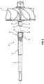
- Fig. 1 an inventive turbocharger 1 is illustrated in a partially broken view.
- the turbocharger 1 has a turbine 2, which comprises an exhaust gas inlet opening 3 and an exhaust gas outlet opening 4.
- a turbine wheel 5 is disposed in the turbine housing of the turbine 2, which is fixed to one end of a rotor shaft 6.
- a plurality of blades is arranged in the turbine housing between the exhaust gas inlet opening 3 and the turbine wheel 5.
- the turbocharger 1 has a compressor 8, which comprises a compressor wheel 9, which is fastened on the other end of the rotor shaft 6 and arranged in the compressor housing 8 of the compressor.
- turbocharger 1 also includes all other conventional components of a turbocharger, such as a bearing housing with a bearing housing unit, etc., which, however, will not be described below since they are not necessary for the explanation of the principles of the present invention.
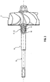
- Fig. 2 is a partially sectional view illustrative of a turbine rotor 10, before the rotor shaft 6 and the turbine wheel 5 are interconnected.
- connection part 12 which in Fig. 2 is shown in section. From this representation it is clear that the connection part 12 at the in Fig. 2 illustrated embodiment has a central bore 16 which is provided with a transverse to the central axis A of the rotor shaft 6 extending vent hole 13.
- the turbine wheel 5 has a fastening section, which in the exemplary case is designed as a pin 17.
- a fastening section which in the exemplary case is designed as a pin 17.
- the outer peripheral surface or lateral surface 14 of the pin 17 and the inner peripheral surface or inner lateral surface 15 of the bore 16 are illustrated, which together form a connecting device, which is formed according to the invention as a press connection.
- the dimension of the bore 16 and the pin 17 are inventively provided so that for the assembly of the rotor shaft 6 and turbine 5, an interference fit can be produced, which is designed according to DIN ISO 286 T2.
- it may be an interference fit H6 / r5.
- the finished turbine rotor assembly 10 is the Fig. 3 removable, wherein the vent hole 13 ensures that when joining the parts occurring sealing air, which would constitute an otherwise trapped air volume, can escape.
- the turbine wheel 5 is provided with a pin 17 and the rotor shaft 6 with a correspondingly dimensioned bore 16
- connection between these parts can also be produced by the reverse arrangement, ie by a rotor shaft 6 having a pin and a turbine wheel, the one includes appropriately trained bore.
- Fig. 4A-4C show cross-sections in the form of a dagger, which are marked with Q1, Q1 'and Q1 ".
- the cross section Q1 is a triangular equal thickness, through which terminus a cross section is shown, which represents a figure that is the same thickness for each direction.
- the cross-sectional shape Q1 represents the same thickness Fig. 4A with rounded corners.
- a pentagonal uniform thickness Q1 is shown by way of example In principle, other shapes, such as, in particular, a square equal thickness, are also conceivable.
- the turbine rotor 10 may preferably consist of the material TiAl and comprise a turbine wheel 5 produced by precision casting.
- the rotor shaft 6 in turn is preferably made of valve steel or heat-resistant, martensitic or austenitic steel.
- the inventive method for producing the turbine rotor 10 described above is characterized i.a. characterized in that without the use of an additional means, such as a solder, the connection between the two components 5 and 6 can be produced.
- the necessary to connect these parts 5, 6 fit is dependent on the size of the components 5, 6 and the load.
- Preferably required close tolerances of the pin 17 of the turbine wheel 5 can be achieved by grinding, which can be achieved that the turbine wheel 5 in the press fit on its joining surface has compressive stresses, which accommodates a possibly relatively brittle material behavior.
- the rotor shaft 6 is provided according to the invention with a precisely fitting bore 16. It is preferred that the pin of the turbine wheel has an insertion bevel or chamfer 18, which facilitates the joining of the two parts 5, 6.
- the material combination TiAl / steel can be chosen differently, although a valve steel is a preferred embodiment, as a result of relatively high thermal expansion coefficients between the turbine wheel 5 and the rotor shaft 6, which allow a secure bond over temperature.
- the interference fit results from the two contiguous peripheral surfaces or lateral surfaces 14 and 15 of the pin 17 and the bore 16, respectively, wherein for joining of the turbine wheel 5 and the rotor shaft 6, an additional joining device can be used, which distributes the shaft, when it is provided with the bore 16, evenly distributed around the circumference and the pin 17 of the turbine wheel 5 introduces into the evenly heated shaft and brings to a stop.
- both joining partners are joined together with a certain load, for example, 0.1 N / mm 2 or higher, but less than the yield stress of the turbine wheel 5 and the rotor shaft 6.
- the joining process may be carried out under a protective atmosphere, e.g. from in inert gas or reducing gas, take place in which one of the joining partners is heated by high-frequency heating to the necessary connection temperature.
- a protective atmosphere e.g. from in inert gas or reducing gas
- the shaft can be so strong cooled in a joining device with the aid of a strong temperature-reducing medium, such as liquid nitrogen until they into the bore 16 in the turbine wheel 5 fits.
- a strong temperature-reducing medium such as liquid nitrogen
- vent hole 13 is to be emphasized that minimally a bore, but also a plurality of such holes can be provided.
Claims (8)
- Turbocompresseur (1)- avec un compresseur (8), qui présente une roue de compresseur (9) qui est fixée sur une extrémité d'un arbre de rotor (6), et- avec une turbine (2), qui présente un rotor de turbine (10), qui comprend une roue de turbine (5) qui présente une partie de fixation (11), qui peut être assemblée à une partie de raccordement (12) de l'arbre de rotor (6) au moyen d'un dispositif d'assemblage (14, 15),caractérisé en ce que- le dispositif d'assemblage (14, 15) est formé par une combinaison d'un assemblage à ajustement serré et d'un assemblage par emboîtement, dans lequel la section transversale (Q1, Q1', Q1") de la partie de raccordement (12) est réalisée sous la forme d'une pièce d'épaisseur uniforme,- la partie de fixation (11) est formée par un alésage (16) et la partie de raccordement (12) est formée par un pivot (17), ou- la partie de fixation (11) est formée par un pivot (17) et la partie de raccordement (12) est formée par un alésage (16), et- l'alésage (16) est doté d'un trou d'aération (13).
- Turbocompresseur selon la revendication 1, caractérisé en ce que la pièce d'épaisseur uniforme (Q1') est réalisée sous forme de triangle curviligne.
- Turbocompresseur selon la revendication 1 ou 2, caractérisé en ce que la pièce d'épaisseur uniforme (Q1") est réalisée sous la forme d'un polygone d'épaisseur uniforme.
- Turbocompresseur selon l'une quelconque des revendications 1 à 3, caractérisé en ce que le matériau de la roue de turbine (5) est du TiAl.
- Turbocompresseur selon l'une quelconque des revendications 1 à 4, caractérisé en ce que le matériau de l'arbre de rotor (6) est un acier pour soupapes ou un acier martensitique, réfractaire ou austénitique.
- Procédé de fabrication d'un rotor de turbine (10) d'un turbocompresseur (1) selon la revendication 1, dans lequel le rotor de turbine (10) présente une roue de turbine (5), qui est dotée d'une partie de fixation (11), qui peut être assemblée à une partie de raccordement (12) d'un arbre de rotor (6) au moyen d'un dispositif d'assemblage (14, 15), caractérisé en ce que l'on choisit les dimensions et la forme de section transversale de la partie de fixation (11) et de la partie de raccordement (12) de telle manière qu'il en résulte un dispositif d'assemblage (14, 15) par assemblage combiné à ajustement serré et à emboîtement, dans lequel on réalise la partie de raccordement (12) de l'arbre de rotor (6) sous la forme d'un alésage (16) et on réalise la partie de fixation (11) sous la forme d'un pivot (17), dans lequel pour la réalisation de l'ajustement serré on chauffe l'alésage (16) de façon uniformément répartie à sa périphérie et on l'assemble ensuite avec le pivot (17), ou dans lequel on réalise la partie de fixation (11) sous la forme d'un alésage (16) et on réalise la partie de raccordement (12) de l'arbre de rotor (6) sous la forme d'un pivot, que l'on refroidit tellement fortement, avant l'assemblage afin de réaliser l'ajustement serré, qu'il soit possible de joindre l'alésage et le pivot, puis on produit l'assemblage par ajustement serré par chauffage du pivot, et dans lequel l'alésage (16) est doté d'un trou d'aération (13).
- Procédé selon la revendication 6, caractérisé en ce que l'on soumet l'arbre de rotor (6) à un tournage de dégrossissage ou à un tournage de finition.
- Procédé selon la revendication 6 ou 7, caractérisé en ce que l'on règle une profondeur de l'alésage (16) plus grande que la longueur du pivot (17) et le trou d'aération (13) est disposé dans une région de l'alésage (16) non couverte par le pivot (17) dans l'état assemblé de l'arbre de rotor (6) et de la roue de turbine (5).
Applications Claiming Priority (2)
| Application Number | Priority Date | Filing Date | Title |
|---|---|---|---|
| DE102006056386 | 2006-11-29 | ||
| PCT/EP2007/010301 WO2008064868A2 (fr) | 2006-11-29 | 2007-11-27 | Turbocompresseur |
Publications (2)
| Publication Number | Publication Date |
|---|---|
| EP2089611A2 EP2089611A2 (fr) | 2009-08-19 |
| EP2089611B1 true EP2089611B1 (fr) | 2018-10-10 |
Family
ID=39321638
Family Applications (1)
| Application Number | Title | Priority Date | Filing Date |
|---|---|---|---|
| EP07856267.5A Not-in-force EP2089611B1 (fr) | 2006-11-29 | 2007-11-27 | Turbocompresseur et procédé de fabrication correspondant |
Country Status (6)
| Country | Link |
|---|---|
| US (1) | US20100047072A1 (fr) |
| EP (1) | EP2089611B1 (fr) |
| JP (1) | JP2010511120A (fr) |
| KR (1) | KR20090082886A (fr) |
| CN (1) | CN101535600B (fr) |
| WO (1) | WO2008064868A2 (fr) |
Families Citing this family (28)
| Publication number | Priority date | Publication date | Assignee | Title |
|---|---|---|---|---|
| DE102008058503B4 (de) | 2008-11-21 | 2017-11-16 | Bosch Mahle Turbo Systems Gmbh & Co. Kg | Ladeeinrichtung |
| DE102008058508A1 (de) | 2008-11-21 | 2010-05-27 | Bosch Mahle Turbo Systems Gmbh & Co. Kg | Ladeeinrichtung |
| DE102008058507A1 (de) | 2008-11-21 | 2010-05-27 | Bosch Mahle Turbo Systems Gmbh & Co. Kg | Ladeeinrichtung |
| DE102008058504A1 (de) | 2008-11-21 | 2010-05-27 | Bosch Mahle Turbo Systems Gmbh & Co. Kg | Ladeeinrichtung |
| DE102008058506A1 (de) | 2008-11-21 | 2010-05-27 | Bosch Mahle Turbo Systems Gmbh & Co. Kg | Ladeeinrichtung |
| JP5218226B2 (ja) * | 2009-04-02 | 2013-06-26 | 株式会社Ihi | ロータの製造方法、ロータ及びターボチャージャ |
| DE102009023449A1 (de) * | 2009-05-30 | 2010-12-16 | Piv Drives Gmbh | Wellen-Naben-Verbindung mit Polygonprofil |
| DE102010031399A1 (de) | 2010-07-15 | 2012-01-19 | Hilti Aktiengesellschaft | Rotor für einen Elektromotor, Elektromotor und Herstellungsverfahren für einen Elektromotor |
| US20120076639A1 (en) * | 2010-09-27 | 2012-03-29 | Nicolas Vazeille | Shaft and Turbine Wheel Assembly |
| JP2014533339A (ja) * | 2011-11-15 | 2014-12-11 | ボーグワーナー インコーポレーテッド | フローロータ、特にタービンホイール |
| JP6111260B2 (ja) * | 2011-11-23 | 2017-04-05 | ボーグワーナー インコーポレーテッド | 排気ガスターボチャージャ |
| US20150050126A1 (en) * | 2012-03-01 | 2015-02-19 | Borgwarner Inc. | Exhaust-gas turbocharger |
| DE112013000963T5 (de) * | 2012-03-15 | 2014-11-06 | Borgwarner Inc. | Abgasturbolader |
| DE102012207271A1 (de) * | 2012-05-02 | 2013-11-07 | Robert Bosch Gmbh | Verfahren zum Verbinden einer Welle mit einem Rotationsbauteil und nach diesem Verfahren hergestellte Turboladerwelle |
| CN102767398A (zh) * | 2012-07-04 | 2012-11-07 | 联优机械(常熟)有限公司 | 透平膨胀机的叶轮与主轴的配合结构 |
| US20150336431A1 (en) * | 2012-12-28 | 2015-11-26 | Michelin Recherche Et Technique S.A. | Pneumatic tire tread and pneumatic tire having said tread |
| DE102013207420B4 (de) | 2013-04-24 | 2018-12-27 | Schaeffler Technologies AG & Co. KG | Verfahren zum Spannen und Bearbeiten eines Turbinenrades für einen Turbolader |
| CN103362557B (zh) * | 2013-08-05 | 2016-04-20 | 汉美综合科技(常州)有限公司 | 一种叶轮与涡轮轴的连接结构 |
| CN103438058B (zh) * | 2013-08-28 | 2016-02-24 | 中国北方发动机研究所(天津) | 钛铝增压器涡轮转轴的螺纹过盈锁紧连接结构 |
| DE102013223999A1 (de) * | 2013-11-25 | 2015-05-28 | Mahle International Gmbh | Flügelzellenpumpe oder Pendelschieberpumpe |
| JP2016063599A (ja) * | 2014-09-17 | 2016-04-25 | ナブテスコ株式会社 | 減速機付モータ |
| DE102016100819A1 (de) * | 2015-02-20 | 2016-08-25 | Abb Turbo Systems Ag | Kupplungsvorrichtung |
| FR3059739B1 (fr) * | 2016-12-01 | 2019-07-19 | Airbus Safran Launchers Sas | Organe rotatif et procede de frettage |
| DE102017104001A1 (de) * | 2017-02-27 | 2018-08-30 | Man Diesel & Turbo Se | Turbolader |
| JP2019082170A (ja) * | 2017-10-31 | 2019-05-30 | ボーグワーナー インコーポレーテッド | ポリマ圧縮機ホイール組立体 |
| CN108487993B (zh) * | 2018-02-28 | 2020-05-01 | 深圳意动航空科技有限公司 | 一种转子结构及发动机 |
| CN108626167A (zh) * | 2018-04-28 | 2018-10-09 | 江苏锡宇汽车有限公司 | 加固型涡轮增压器转子总成 |
| CN114776386B (zh) * | 2022-04-29 | 2023-05-19 | 中国北方发动机研究所(天津) | 一种钛铝涡轮与转轴的锥体连接结构 |
Citations (1)
| Publication number | Priority date | Publication date | Assignee | Title |
|---|---|---|---|---|
| US5339521A (en) * | 1992-03-26 | 1994-08-23 | Ngk Insulators, Ltd. | Machining method of ceramic turbine rotor |
Family Cites Families (20)
| Publication number | Priority date | Publication date | Assignee | Title |
|---|---|---|---|---|
| DE2436270A1 (de) * | 1974-07-27 | 1976-02-05 | Motoren Turbinen Union | Wellenverbindung |
| US4357137A (en) * | 1980-08-18 | 1982-11-02 | Arinc Research Corporation | Shaft coupling |
| US4411634A (en) * | 1980-11-10 | 1983-10-25 | The Bendix Corporation | Flexible coupling having molded plastic flexible diaphragms |
| US4340317A (en) * | 1981-05-07 | 1982-07-20 | Northern Research & Engineering Corp. | Splineless coupling means |
| US4719074A (en) * | 1984-03-29 | 1988-01-12 | Ngk Insulators, Ltd. | Metal-ceramic composite article and a method of producing the same |
| US4809420A (en) * | 1987-12-16 | 1989-03-07 | Fatigue Technology, Inc. | Method and apparatus for backing up mandrel exit holes in knuckle structures |
| JPH0280701U (fr) * | 1988-12-08 | 1990-06-21 | ||
| JPH03260330A (ja) * | 1990-03-09 | 1991-11-20 | Toyota Motor Corp | ターボチャージャのロータ |
| JPH0476381U (fr) * | 1990-11-09 | 1992-07-03 | ||
| JPH0825879A (ja) * | 1994-07-20 | 1996-01-30 | Isao Shirayanagi | 卓上ペン立て |
| EP0837221B1 (fr) * | 1996-10-18 | 2003-09-10 | Daido Steel Company Limited | Rotor de turbine à base de Ti-Al et procédé de fabrication dudit rotor. |
| JPH11126416A (ja) * | 1997-10-20 | 1999-05-11 | Hitachi Ltd | ディスク装置 |
| JP2000266980A (ja) * | 1999-03-19 | 2000-09-29 | Fuji Photo Optical Co Ltd | レンズ保持枠 |
| US6499958B2 (en) * | 1999-07-02 | 2002-12-31 | Ingersoll-Rand Company | Device and method for detachably connecting an impeller to a pinion shaft in a high speed fluid compressor |
| JP2001199106A (ja) * | 2000-01-24 | 2001-07-24 | Seiko Epson Corp | 動力伝達体及びこの動力伝達体を用いた記録装置並びにそのシート搬送機構 |
| US6364634B1 (en) * | 2000-09-29 | 2002-04-02 | General Motors Corporation | Turbocharger rotor with alignment couplings |
| DE10209347B4 (de) * | 2002-03-02 | 2005-12-08 | Daimlerchrysler Ag | Herstellungsverfahren für einen Turbinenradläufer |
| US7033156B2 (en) * | 2002-04-11 | 2006-04-25 | Luka Gakovic | Ceramic center pin for compaction tooling and method for making same |
| US7241416B2 (en) * | 2003-08-12 | 2007-07-10 | Borg Warner Inc. | Metal injection molded turbine rotor and metal injection molded shaft connection attachment thereto |
| US7287960B2 (en) * | 2004-07-28 | 2007-10-30 | B{dot over (o)}rgWarner, Inc. | Titanium aluminide wheel and steel shaft connection thereto |
-
2007
- 2007-11-27 KR KR1020097008522A patent/KR20090082886A/ko not_active Application Discontinuation
- 2007-11-27 EP EP07856267.5A patent/EP2089611B1/fr not_active Not-in-force
- 2007-11-27 US US12/515,434 patent/US20100047072A1/en not_active Abandoned
- 2007-11-27 JP JP2009538633A patent/JP2010511120A/ja active Pending
- 2007-11-27 WO PCT/EP2007/010301 patent/WO2008064868A2/fr active Application Filing
- 2007-11-27 CN CN200780041891.3A patent/CN101535600B/zh not_active Expired - Fee Related
Patent Citations (1)
| Publication number | Priority date | Publication date | Assignee | Title |
|---|---|---|---|---|
| US5339521A (en) * | 1992-03-26 | 1994-08-23 | Ngk Insulators, Ltd. | Machining method of ceramic turbine rotor |
Also Published As
| Publication number | Publication date |
|---|---|
| CN101535600B (zh) | 2014-03-12 |
| US20100047072A1 (en) | 2010-02-25 |
| KR20090082886A (ko) | 2009-07-31 |
| WO2008064868A3 (fr) | 2008-07-17 |
| WO2008064868A2 (fr) | 2008-06-05 |
| JP2010511120A (ja) | 2010-04-08 |
| CN101535600A (zh) | 2009-09-16 |
| EP2089611A2 (fr) | 2009-08-19 |
Similar Documents
| Publication | Publication Date | Title |
|---|---|---|
| EP2089611B1 (fr) | Turbocompresseur et procédé de fabrication correspondant | |
| EP1053388B1 (fr) | Soupape legere | |
| DE102008008857B4 (de) | Verbindung einer Welle mit einem Rotationsbauteil | |
| DE2728823A1 (de) | Gasturbine | |
| DE102012205042A1 (de) | Turbinenläufer für eine Abgasturbine sowie ein Verfahren zur Herstellung des Turbinenläufers | |
| EP2574807B1 (fr) | Raccordement entre un arbre et un composant de moyeu ainsi que procédé de fabrication du raccordement | |
| DE102007012641A1 (de) | Laufzeug für einen Abgasturbolader | |
| DE102015216319A1 (de) | Turboladerläufer für einen Abgasturbolader und Abgasturbolader | |
| DE102015007470A1 (de) | Verfahren zum Herstellen einer Welle-Nabe-Verbindung | |
| DE102008050471A1 (de) | Geteiltes Zahnrad | |
| DE102009029781B4 (de) | Bremsscheibe und Verfahren zu deren Herstellung | |
| DE10354085B4 (de) | Leichtbauventil | |
| DE102006008836A1 (de) | Verfahren zur Herstellung und/oder Reparatur eines integral beschaufelten Rotors | |
| DE102012212990A1 (de) | Welle-Nabeverbindung eines Läufers | |
| WO2012107915A1 (fr) | Procédé de fabrication d'une pièce métallique soudée par friction et pièce métallique soudée par friction fabriquée selon ledit procédé | |
| DE102013006890A1 (de) | Verfahren zum Herstellen einer Kurbelwelle für einen Verbrennungsmotor | |
| DE3005058A1 (de) | Radialturbinenlaeufer | |
| DE102012217560A1 (de) | Turbinenläufer mit Hülsenzwischenstück, Abgasturbolader und ein Verfahren zur Herstellung des Turbinenläufers | |
| DE102004053289A1 (de) | Vakuumpumpen-Laufrad | |
| DE102009034420A1 (de) | Vorrichtung zum Fügen eines Turbinenrades mit einer Welle | |
| EP3699442B1 (fr) | Arbre | |
| DE102013008658A1 (de) | Antriebselement mit einem Kegelrad für einen Kraftwagen sowie Verfahren zum Herstellen eines solchen Antriebselements | |
| DE60309981T2 (de) | Verfahren und Vorrichtung zur Herstellung von Rotorwellen | |
| DE3110096C2 (de) | Turbinenlaufschaufel für Gasturbinentriebwerke | |
| DE10234539B4 (de) | Kolben mit einem offen vergossenen Kühlkanal-Ringträger und Verfahren zu seiner Herstellung |
Legal Events
| Date | Code | Title | Description |
|---|---|---|---|
| PUAI | Public reference made under article 153(3) epc to a published international application that has entered the european phase |
Free format text: ORIGINAL CODE: 0009012 |
|
| 17P | Request for examination filed |
Effective date: 20090609 |
|
| AK | Designated contracting states |
Kind code of ref document: A2 Designated state(s): AT BE BG CH CY CZ DE DK EE ES FI FR GB GR HU IE IS IT LI LT LU LV MC MT NL PL PT RO SE SI SK TR |
|
| DAX | Request for extension of the european patent (deleted) | ||
| STAA | Information on the status of an ep patent application or granted ep patent |
Free format text: STATUS: EXAMINATION IS IN PROGRESS |
|
| 17Q | First examination report despatched |
Effective date: 20161115 |
|
| GRAP | Despatch of communication of intention to grant a patent |
Free format text: ORIGINAL CODE: EPIDOSNIGR1 |
|
| STAA | Information on the status of an ep patent application or granted ep patent |
Free format text: STATUS: GRANT OF PATENT IS INTENDED |
|
| INTG | Intention to grant announced |
Effective date: 20180508 |
|
| GRAS | Grant fee paid |
Free format text: ORIGINAL CODE: EPIDOSNIGR3 |
|
| GRAA | (expected) grant |
Free format text: ORIGINAL CODE: 0009210 |
|
| STAA | Information on the status of an ep patent application or granted ep patent |
Free format text: STATUS: THE PATENT HAS BEEN GRANTED |
|
| AK | Designated contracting states |
Kind code of ref document: B1 Designated state(s): AT BE BG CH CY CZ DE DK EE ES FI FR GB GR HU IE IS IT LI LT LU LV MC MT NL PL PT RO SE SI SK TR |
|
| REG | Reference to a national code |
Ref country code: GB Ref legal event code: FG4D Free format text: NOT ENGLISH |
|
| REG | Reference to a national code |
Ref country code: CH Ref legal event code: EP Ref country code: AT Ref legal event code: REF Ref document number: 1051476 Country of ref document: AT Kind code of ref document: T Effective date: 20181015 |
|
| REG | Reference to a national code |
Ref country code: FR Ref legal event code: PLFP Year of fee payment: 12 |
|
| REG | Reference to a national code |
Ref country code: IE Ref legal event code: FG4D Free format text: LANGUAGE OF EP DOCUMENT: GERMAN |
|
| REG | Reference to a national code |
Ref country code: DE Ref legal event code: R096 Ref document number: 502007016434 Country of ref document: DE |
|
| REG | Reference to a national code |
Ref country code: NL Ref legal event code: MP Effective date: 20181010 |
|
| REG | Reference to a national code |
Ref country code: LT Ref legal event code: MG4D |
|
| PG25 | Lapsed in a contracting state [announced via postgrant information from national office to epo] |
Ref country code: NL Free format text: LAPSE BECAUSE OF FAILURE TO SUBMIT A TRANSLATION OF THE DESCRIPTION OR TO PAY THE FEE WITHIN THE PRESCRIBED TIME-LIMIT Effective date: 20181010 |
|
| PG25 | Lapsed in a contracting state [announced via postgrant information from national office to epo] |
Ref country code: ES Free format text: LAPSE BECAUSE OF FAILURE TO SUBMIT A TRANSLATION OF THE DESCRIPTION OR TO PAY THE FEE WITHIN THE PRESCRIBED TIME-LIMIT Effective date: 20181010 Ref country code: LV Free format text: LAPSE BECAUSE OF FAILURE TO SUBMIT A TRANSLATION OF THE DESCRIPTION OR TO PAY THE FEE WITHIN THE PRESCRIBED TIME-LIMIT Effective date: 20181010 Ref country code: PL Free format text: LAPSE BECAUSE OF FAILURE TO SUBMIT A TRANSLATION OF THE DESCRIPTION OR TO PAY THE FEE WITHIN THE PRESCRIBED TIME-LIMIT Effective date: 20181010 Ref country code: BG Free format text: LAPSE BECAUSE OF FAILURE TO SUBMIT A TRANSLATION OF THE DESCRIPTION OR TO PAY THE FEE WITHIN THE PRESCRIBED TIME-LIMIT Effective date: 20190110 Ref country code: LT Free format text: LAPSE BECAUSE OF FAILURE TO SUBMIT A TRANSLATION OF THE DESCRIPTION OR TO PAY THE FEE WITHIN THE PRESCRIBED TIME-LIMIT Effective date: 20181010 Ref country code: IS Free format text: LAPSE BECAUSE OF FAILURE TO SUBMIT A TRANSLATION OF THE DESCRIPTION OR TO PAY THE FEE WITHIN THE PRESCRIBED TIME-LIMIT Effective date: 20190210 Ref country code: FI Free format text: LAPSE BECAUSE OF FAILURE TO SUBMIT A TRANSLATION OF THE DESCRIPTION OR TO PAY THE FEE WITHIN THE PRESCRIBED TIME-LIMIT Effective date: 20181010 |
|
| PG25 | Lapsed in a contracting state [announced via postgrant information from national office to epo] |
Ref country code: SE Free format text: LAPSE BECAUSE OF FAILURE TO SUBMIT A TRANSLATION OF THE DESCRIPTION OR TO PAY THE FEE WITHIN THE PRESCRIBED TIME-LIMIT Effective date: 20181010 Ref country code: GR Free format text: LAPSE BECAUSE OF FAILURE TO SUBMIT A TRANSLATION OF THE DESCRIPTION OR TO PAY THE FEE WITHIN THE PRESCRIBED TIME-LIMIT Effective date: 20190111 Ref country code: PT Free format text: LAPSE BECAUSE OF FAILURE TO SUBMIT A TRANSLATION OF THE DESCRIPTION OR TO PAY THE FEE WITHIN THE PRESCRIBED TIME-LIMIT Effective date: 20190210 |
|
| REG | Reference to a national code |
Ref country code: CH Ref legal event code: PL |
|
| REG | Reference to a national code |
Ref country code: DE Ref legal event code: R097 Ref document number: 502007016434 Country of ref document: DE |
|
| PG25 | Lapsed in a contracting state [announced via postgrant information from national office to epo] |
Ref country code: CZ Free format text: LAPSE BECAUSE OF FAILURE TO SUBMIT A TRANSLATION OF THE DESCRIPTION OR TO PAY THE FEE WITHIN THE PRESCRIBED TIME-LIMIT Effective date: 20181010 Ref country code: DK Free format text: LAPSE BECAUSE OF FAILURE TO SUBMIT A TRANSLATION OF THE DESCRIPTION OR TO PAY THE FEE WITHIN THE PRESCRIBED TIME-LIMIT Effective date: 20181010 Ref country code: IT Free format text: LAPSE BECAUSE OF FAILURE TO SUBMIT A TRANSLATION OF THE DESCRIPTION OR TO PAY THE FEE WITHIN THE PRESCRIBED TIME-LIMIT Effective date: 20181010 Ref country code: LU Free format text: LAPSE BECAUSE OF NON-PAYMENT OF DUE FEES Effective date: 20181127 |
|
| PLBE | No opposition filed within time limit |
Free format text: ORIGINAL CODE: 0009261 |
|
| STAA | Information on the status of an ep patent application or granted ep patent |
Free format text: STATUS: NO OPPOSITION FILED WITHIN TIME LIMIT |
|
| REG | Reference to a national code |
Ref country code: BE Ref legal event code: MM Effective date: 20181130 |
|
| REG | Reference to a national code |
Ref country code: IE Ref legal event code: MM4A |
|
| PG25 | Lapsed in a contracting state [announced via postgrant information from national office to epo] |
Ref country code: SK Free format text: LAPSE BECAUSE OF FAILURE TO SUBMIT A TRANSLATION OF THE DESCRIPTION OR TO PAY THE FEE WITHIN THE PRESCRIBED TIME-LIMIT Effective date: 20181010 Ref country code: RO Free format text: LAPSE BECAUSE OF FAILURE TO SUBMIT A TRANSLATION OF THE DESCRIPTION OR TO PAY THE FEE WITHIN THE PRESCRIBED TIME-LIMIT Effective date: 20181010 Ref country code: CH Free format text: LAPSE BECAUSE OF NON-PAYMENT OF DUE FEES Effective date: 20181130 Ref country code: MC Free format text: LAPSE BECAUSE OF FAILURE TO SUBMIT A TRANSLATION OF THE DESCRIPTION OR TO PAY THE FEE WITHIN THE PRESCRIBED TIME-LIMIT Effective date: 20181010 Ref country code: LI Free format text: LAPSE BECAUSE OF NON-PAYMENT OF DUE FEES Effective date: 20181130 Ref country code: EE Free format text: LAPSE BECAUSE OF FAILURE TO SUBMIT A TRANSLATION OF THE DESCRIPTION OR TO PAY THE FEE WITHIN THE PRESCRIBED TIME-LIMIT Effective date: 20181010 |
|
| 26N | No opposition filed |
Effective date: 20190711 |
|
| PG25 | Lapsed in a contracting state [announced via postgrant information from national office to epo] |
Ref country code: SI Free format text: LAPSE BECAUSE OF FAILURE TO SUBMIT A TRANSLATION OF THE DESCRIPTION OR TO PAY THE FEE WITHIN THE PRESCRIBED TIME-LIMIT Effective date: 20181010 Ref country code: IE Free format text: LAPSE BECAUSE OF NON-PAYMENT OF DUE FEES Effective date: 20181127 |
|
| PG25 | Lapsed in a contracting state [announced via postgrant information from national office to epo] |
Ref country code: BE Free format text: LAPSE BECAUSE OF NON-PAYMENT OF DUE FEES Effective date: 20181130 |
|
| REG | Reference to a national code |
Ref country code: AT Ref legal event code: MM01 Ref document number: 1051476 Country of ref document: AT Kind code of ref document: T Effective date: 20181127 |
|
| PG25 | Lapsed in a contracting state [announced via postgrant information from national office to epo] |
Ref country code: MT Free format text: LAPSE BECAUSE OF FAILURE TO SUBMIT A TRANSLATION OF THE DESCRIPTION OR TO PAY THE FEE WITHIN THE PRESCRIBED TIME-LIMIT Effective date: 20181010 Ref country code: AT Free format text: LAPSE BECAUSE OF NON-PAYMENT OF DUE FEES Effective date: 20181127 |
|
| PGFP | Annual fee paid to national office [announced via postgrant information from national office to epo] |
Ref country code: DE Payment date: 20191017 Year of fee payment: 13 |
|
| PGFP | Annual fee paid to national office [announced via postgrant information from national office to epo] |
Ref country code: FR Payment date: 20191029 Year of fee payment: 13 |
|
| PG25 | Lapsed in a contracting state [announced via postgrant information from national office to epo] |
Ref country code: TR Free format text: LAPSE BECAUSE OF FAILURE TO SUBMIT A TRANSLATION OF THE DESCRIPTION OR TO PAY THE FEE WITHIN THE PRESCRIBED TIME-LIMIT Effective date: 20181010 |
|
| PGFP | Annual fee paid to national office [announced via postgrant information from national office to epo] |
Ref country code: GB Payment date: 20191029 Year of fee payment: 13 |
|
| PG25 | Lapsed in a contracting state [announced via postgrant information from national office to epo] |
Ref country code: CY Free format text: LAPSE BECAUSE OF FAILURE TO SUBMIT A TRANSLATION OF THE DESCRIPTION OR TO PAY THE FEE WITHIN THE PRESCRIBED TIME-LIMIT Effective date: 20181010 Ref country code: HU Free format text: LAPSE BECAUSE OF FAILURE TO SUBMIT A TRANSLATION OF THE DESCRIPTION OR TO PAY THE FEE WITHIN THE PRESCRIBED TIME-LIMIT; INVALID AB INITIO Effective date: 20071127 |
|
| REG | Reference to a national code |
Ref country code: DE Ref legal event code: R119 Ref document number: 502007016434 Country of ref document: DE |
|
| GBPC | Gb: european patent ceased through non-payment of renewal fee |
Effective date: 20201127 |
|
| PG25 | Lapsed in a contracting state [announced via postgrant information from national office to epo] |
Ref country code: FR Free format text: LAPSE BECAUSE OF NON-PAYMENT OF DUE FEES Effective date: 20201130 |
|
| PG25 | Lapsed in a contracting state [announced via postgrant information from national office to epo] |
Ref country code: GB Free format text: LAPSE BECAUSE OF NON-PAYMENT OF DUE FEES Effective date: 20201127 Ref country code: DE Free format text: LAPSE BECAUSE OF NON-PAYMENT OF DUE FEES Effective date: 20210601 |