EP1052159A2 - Coupe-circuit pour fluide sous pression pour direction assistée dans les positions extrêmes d'angle de braquage - Google Patents
Coupe-circuit pour fluide sous pression pour direction assistée dans les positions extrêmes d'angle de braquage Download PDFInfo
- Publication number
- EP1052159A2 EP1052159A2 EP00104895A EP00104895A EP1052159A2 EP 1052159 A2 EP1052159 A2 EP 1052159A2 EP 00104895 A EP00104895 A EP 00104895A EP 00104895 A EP00104895 A EP 00104895A EP 1052159 A2 EP1052159 A2 EP 1052159A2
- Authority
- EP
- European Patent Office
- Prior art keywords
- steering
- bore
- spring
- shut
- stop means
- Prior art date
- Legal status (The legal status is an assumption and is not a legal conclusion. Google has not performed a legal analysis and makes no representation as to the accuracy of the status listed.)
- Granted
Links
Images

Classifications
-
- B—PERFORMING OPERATIONS; TRANSPORTING
- B62—LAND VEHICLES FOR TRAVELLING OTHERWISE THAN ON RAILS
- B62D—MOTOR VEHICLES; TRAILERS
- B62D5/00—Power-assisted or power-driven steering
- B62D5/06—Power-assisted or power-driven steering fluid, i.e. using a pressurised fluid for most or all the force required for steering a vehicle
- B62D5/061—Power-assisted or power-driven steering fluid, i.e. using a pressurised fluid for most or all the force required for steering a vehicle provided with effort, steering lock, or end-of-stroke limiters
Definitions
- the invention relates to a pressure cut-off device for an assistant steering in the end positions of the Steering deflection with the features of the generic term of Claim 1.
- pressure cut-off devices are known from the prior art. So shows for example EP 0321756 A2 a recirculating ball steering, where the working piston two in the axial direction Actuated seat valves carries in the end positions of the permitted steering deflection on the housing and the one that is pressurized Reduce the existing work pressure.
- the auxiliary support is no longer available, so that a further turning of the steering is not possible is.
- shut-off valves hit the extreme positions to a stop in the shape of a towards the Valves for spring-loaded pins.
- the pen can be in Radial direction can be secured with a clamping screw.
- This steering For setting the opening point of the shut-off valves and thus for setting the stop limits it is necessary for this steering to tighten the clamping screw loosen and the steering manually with relieved wheels to operate at the maximum allowable steering angle.
- This causes the shut-off valve to be spring-loaded Push the pin into the required position. The pin can then be secured in this position and is therefore permanently set.
- the sling means by means of a radial acting spring with an opening force of Shut-off valves exceeding holding force are fixed, can do this by manual procedure of Shut-off valves against the lifting gear on the required setting are brought. Also a Repeatedly moving the sling does not lead to a substantial drop in the holding force of the radial spring. It is advantageous if the sling a has essential round shaft area and the spring surrounds the shaft area in a ring. This causes besides a good holding force also about the circumference even distribution of this holding force and a certain guidance of the lifting gear. If the spring is one circumferential band spring with a wave-like in the circumferential direction Profile is a particularly high holding force achieved simultaneous centering of the lifting gear become.
- the lifting gear is in one Bore, for example a through hole of the Steering housing or a bore of a separate holder are guided, preferably each through hole a removable fluid and pressure tight closure has, after its removal, the steering housing opposite end of the respective sling from the outside is accessible.
- the sling can then be moved in manually a basic position can be moved from which the Setting is done.
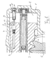
- FIG. 1 shows a section of a Recirculating ball steering in a cross section.
- a Steering housing 1 shown that a working piston 2nd contains and leads in the axial direction and with this one first workspace I limited.
- the working piston 2 carries a toothing 3 with a corresponding pinion 4th a steering shaft 5 combs.
- the working piston 2 carries on a channel 6 with shut-off valves 7.
- the Shut-off valve 7 In the wall of the Steering housing 1 is further in the axial direction with the Shut-off valve 7 in alignment with a banjo bolt 10 with a inner through hole 11 arranged.
- Stop bolt 12 out of the shutoff valve 7th facing a tip 13 and the hollow screw 10th facing a radial spring 14 carries.
- the bore 11 of the Banjo bolt 10 is on the outside of the housing a screw plug 15 liquid and pressure tight locked.
- the stop pin 12 is in the Representation according to Figure 1 in its left Extreme position. A pressure equalization between the Working space I and the bore 11 inside the Banjo bolt 10 is by a not shown Relief bore or groove guaranteed.
- FIG. 2 shows the steering system according to FIG. 1, the same features have the same reference numerals.
- the axially displaceable stop pin 12 here Setting an end stop in a middle position moved within the bore 11 of the banjo bolt 10 is.
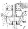
- Figure 3 is the area facing the steering column the steering shown in Figure 1 and Figure 2.
- a second work area II Channel 6 carries a second shutoff valve 17, the axially aligned with a second through hole 21 and a stop pin 22 mounted therein is.
- the stop pin 22 carries a valve 17 facing tip 23 and is by means of a radial spring 24th stored in the through hole 21.
- the Through hole 21 is here directly in one Valve housing 25 introduced and by one Screw closure 26 closed fluid and pressure tight.
- the closure 26 can be identical to the closure 15 of the banjo bolt 10 to be executed.
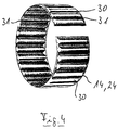
- FIG. 4 shows a radial spring 14, 24 in a perspective view. It can be seen that the radial spring is an annular, open on one side Band spring with all-round, wavy structure 30 is. The wavy structure is in this Embodiment pronounced trapezoidal, with a Edge region 31 of the radial spring 14, 24 is free of the profile is.
- the work area II is pressurized.
- the working piston 2 is in the representation of the Figures 1 to 3 pushed to the right.
- the one in the work room II applied fluid pressure opens the spring-loaded One-way valve 17, so that essentially in the channel 6 the same pressure is applied as in workroom II
- One-way valve 7 is in its closing direction from this Pressurized so that no pressure drop at valve 7 occurs and the fluid pressure present in work area II is maintained.
- the working piston 2 so is moved far to the right that the valve 7 with the Tip 13 of the stop pin 12 comes into contact the valve 7 opened.
- the Servo support is also essentially eliminated.
- the position of the stop bolts 12, 22 and in particular the tips 13, 23 in the bores 11, 21 is therefore for the maximum available travel of the working piston 2 and thus for the maximum swivel angle of the steering shaft 5 decisive.
- the working piston 2 can relieve the steered axle of the motor vehicle manually in Axial direction to be moved to the stop. On low residual pressure of 20 to 40 bar supports this Movement, however, is insignificant when the axis is loaded.
- the stop pin 12, 22 comes in mechanical contact with the base body of the valve 7, 17 and pushes the stop pin 12, 22 into the bore 11, 21 into it.
- the holding force within the Hole 11, 21 overcome by the radial Preload of the radial spring 15, 24 is applied.
- This process is used to preset the point on which the servo support in operation by opening the Valves 7, 17 should actually be omitted, that is to say Setting the effective end stops of the Steering. In many cases, these end stops can only be set in the motor vehicle itself, since the Installation conditions and, if necessary, the tires make individual adjustment necessary.
- the radial springs in FIG. 4 are particularly suitable illustrated so-called tolerance rings or Radial shaft rings that are commercially available and usually to create a shaft-hub connection serve.
- tolerance rings are for example from Rencol Tolerance Rings Ltd., Great Britain Respectively.
Landscapes
- Engineering & Computer Science (AREA)
- Chemical & Material Sciences (AREA)
- Combustion & Propulsion (AREA)
- Transportation (AREA)
- Mechanical Engineering (AREA)
- Power Steering Mechanism (AREA)
Applications Claiming Priority (2)
| Application Number | Priority Date | Filing Date | Title |
|---|---|---|---|
| DE19921553A DE19921553A1 (de) | 1999-05-11 | 1999-05-11 | Druckabschalteinrichtung für eine Hilfskraftlenkung in den Endstellungen des Lenkausschlages |
| DE19921553 | 1999-05-11 |
Publications (3)
| Publication Number | Publication Date |
|---|---|
| EP1052159A2 true EP1052159A2 (fr) | 2000-11-15 |
| EP1052159A3 EP1052159A3 (fr) | 2001-04-04 |
| EP1052159B1 EP1052159B1 (fr) | 2003-10-01 |
Family
ID=7907624
Family Applications (1)
| Application Number | Title | Priority Date | Filing Date |
|---|---|---|---|
| EP00104895A Expired - Lifetime EP1052159B1 (fr) | 1999-05-11 | 2000-03-08 | Coupe-circuit pour fluide sous pression pour direction assistée dans les positions extrêmes d'angle de braquage |
Country Status (6)
| Country | Link |
|---|---|
| US (1) | US6318232B1 (fr) |
| EP (1) | EP1052159B1 (fr) |
| JP (1) | JP2000344119A (fr) |
| BR (1) | BR0001690A (fr) |
| DE (2) | DE19921553A1 (fr) |
| ES (1) | ES2204378T3 (fr) |
Cited By (2)
| Publication number | Priority date | Publication date | Assignee | Title |
|---|---|---|---|---|
| WO2008132125A1 (fr) | 2007-04-27 | 2008-11-06 | Zf Lenksysteme Gmbh | Dispositif de direction assistée pour véhicule |
| EP3789643A3 (fr) * | 2019-09-09 | 2021-07-28 | AUMA Riester GmbH & Co. KG | Servomoteurs et utilisation d'une bague de tolérance et/ou d'un manchon de tolérance |
Families Citing this family (7)
| Publication number | Priority date | Publication date | Assignee | Title |
|---|---|---|---|---|
| DE10004670B4 (de) * | 2000-02-03 | 2010-12-09 | Thyssenkrupp Presta Steertec Gmbh | Druckabschalteinrichtung für eine Hilfskraftlenkung in den Endstellungen des Lenkausschlages |
| US7007386B1 (en) | 2002-12-20 | 2006-03-07 | General Sullivan Group, Inc. | Light duty bearing assembly |
| JP5592319B2 (ja) * | 2011-08-22 | 2014-09-17 | 日立オートモティブシステムズステアリング株式会社 | インテグラル型パワーステアリング装置 |
| CN103241287A (zh) * | 2013-05-07 | 2013-08-14 | 常州机电职业技术学院 | 一种液压转向系统压力调节装置 |
| DE102014117327A1 (de) * | 2014-11-26 | 2016-06-02 | Robert Bosch Automotive Steering Gmbh | Lenksystem für ein Kraftfahrzeug und Verfahren zum Entlüften eines Lenksystems für ein Kraftfahrzeug |
| WO2018222845A1 (fr) * | 2017-05-31 | 2018-12-06 | R.H. Sheppard Co., Inc. | Ensemble piston destiné à un mécanisme de direction assistée |
| CN111148911B (zh) | 2017-08-16 | 2022-03-29 | 多媒体股份有限公司 | 带有注射模制支承件的球形接头 |
Citations (2)
| Publication number | Priority date | Publication date | Assignee | Title |
|---|---|---|---|---|
| EP0321756A2 (fr) | 1987-12-21 | 1989-06-28 | Trw Inc. | Procédé et dispositif pour modifier le réglage de soupapes de surpression à champignon |
| DE4127610A1 (de) | 1990-08-24 | 1992-02-27 | Zahnradfabrik Friedrichshafen | Hydraulische hilfskraftlenkung |
Family Cites Families (6)
| Publication number | Priority date | Publication date | Assignee | Title |
|---|---|---|---|---|
| US4177714A (en) * | 1977-10-25 | 1979-12-11 | General Motors Corporation | Torsion bar for power steering gear |
| GB2151996B (en) * | 1983-12-09 | 1987-04-23 | Trw Cam Gears Ltd | Power assisted steering system |
| DE3902808A1 (de) * | 1988-02-04 | 1989-08-17 | Zahnradfabrik Friedrichshafen | Hydraulische hilfskraftlenkung |
| WO1994008834A1 (fr) | 1992-10-15 | 1994-04-28 | Bendix España S.A. | Dispositif de commande hydraulique a valve mobile |
| US5419235A (en) * | 1994-02-28 | 1995-05-30 | Trw Inc. | Power steering gear assembly |
| US5803201A (en) * | 1996-06-05 | 1998-09-08 | R. H. Sheppard Co., Inc. | Hydraulic power steering gear assembly with unloading valve |
-
1999
- 1999-05-11 DE DE19921553A patent/DE19921553A1/de not_active Withdrawn
-
2000
- 2000-03-08 ES ES00104895T patent/ES2204378T3/es not_active Expired - Lifetime
- 2000-03-08 DE DE50003875T patent/DE50003875D1/de not_active Expired - Lifetime
- 2000-03-08 EP EP00104895A patent/EP1052159B1/fr not_active Expired - Lifetime
- 2000-04-27 BR BR0001690-0A patent/BR0001690A/pt not_active Application Discontinuation
- 2000-05-10 JP JP2000137662A patent/JP2000344119A/ja active Pending
- 2000-05-11 US US09/568,725 patent/US6318232B1/en not_active Expired - Fee Related
Patent Citations (2)
| Publication number | Priority date | Publication date | Assignee | Title |
|---|---|---|---|---|
| EP0321756A2 (fr) | 1987-12-21 | 1989-06-28 | Trw Inc. | Procédé et dispositif pour modifier le réglage de soupapes de surpression à champignon |
| DE4127610A1 (de) | 1990-08-24 | 1992-02-27 | Zahnradfabrik Friedrichshafen | Hydraulische hilfskraftlenkung |
Cited By (3)
| Publication number | Priority date | Publication date | Assignee | Title |
|---|---|---|---|---|
| WO2008132125A1 (fr) | 2007-04-27 | 2008-11-06 | Zf Lenksysteme Gmbh | Dispositif de direction assistée pour véhicule |
| US7984669B2 (en) | 2007-04-27 | 2011-07-26 | Zf Lenksysteme Gmbh | Auxiliary force steering device for a vehicle |
| EP3789643A3 (fr) * | 2019-09-09 | 2021-07-28 | AUMA Riester GmbH & Co. KG | Servomoteurs et utilisation d'une bague de tolérance et/ou d'un manchon de tolérance |
Also Published As
| Publication number | Publication date |
|---|---|
| US6318232B1 (en) | 2001-11-20 |
| EP1052159A3 (fr) | 2001-04-04 |
| DE19921553A1 (de) | 2000-11-16 |
| JP2000344119A (ja) | 2000-12-12 |
| EP1052159B1 (fr) | 2003-10-01 |
| DE50003875D1 (de) | 2003-11-06 |
| ES2204378T3 (es) | 2004-05-01 |
| BR0001690A (pt) | 2001-03-13 |
Similar Documents
| Publication | Publication Date | Title |
|---|---|---|
| DE69400742T2 (de) | Durchflussregelventil | |
| EP0522285B1 (fr) | Servomoteur pneumatique à membrane | |
| DE3855241T2 (de) | Kugelventil | |
| DE3406765A1 (de) | Vorrichtung zur begrenzung des weges einer ventilspindel | |
| DE2749258A1 (de) | Kupplung und verfahren zu deren zusammenbau | |
| EP1052159B1 (fr) | Coupe-circuit pour fluide sous pression pour direction assistée dans les positions extrêmes d'angle de braquage | |
| DE69323686T2 (de) | Rückschlagventil-Betätigungsvorrichtung | |
| EP0110289A1 (fr) | Soupape d'équilibrage | |
| DE2832801A1 (de) | Betaetigungseinrichtung fuer ein ventil | |
| DE2806737C2 (de) | Ventil, insbesondere für Hochdruckdampf | |
| DE4213957A1 (de) | Stellventil | |
| DE3607975C2 (de) | Buchsenteil einer Rohr- oder Schlauchleitungskupplung | |
| DE19631844A1 (de) | Vorrichtung zum Einsetzen eines geschlitzten elastischen Sicherungsringes in eine Ringnut eines Werkstückes | |
| DE4406815C2 (de) | Pneumatischer Schwenkantrieb | |
| WO2021209584A1 (fr) | Appareil de réglage pour une installation technologique | |
| EP1160493A1 (fr) | Robinet | |
| DE10004670B4 (de) | Druckabschalteinrichtung für eine Hilfskraftlenkung in den Endstellungen des Lenkausschlages | |
| DE3228058A1 (de) | Hubbegrenzungseinrichtung fuer hydraulische servolenkungen | |
| DE102019218402B4 (de) | Federdom für ein Hydraulikventil und Hydraulikventil mit einem solchen Federdom | |
| DE1550468B2 (de) | Doppelsitzventil | |
| DE3515761C2 (fr) | ||
| DE3520541C2 (fr) | ||
| DE4106630C2 (fr) | ||
| EP1348899B1 (fr) | Soupape coaxiale | |
| DE4135501C1 (en) | Incontinence valve key with air-tight line - includes several valve opening parts in region of valve facing part |
Legal Events
| Date | Code | Title | Description |
|---|---|---|---|
| PUAI | Public reference made under article 153(3) epc to a published international application that has entered the european phase |
Free format text: ORIGINAL CODE: 0009012 |
|
| AK | Designated contracting states |
Kind code of ref document: A2 Designated state(s): DE ES FR GB |
|
| AX | Request for extension of the european patent |
Free format text: AL;LT;LV;MK;RO;SI |
|
| PUAL | Search report despatched |
Free format text: ORIGINAL CODE: 0009013 |
|
| AK | Designated contracting states |
Kind code of ref document: A3 Designated state(s): AT BE CH CY DE DK ES FI FR GB GR IE IT LI LU MC NL PT SE |
|
| AX | Request for extension of the european patent |
Free format text: AL;LT;LV;MK;RO;SI |
|
| 17P | Request for examination filed |
Effective date: 20011001 |
|
| AKX | Designation fees paid |
Free format text: DE ES FR GB |
|
| GRAH | Despatch of communication of intention to grant a patent |
Free format text: ORIGINAL CODE: EPIDOS IGRA |
|
| GRAS | Grant fee paid |
Free format text: ORIGINAL CODE: EPIDOSNIGR3 |
|
| GRAA | (expected) grant |
Free format text: ORIGINAL CODE: 0009210 |
|
| AK | Designated contracting states |
Kind code of ref document: B1 Designated state(s): DE ES FR GB |
|
| REG | Reference to a national code |
Ref country code: GB Ref legal event code: FG4D Free format text: NOT ENGLISH |
|
| REF | Corresponds to: |
Ref document number: 50003875 Country of ref document: DE Date of ref document: 20031106 Kind code of ref document: P |
|
| GBT | Gb: translation of ep patent filed (gb section 77(6)(a)/1977) |
Effective date: 20031216 |
|
| REG | Reference to a national code |
Ref country code: ES Ref legal event code: PC2A |
|
| REG | Reference to a national code |
Ref country code: ES Ref legal event code: FG2A Ref document number: 2204378 Country of ref document: ES Kind code of ref document: T3 |
|
| ET | Fr: translation filed | ||
| PLBE | No opposition filed within time limit |
Free format text: ORIGINAL CODE: 0009261 |
|
| STAA | Information on the status of an ep patent application or granted ep patent |
Free format text: STATUS: NO OPPOSITION FILED WITHIN TIME LIMIT |
|
| 26N | No opposition filed |
Effective date: 20040702 |
|
| REG | Reference to a national code |
Ref country code: FR Ref legal event code: CD |
|
| PGFP | Annual fee paid to national office [announced via postgrant information from national office to epo] |
Ref country code: FR Payment date: 20120327 Year of fee payment: 13 |
|
| PGFP | Annual fee paid to national office [announced via postgrant information from national office to epo] |
Ref country code: DE Payment date: 20120327 Year of fee payment: 13 |
|
| PGFP | Annual fee paid to national office [announced via postgrant information from national office to epo] |
Ref country code: GB Payment date: 20120315 Year of fee payment: 13 |
|
| PGFP | Annual fee paid to national office [announced via postgrant information from national office to epo] |
Ref country code: ES Payment date: 20120320 Year of fee payment: 13 |
|
| GBPC | Gb: european patent ceased through non-payment of renewal fee |
Effective date: 20130308 |
|
| REG | Reference to a national code |
Ref country code: FR Ref legal event code: ST Effective date: 20131129 |
|
| REG | Reference to a national code |
Ref country code: DE Ref legal event code: R119 Ref document number: 50003875 Country of ref document: DE Effective date: 20131001 |
|
| PG25 | Lapsed in a contracting state [announced via postgrant information from national office to epo] |
Ref country code: GB Free format text: LAPSE BECAUSE OF NON-PAYMENT OF DUE FEES Effective date: 20130308 Ref country code: DE Free format text: LAPSE BECAUSE OF NON-PAYMENT OF DUE FEES Effective date: 20131001 Ref country code: FR Free format text: LAPSE BECAUSE OF NON-PAYMENT OF DUE FEES Effective date: 20130402 |
|
| REG | Reference to a national code |
Ref country code: ES Ref legal event code: FD2A Effective date: 20140609 |
|
| PG25 | Lapsed in a contracting state [announced via postgrant information from national office to epo] |
Ref country code: ES Free format text: LAPSE BECAUSE OF NON-PAYMENT OF DUE FEES Effective date: 20130309 |