EP1052096B1 - Screen-printing device with a cleaning unit which is displaceable inside a stencil - Google Patents
Screen-printing device with a cleaning unit which is displaceable inside a stencil Download PDFInfo
- Publication number
- EP1052096B1 EP1052096B1 EP00201589A EP00201589A EP1052096B1 EP 1052096 B1 EP1052096 B1 EP 1052096B1 EP 00201589 A EP00201589 A EP 00201589A EP 00201589 A EP00201589 A EP 00201589A EP 1052096 B1 EP1052096 B1 EP 1052096B1
- Authority
- EP
- European Patent Office
- Prior art keywords
- stencil
- screen
- printing
- cleaning unit
- printing device
- Prior art date
- Legal status (The legal status is an assumption and is not a legal conclusion. Google has not performed a legal analysis and makes no representation as to the accuracy of the status listed.)
- Expired - Lifetime
Links
- 238000004140 cleaning Methods 0.000 title claims abstract description 107
- 238000007650 screen-printing Methods 0.000 title claims abstract description 37
- 238000007639 printing Methods 0.000 claims abstract description 54
- 239000007788 liquid Substances 0.000 claims abstract description 32
- 239000000758 substrate Substances 0.000 claims abstract description 5
- 238000000034 method Methods 0.000 claims description 8
- 239000007921 spray Substances 0.000 claims description 8
- 238000007599 discharging Methods 0.000 claims description 2
- 238000007790 scraping Methods 0.000 claims 1
- 238000009434 installation Methods 0.000 description 6
- 238000006073 displacement reaction Methods 0.000 description 2
- 238000005192 partition Methods 0.000 description 2
- 230000002411 adverse Effects 0.000 description 1
- 238000011109 contamination Methods 0.000 description 1
- 230000000694 effects Effects 0.000 description 1
- 238000009499 grossing Methods 0.000 description 1
- 238000005259 measurement Methods 0.000 description 1
- 238000012544 monitoring process Methods 0.000 description 1
- 239000000725 suspension Substances 0.000 description 1
- 238000005406 washing Methods 0.000 description 1
Images

Classifications
-
- B—PERFORMING OPERATIONS; TRANSPORTING
- B41—PRINTING; LINING MACHINES; TYPEWRITERS; STAMPS
- B41F—PRINTING MACHINES OR PRESSES
- B41F35/00—Cleaning arrangements or devices
- B41F35/003—Cleaning arrangements or devices for screen printers or parts thereof
- B41F35/004—Cleaning arrangements or devices for screen printers or parts thereof for cylindrical screens
-
- B—PERFORMING OPERATIONS; TRANSPORTING
- B41—PRINTING; LINING MACHINES; TYPEWRITERS; STAMPS
- B41P—INDEXING SCHEME RELATING TO PRINTING, LINING MACHINES, TYPEWRITERS, AND TO STAMPS
- B41P2235/00—Cleaning
- B41P2235/10—Cleaning characterised by the methods or devices
- B41P2235/27—Suction devices
Definitions
- the invention relates to a screen-printing device according to the preamble of claim 1.
- a screen-printing device of this nature is known from NL-C-1005308, which, in Figure 6, shows a printing station of the device, having a removable stencil and a squeegee device arranged therein.
- the top side of the squeegee device forms a guide face over which a cleaning unit can be moved to and fro.
- the cleaning unit is provided with a plurality of spray heads which are directed at the stencil and at the squeegee device.
- the spray heads are intended to deliver a cleaning liquid during a cleaning operation.
- the cleaning liquid which is delivered removes the printing medium from the squeegee device and from the inside of the stencil, mixes with the residual printing medium and collects in the bottom of the stencil.
- the squeegee device is designed with integral discharge means which comprise a discharge channel extending over the entire length in the squeegee device and provided with a plurality of suction openings which lie next to one another and open out in the bottom of the stencil.
- the discharge channel is connected to a suction installation, and the cleaning liquid, together with the residual printing medium, is sucked out of the bottom of the stencil.
- a drawback of this known screen-printing device is that the discharge means do not always function as desired.
- the suction force varies for each suction opening.
- the discharge channel has to be connected to a relatively powerful suction installation in order for an adequate suction result to be obtained over the entire length of the stencil.
- One or more suction openings becoming blocked is a regular occurrence.
- the entire squeegee device has to be removed from the stencil.
- Another problem which is regularly encountered is that false air is already being sucked in at one of the suction openings, while liquids which are to be sucked out are still located in the area of the other suction openings.
- the squeegee device with integral discharge means is relatively expensive and complex to produce, and is relatively heavy and consequently difficult to handle.
- the object of the present invention is to provide a screen-printing device in which these drawbacks are eliminated.
- the screen-printing device comprises one or more printing stations, each having a removable stencil and a squeegee device extending inside it.
- the screen-printing device comprises feed means for feeding cleaning liquid into the stencil, and discharge means for removing residual printing medium and/or cleaning liquid from the stencil.
- the discharge means are provided on a displaceable cleaning unit which can be moved to and fro in the longitudinal direction inside the stencil, and comprise a suction nozzle which can be connected to a suction installation.
- the cleaning unit advantageously enables the stencil to be gradually sucked empty in a very thorough and efficient way from the left to the right and vice versa.
- a cleaning operation cleaning liquid is fed to the stencil, and the cleaning unit, with the suction nozzle operating, is moved to and fro one or more times through the stencil.
- the entire capacity of the suction installation is converted in concentrated form into a strong suction force which is always acting on a relatively small part of the bottom of the stencil.
- the squeegee device may be of more lightweight, less complex and less expensive design. This is advantageous in particular because it is often the case that a plurality of squeegee devices are used for each printing station. Sucking in false air no longer has an adverse effect on the suction results, but rather can in fact be used as an indicator that the cleaning unit should be displaced to the next part of the bottom.
- the invention also relates to a displaceable cleaning unit according to claim 20, and to a squeegee device according to claim 21.
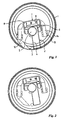
- the printing station shown in Fig. 1 comprises a stencil 1 with a squeegee device 2 arranged therein.
- the squeegee device 2 comprises, in the customary way, a squeegee element 3, a support profile 4 and a printing-medium feed 5.
- the squeegee device 2 is provided, on the top side, with a guide profile 6, along which a cleaning unit 7 can be displaced to and fro.
- the cleaning unit 7 comprises a trolley 8 which can roll along the guide profile 6 on running wheels 9. In this case, the running wheels 9 lie on either side of the squeegee device 2 and bear against the profile 6 both at the top and the bottom. Consequently, the position of the cleaning unit 7 with respect to the squeegee device 2 is accurately defined.
- the trolley 8 is provided with a tubular suction nozzle 10 which extends downwards inside the stencil 1.
- the suction nozzle 10 is intended to suck residual printing medium and/or cleaning liquid out of the stencil 1. This suction has to take place in particular during a cleaning operation, during which the stencil 1 and the squeegee device 2 are rinsed clean with the aid of cleaning liquid.
- the suction nozzle 10 opens out substantially at the lowest point in the stencil 1. As a result, it is possible to suck virtually all the liquids out of the bottom of the stencil 1.
- the squeegee device 2, together with the cleaning unit 7 which is guided over it, and the stencil 1, can be vertically adjusted with respect to one another.
- the suction nozzle 10 opens out substantially in the vicinity of the lowest point in the stencil 1.
- an at-rest position Fig. 2
- the squeegee device 2 together with cleaning unit 7 and suction nozzle 10 is clear of the stencil 1, so that the stencil 1, the squeegee device 2 and the cleaning unit 7 can be removed without damaging one another.
- the cleaning unit can be introduced both in the at-rest position and in the operating position of the squeegee device.
- a washing cycle consisting of feeding cleaning liquid and sucking out printing medium, may in principle be carried out both in the operating position and in the at-rest position.
- the suction nozzle may be provided at the end of a flexible hose. This provides the freedom to pass the cleaning unit through an end ring of the stencil, which end ring may have a passage which is smaller than the cleaning unit with flexible hose and suction nozzle.
- the suction nozzle 10 is provided on that side of the squeegee device 2 to which the printing medium is also fed through the printing-medium feed 5 and where the squeegee element 3 is located.
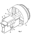
- suction nozzles 31 are positioned on both sides of a trolley 30.
- one or more suction nozzles are provided on the trolley only on that side of the squeegee device which lies opposite the squeegee element.
- the latter variant has the advantage that end partitions can be provided on the squeegee-element side of the squeegee device without these end partitions impeding the movements of the cleaning unit.
- cleaning liquid has to be fed to the stencil.
- This may, for example, be effected via a separate feed member which is introduced into the stencil, or via feed means which are integrated in the squeegee device.
- a plurality of spray heads 13 are provided on the cleaning unit 7. As can be seen from Figure 1, the spray heads 13 are directed both at the stencil 1 and at the squeegee device 2.
- the spray heads 13 are arranged at the ends of pipes 14 which are connected to the trolley 8.
- the feeding of cleaning liquid and the suction of residual printing medium mixed with the cleaning liquid may advantageously take place in a single displacement operation of the cleaning unit 7.
- the spray heads 13 may also be used to deliver air, by means of which the stencil 1 can be blown dry after a cleaning operation.
- the cleaning unit is provided with separate distributor heads for delivering air.
- the printing-medium feed 5 is integrated in the squeegee device 2.
- the printing-medium feed is also provided on the displaceable cleaning unit, so that it is possible to meter printing medium into the stencil during a traversing movement. This allows very accurate metering to be achieved.
- the cleaning unit may be fitted with a level detector for measuring the amount of printing medium during a printing process or the amount of cleaning liquid during a cleaning operation.
- the measurement data derived from the level detector can be used to control the displacement speed of the cleaning unit, the suction force from the suction installation and/or the pressure of the printing-medium feed.
- the displaceable cleaning unit may furthermore be provided with a homogenizer element, for example a stirrer blade which extends downwards in the stencil, for homogenizing, such as mixing, distributing or smoothing, of the printing medium in the stencil during or prior to a printing process.
- a homogenizer element for example a stirrer blade which extends downwards in the stencil, for homogenizing, such as mixing, distributing or smoothing, of the printing medium in the stencil during or prior to a printing process.
- the suction nozzle 10 which extends down to the bottom of the stencil 1 may also form the homogenizer element.
- the displaceable cleaning unit is fitted with a camera, by means of which the situation in the stencil can be monitored during a printing process.
- suction nozzles 31 are connected, at the rear side of the trolley 30, to a discharge hose 32 for discharging liquids which have been sucked in to outside the stencil 33.
- the discharge hose 32 is to be connected to a suction installation.
- the trolley also comprises a plurality of spray heads 34 which, at the rear side of the trolley 30, are connected to a feed hose 35 for feeding cleaning liquid.
- the feed hose 35 is to be connected to a cleaning-liquid reservoir.
- Fig. 4 shows a part of an embodiment of the screen-printing device according to the invention which lies at the side.
- Two adjacent printing stations each with a removable stencil 40 and a squeegee device 41 extending therein can be seen.
- the stencil 40 and the squeegee device 41 are vertically adjustable with respect to a substrate 42 which is to be printed and can be passed through beneath the printing stations.
- the stencil 40 is supported in a vertically adjustable stencil mount 43, while the squeegee device 41 is supported by a vertically adjustable squeegee suspension 44.
- the stencil 40 and the squeegee device 41 are shown in a raised at-rest position.
- the stencil 40 and the squeegee device 41 have been moved into a lowered printing position.
- a displaceable collecting shield 48 is provided, which can move between a parking position and a shielding position.
- the shielding position in which the collecting shield 48 is arranged between the stencil 40 and the substrate 42 which is to be printed, is shown in the left-hand printing station. In this shielding position, the stencil 40 and/or the squeegee device 41 can be cleaned at the printing station without there being any risk of contamination to the substrate 42 which is to be printed.
- the top side of the squeegee device 41 is provided with a guide profile 50, along which a displaceable cleaning unit 51 can be moved to and fro.
- a parking position for the cleaning unit 51 is provided to the side of each printing station.
- the parking position is formed by a separate guide rail 52.
- the guide profile 50 lies at the same height as the guide rail 52.
- the cleaning unit 51 can then be moved out of its parking position into the stencil.
- the parking position has the considerable advantage that the stencil 40 and the squeegee device 41 can be removed freely from the screen-printing device independently of the cleaning unit 51. It is also possible for the cleaning unit 51 to be cleaned thoroughly in its parking position outside the stencil 40.
- the guide rail 52 is fixed in position by a bent supporting bar 55 which is fixedly connected to the frame of the screen-printing device.
- the supporting bar 55 also forms a guide for feed and discharge hoses 56, 57 of the cleaning unit 51.
- the cleaning unit according to the invention can be driven manually or automatically in order to be displaced to and fro in the longitudinal direction inside the stencil.
- the automatic driving of the cleaning unit may be effected in many ways.
- the drive means are formed by the feed and/or discharge hoses of the cleaning unit.
- at least one of the hoses is rigid enough to enable the cleaning unit to be pushed forwards and pulled back by this hose.
- the hose may, for example, be driven by being clamped between two rollers, at least one of which is driven.
- Variants of the drive means may, for example, include pusher chains, rack-and-gear drives, spindle drives or piston-cylinder drives.
- the return movement of the cleaning unit may in all cases be provided by a spring or a weight attached to a separate cable.
- the discharge means arranged on the cleaning unit also comprise a scraper member.
- the scraper member may, for example, be formed by a plate which extends from the cleaning unit on one or both sides of the squeegee device and, while the cleaning unit is being moved inside the stencil, pushes printing medium and cleaning liquid in front of it.
- the suction nozzle can then advantageously suck out the residual printing medium and cleaning liquid which has been collected in front of the scraper member quickly and efficiently.
- the cleaning unit may be provided with delimiting means which delimit the stencil on one side. This may be advantageous in particular in the parking position of the cleaning unit, in which the delimiting means delimit one end of the stencil and prevent printing medium from leaking out of the stencil.
- the cleaning unit may, for example, be provided with a delimiting wall, which in turn may be formed by the abovementioned scraper member. It is also possible for the suction nozzle to be connected to an air feed and, in the parking position, to blow the printing medium back into the stencil.
- the invention provides a screen-printing device having a displaceable cleaning unit with which it is possible for stencils and squeegee devices at the printing stations to be cleaned thoroughly.
- the cleaning unit is also used for a number of other functions, such as for the controlled feed of cleaning liquid, the traversing metering of a printing medium and the monitoring of a printing process.
- the displaceable cleaning unit is not guided along the top side of a squeegee device, but rather a separate guide means, for example a guide rail, is provided, extending in the longitudinal direction inside the stencil.
- the separate guide means have the advantage that a cleaning operation on a stencil and removal and, if desired, replacement of a squeegee device can take place simultaneously.
- the cleaning unit may also comprise a carriage which can be slid along guide means.
- the cleaning unit and/or the suction nozzle may be designed in such a manner that they can be moved to and fro through the stencil not only in the axial direction but also in a direction which is transverse with respect to the latter.
- the residual printing medium can be recovered from the cleaning liquids which are sucked out.
- the displaceable cleaning unit can also be used for any other type of squeegee.
Landscapes
- Screen Printers (AREA)
- Inking, Control Or Cleaning Of Printing Machines (AREA)
- Electric Connection Of Electric Components To Printed Circuits (AREA)
- Coating Apparatus (AREA)
- Control And Other Processes For Unpacking Of Materials (AREA)
- External Artificial Organs (AREA)
- Medicines Containing Material From Animals Or Micro-Organisms (AREA)
- Application Of Or Painting With Fluid Materials (AREA)
- Manufacturing Of Printed Wiring (AREA)
Applications Claiming Priority (2)
| Application Number | Priority Date | Filing Date | Title |
|---|---|---|---|
| NL1011993 | 1999-05-07 | ||
| NL1011993A NL1011993C2 (nl) | 1999-05-07 | 1999-05-07 | Zeefdrukinrichting met een in een sjabloon verplaatsbare reinigingseenheid. |
Publications (2)
| Publication Number | Publication Date |
|---|---|
| EP1052096A1 EP1052096A1 (en) | 2000-11-15 |
| EP1052096B1 true EP1052096B1 (en) | 2004-10-06 |
Family
ID=19769149
Family Applications (2)
| Application Number | Title | Priority Date | Filing Date |
|---|---|---|---|
| EP00201589A Expired - Lifetime EP1052096B1 (en) | 1999-05-07 | 2000-05-02 | Screen-printing device with a cleaning unit which is displaceable inside a stencil |
| EP00927953A Expired - Lifetime EP1177099B1 (en) | 1999-05-07 | 2000-05-08 | Device for the dosing and distribution of hotmelt |
Family Applications After (1)
| Application Number | Title | Priority Date | Filing Date |
|---|---|---|---|
| EP00927953A Expired - Lifetime EP1177099B1 (en) | 1999-05-07 | 2000-05-08 | Device for the dosing and distribution of hotmelt |
Country Status (9)
| Country | Link |
|---|---|
| US (2) | US6619207B1 (enExample) |
| EP (2) | EP1052096B1 (enExample) |
| JP (1) | JP4787413B2 (enExample) |
| AT (2) | ATE278552T1 (enExample) |
| AU (1) | AU4625500A (enExample) |
| DE (2) | DE60014488T2 (enExample) |
| ES (2) | ES2225013T3 (enExample) |
| NL (1) | NL1011993C2 (enExample) |
| WO (1) | WO2000068011A1 (enExample) |
Families Citing this family (10)
| Publication number | Priority date | Publication date | Assignee | Title |
|---|---|---|---|---|
| US20020144610A1 (en) * | 2000-06-20 | 2002-10-10 | Peter Zimmer | Device and process for the removal of the screen coating from printing screens for silk screen printing |
| US7134389B2 (en) * | 2002-02-22 | 2006-11-14 | Minami Co., Ltd. | Screen printing apparatus |
| US20040238003A1 (en) * | 2003-05-30 | 2004-12-02 | Gerald Pham-Van-Diep | Stencil cleaner for use in the solder paste print operation |
| US9153341B2 (en) * | 2005-10-18 | 2015-10-06 | Semiconductor Energy Laboratory Co., Ltd. | Shift register, semiconductor device, display device, and electronic device |
| KR100953495B1 (ko) * | 2008-05-21 | 2010-04-16 | 건국대학교 산학협력단 | 롤투롤 방식 인쇄 방법 및 장치 |
| US8247827B2 (en) * | 2008-09-30 | 2012-08-21 | Bridgelux, Inc. | LED phosphor deposition |
| WO2015103030A1 (en) | 2013-12-31 | 2015-07-09 | Johnson & Johnson Consumer Companies, Inc. | Process for forming a multi layered shaped film |
| WO2015103034A1 (en) | 2013-12-31 | 2015-07-09 | Johnson & Johnson Consumer Companies, Inc. | Single-pass process for forming a multilayered shaped film product |
| EP3091969B1 (en) | 2013-12-31 | 2024-01-24 | Johnson & Johnson Consumer Inc. | Process for forming a shaped film product |
| KR101779411B1 (ko) | 2017-08-31 | 2017-09-18 | 인치영 | 스크린 인쇄 및 인쇄상태 확인을 연속적으로 수행하는 인쇄회로기판의 스크린 인쇄 시스템 |
Family Cites Families (15)
| Publication number | Priority date | Publication date | Assignee | Title |
|---|---|---|---|---|
| AT335961B (de) * | 1973-12-28 | 1977-04-12 | Zimmer Peter | Einrichtung zum reinigen einer siebdruckrotationsschablone |
| DE3034805A1 (de) * | 1980-09-16 | 1982-03-25 | Mathias 4815 Schloss Holte Mitter | Vorrichtung zur zufuehrung eines auftragsmediums vor eine auftragseinrichtung im inneren einer rotierenden bzw. auf einer ebenen schablone |
| JPS62132780U (enExample) * | 1986-02-13 | 1987-08-21 | ||
| US4622239A (en) * | 1986-02-18 | 1986-11-11 | At&T Technologies, Inc. | Method and apparatus for dispensing viscous materials |
| AT393246B (de) * | 1989-03-31 | 1991-09-10 | Hwb Maschinenbau | Auftragsvorrichtung zum aufbringen fliessfaehiger medien auf ebene flaechen, bahnen, walzen od. dgl. |
| BR9505844A (pt) * | 1994-02-12 | 1996-02-13 | Johannes Zimmer | Dispositivo autolimpante para a aplicação de uma substância sobre uma seção de têxtil |
| US5483884A (en) * | 1994-10-31 | 1996-01-16 | At&T Corp. | Method and apparatus for setting up a stencil printer |
| US5650009A (en) * | 1995-04-12 | 1997-07-22 | Nordson Corporation | Adustable rotary coater device for applying hot melt material to a moving web |
| US5584932A (en) * | 1995-04-12 | 1996-12-17 | Nordson Corporation | Electrical control circuit for controlling the speed and position of a rotary screen coater with respect to the line speed and position of a moving web |
| DE29517099U1 (de) * | 1995-10-17 | 1997-02-27 | Zimmer, Johannes, Klagenfurt | Auftragungsvorrichtung |
| NL1005308C2 (nl) | 1997-02-18 | 1998-08-20 | Stork Brabant Bv | Rakel met een vast dragend deel. |
| JPH10250044A (ja) * | 1997-03-18 | 1998-09-22 | Ichinose Internatl:Kk | ロータリスクリーン捺染機 |
| DE19736563C1 (de) * | 1997-08-22 | 1998-10-22 | Trans Textil Gmbh | Vorrichtung zum Auftragen von Schmelzkleber auf Bahnen |
| DE19806040A1 (de) * | 1998-02-13 | 1999-09-09 | Stork Mbk Gmbh | Vorrichtung und Verfahren zum Aufbringen eines Mediums auf ein Substrat und System mit mehreren solchen Vorrichtungen |
| US6145434A (en) * | 1998-03-20 | 2000-11-14 | Ricoh Company, Ltd. | Stencil printing method and device |
-
1999
- 1999-05-07 NL NL1011993A patent/NL1011993C2/nl not_active IP Right Cessation
-
2000
- 2000-05-02 ES ES00201589T patent/ES2225013T3/es not_active Expired - Lifetime
- 2000-05-02 AT AT00201589T patent/ATE278552T1/de active
- 2000-05-02 EP EP00201589A patent/EP1052096B1/en not_active Expired - Lifetime
- 2000-05-02 DE DE60014488T patent/DE60014488T2/de not_active Expired - Lifetime
- 2000-05-05 US US09/566,280 patent/US6619207B1/en not_active Expired - Fee Related
- 2000-05-08 WO PCT/NL2000/000292 patent/WO2000068011A1/en not_active Ceased
- 2000-05-08 ES ES00927953T patent/ES2204591T3/es not_active Expired - Lifetime
- 2000-05-08 JP JP2000617019A patent/JP4787413B2/ja not_active Expired - Fee Related
- 2000-05-08 AT AT00927953T patent/ATE247561T1/de not_active IP Right Cessation
- 2000-05-08 AU AU46255/00A patent/AU4625500A/en not_active Abandoned
- 2000-05-08 EP EP00927953A patent/EP1177099B1/en not_active Expired - Lifetime
- 2000-05-08 DE DE60004659T patent/DE60004659T2/de not_active Expired - Lifetime
-
2001
- 2001-10-29 US US10/021,418 patent/US6656274B2/en not_active Expired - Fee Related
Also Published As
| Publication number | Publication date |
|---|---|
| ATE247561T1 (de) | 2003-09-15 |
| DE60004659T2 (de) | 2004-06-17 |
| ATE278552T1 (de) | 2004-10-15 |
| NL1011993C2 (nl) | 2000-11-09 |
| ES2225013T3 (es) | 2005-03-16 |
| DE60014488T2 (de) | 2005-05-19 |
| EP1177099A1 (en) | 2002-02-06 |
| EP1177099B1 (en) | 2003-08-20 |
| JP2002544009A (ja) | 2002-12-24 |
| WO2000068011A1 (en) | 2000-11-16 |
| US6619207B1 (en) | 2003-09-16 |
| JP4787413B2 (ja) | 2011-10-05 |
| ES2204591T3 (es) | 2004-05-01 |
| EP1052096A1 (en) | 2000-11-15 |
| DE60014488D1 (de) | 2004-11-11 |
| DE60004659D1 (de) | 2003-09-25 |
| US6656274B2 (en) | 2003-12-02 |
| AU4625500A (en) | 2000-11-21 |
| US20020076496A1 (en) | 2002-06-20 |
Similar Documents
| Publication | Publication Date | Title |
|---|---|---|
| EP1052096B1 (en) | Screen-printing device with a cleaning unit which is displaceable inside a stencil | |
| US4393778A (en) | Device for washing blanket cylinder of rotary offset press | |
| JP2007503342A (ja) | 三次元プリント装置及び方法 | |
| EP3260031A1 (de) | Vorrichtung zur reinigung von scheuersaugmaschinen | |
| EP0918642B1 (en) | Method and apparatus for cleaning flexographic printing plates | |
| JP5092645B2 (ja) | 液体噴射装置 | |
| EP3853027A1 (en) | Printing apparatus with multi-head cleaning of inkjet printface and method of cleaning thereof | |
| CN114950809B (zh) | 喷嘴清洗装置、喷嘴清洗方法以及涂布装置 | |
| US5769956A (en) | Method for cleaning a screen by spraying and moving in a repeated continuous oscillating motion | |
| JP5076766B2 (ja) | 液体噴射装置 | |
| JP7311716B2 (ja) | 印刷機械、および少なくとも1つの印刷モジュールの少なくとも1つのノズルバーをクリーニングする方法 | |
| US4448152A (en) | Apparatus for rearing small animals | |
| EP3103643A1 (en) | Ink jet printer with maintenance unit | |
| DE19816660A1 (de) | Farbwerk für Rotationsdruckmaschinen | |
| US6101936A (en) | Squeegee with a fixed supporting part | |
| US5775218A (en) | Self-cleaning apparatus for the application of a substance on a fabric train and process of operation thereof | |
| EP0993949B1 (en) | Screen-printing device with printing-station shield | |
| WO1996024492A1 (en) | Oscillator screen cleaning apparatus | |
| CN108290550B (zh) | 车辆清洗设备 | |
| CN220447439U (zh) | 用于批量印刷的丝印装置 | |
| JP2022540481A (ja) | プレート状の印刷媒体に印刷するプリンタ、プリンタ用の清掃装置およびプリンタを保守する方法 | |
| JP2657826B2 (ja) | 印刷機のローラ洗浄装置 | |
| DE20308645U1 (de) | Reinigungsvorrichtung für das Druckwerk einer Rotationsdruckmaschine | |
| JP2009078397A (ja) | プリンター装置 | |
| WO2001015813A2 (de) | Vorrichtung zur entnahme eines pulverartigen haufwerks und zu dessen weiterführung sowie verfahren zu ihrer reinigung |
Legal Events
| Date | Code | Title | Description |
|---|---|---|---|
| PUAI | Public reference made under article 153(3) epc to a published international application that has entered the european phase |
Free format text: ORIGINAL CODE: 0009012 |
|
| AK | Designated contracting states |
Kind code of ref document: A1 Designated state(s): AT BE CH CY DE DK ES FI FR GB GR IE IT LI LU MC NL PT SE |
|
| AX | Request for extension of the european patent |
Free format text: AL;LT;LV;MK;RO;SI |
|
| 17P | Request for examination filed |
Effective date: 20010412 |
|
| AKX | Designation fees paid |
Free format text: AT BE CH CY DE DK ES FI FR GB GR IE IT LI LU MC NL PT SE |
|
| RAP1 | Party data changed (applicant data changed or rights of an application transferred) |
Owner name: STORK PRINTS B.V. |
|
| GRAP | Despatch of communication of intention to grant a patent |
Free format text: ORIGINAL CODE: EPIDOSNIGR1 |
|
| GRAS | Grant fee paid |
Free format text: ORIGINAL CODE: EPIDOSNIGR3 |
|
| GRAA | (expected) grant |
Free format text: ORIGINAL CODE: 0009210 |
|
| AK | Designated contracting states |
Kind code of ref document: B1 Designated state(s): AT BE CH CY DE DK ES FI FR GB GR IE IT LI LU MC NL PT SE |
|
| PG25 | Lapsed in a contracting state [announced via postgrant information from national office to epo] |
Ref country code: CH Free format text: LAPSE BECAUSE OF FAILURE TO SUBMIT A TRANSLATION OF THE DESCRIPTION OR TO PAY THE FEE WITHIN THE PRESCRIBED TIME-LIMIT Effective date: 20041006 Ref country code: FI Free format text: LAPSE BECAUSE OF FAILURE TO SUBMIT A TRANSLATION OF THE DESCRIPTION OR TO PAY THE FEE WITHIN THE PRESCRIBED TIME-LIMIT Effective date: 20041006 Ref country code: LI Free format text: LAPSE BECAUSE OF FAILURE TO SUBMIT A TRANSLATION OF THE DESCRIPTION OR TO PAY THE FEE WITHIN THE PRESCRIBED TIME-LIMIT Effective date: 20041006 Ref country code: BE Free format text: LAPSE BECAUSE OF FAILURE TO SUBMIT A TRANSLATION OF THE DESCRIPTION OR TO PAY THE FEE WITHIN THE PRESCRIBED TIME-LIMIT Effective date: 20041006 |
|
| REG | Reference to a national code |
Ref country code: GB Ref legal event code: FG4D |
|
| REG | Reference to a national code |
Ref country code: CH Ref legal event code: EP |
|
| REG | Reference to a national code |
Ref country code: IE Ref legal event code: FG4D |
|
| REF | Corresponds to: |
Ref document number: 60014488 Country of ref document: DE Date of ref document: 20041111 Kind code of ref document: P |
|
| PG25 | Lapsed in a contracting state [announced via postgrant information from national office to epo] |
Ref country code: DK Free format text: LAPSE BECAUSE OF FAILURE TO SUBMIT A TRANSLATION OF THE DESCRIPTION OR TO PAY THE FEE WITHIN THE PRESCRIBED TIME-LIMIT Effective date: 20050106 Ref country code: GR Free format text: LAPSE BECAUSE OF FAILURE TO SUBMIT A TRANSLATION OF THE DESCRIPTION OR TO PAY THE FEE WITHIN THE PRESCRIBED TIME-LIMIT Effective date: 20050106 Ref country code: SE Free format text: LAPSE BECAUSE OF FAILURE TO SUBMIT A TRANSLATION OF THE DESCRIPTION OR TO PAY THE FEE WITHIN THE PRESCRIBED TIME-LIMIT Effective date: 20050106 |
|
| REG | Reference to a national code |
Ref country code: ES Ref legal event code: FG2A Ref document number: 2225013 Country of ref document: ES Kind code of ref document: T3 |
|
| REG | Reference to a national code |
Ref country code: CH Ref legal event code: PL |
|
| PG25 | Lapsed in a contracting state [announced via postgrant information from national office to epo] |
Ref country code: LU Free format text: LAPSE BECAUSE OF NON-PAYMENT OF DUE FEES Effective date: 20050502 Ref country code: IE Free format text: LAPSE BECAUSE OF NON-PAYMENT OF DUE FEES Effective date: 20050502 Ref country code: GB Free format text: LAPSE BECAUSE OF NON-PAYMENT OF DUE FEES Effective date: 20050502 Ref country code: CY Free format text: LAPSE BECAUSE OF FAILURE TO SUBMIT A TRANSLATION OF THE DESCRIPTION OR TO PAY THE FEE WITHIN THE PRESCRIBED TIME-LIMIT Effective date: 20050502 |
|
| ET | Fr: translation filed | ||
| PG25 | Lapsed in a contracting state [announced via postgrant information from national office to epo] |
Ref country code: MC Free format text: LAPSE BECAUSE OF NON-PAYMENT OF DUE FEES Effective date: 20050531 |
|
| PLBE | No opposition filed within time limit |
Free format text: ORIGINAL CODE: 0009261 |
|
| STAA | Information on the status of an ep patent application or granted ep patent |
Free format text: STATUS: NO OPPOSITION FILED WITHIN TIME LIMIT |
|
| 26N | No opposition filed |
Effective date: 20050707 |
|
| GBPC | Gb: european patent ceased through non-payment of renewal fee |
Effective date: 20050502 |
|
| REG | Reference to a national code |
Ref country code: IE Ref legal event code: MM4A |
|
| PG25 | Lapsed in a contracting state [announced via postgrant information from national office to epo] |
Ref country code: PT Free format text: LAPSE BECAUSE OF NON-PAYMENT OF DUE FEES Effective date: 20050306 |
|
| REG | Reference to a national code |
Ref country code: FR Ref legal event code: PLFP Year of fee payment: 17 |
|
| REG | Reference to a national code |
Ref country code: FR Ref legal event code: PLFP Year of fee payment: 18 |
|
| REG | Reference to a national code |
Ref country code: NL Ref legal event code: HC Owner name: SPGPRINTS B.V.; NL Free format text: DETAILS ASSIGNMENT: CHANGE OF OWNER(S), CHANGE OF OWNER(S) NAME; FORMER OWNER NAME: STORK PRINTS B.V. Effective date: 20171214 Ref country code: NL Ref legal event code: RC Free format text: DETAILS LICENCE OR PLEDGE: RIGHT OF PLEDGE, ESTABLISHED Name of requester: LLOYDS BANK PLC Effective date: 20171214 |
|
| REG | Reference to a national code |
Ref country code: FR Ref legal event code: PLFP Year of fee payment: 19 |
|
| PGFP | Annual fee paid to national office [announced via postgrant information from national office to epo] |
Ref country code: DE Payment date: 20180522 Year of fee payment: 19 |
|
| PGFP | Annual fee paid to national office [announced via postgrant information from national office to epo] |
Ref country code: NL Payment date: 20180523 Year of fee payment: 19 |
|
| PGFP | Annual fee paid to national office [announced via postgrant information from national office to epo] |
Ref country code: IT Payment date: 20190530 Year of fee payment: 20 |
|
| PGFP | Annual fee paid to national office [announced via postgrant information from national office to epo] |
Ref country code: AT Payment date: 20190523 Year of fee payment: 20 Ref country code: ES Payment date: 20190821 Year of fee payment: 20 |
|
| REG | Reference to a national code |
Ref country code: DE Ref legal event code: R119 Ref document number: 60014488 Country of ref document: DE |
|
| REG | Reference to a national code |
Ref country code: NL Ref legal event code: MM Effective date: 20190601 |
|
| PG25 | Lapsed in a contracting state [announced via postgrant information from national office to epo] |
Ref country code: NL Free format text: LAPSE BECAUSE OF NON-PAYMENT OF DUE FEES Effective date: 20190601 Ref country code: DE Free format text: LAPSE BECAUSE OF NON-PAYMENT OF DUE FEES Effective date: 20191203 |
|
| PG25 | Lapsed in a contracting state [announced via postgrant information from national office to epo] |
Ref country code: FR Free format text: LAPSE BECAUSE OF NON-PAYMENT OF DUE FEES Effective date: 20190531 |
|
| REG | Reference to a national code |
Ref country code: AT Ref legal event code: MK07 Ref document number: 278552 Country of ref document: AT Kind code of ref document: T Effective date: 20200502 |
|
| REG | Reference to a national code |
Ref country code: ES Ref legal event code: FD2A Effective date: 20220128 |
|
| PG25 | Lapsed in a contracting state [announced via postgrant information from national office to epo] |
Ref country code: ES Free format text: LAPSE BECAUSE OF EXPIRATION OF PROTECTION Effective date: 20200503 |