EP1051990A1 - Sonde a ballonnet, tige de sonde associee et procede de production de ballonnet - Google Patents
Sonde a ballonnet, tige de sonde associee et procede de production de ballonnet Download PDFInfo
- Publication number
- EP1051990A1 EP1051990A1 EP98945628A EP98945628A EP1051990A1 EP 1051990 A1 EP1051990 A1 EP 1051990A1 EP 98945628 A EP98945628 A EP 98945628A EP 98945628 A EP98945628 A EP 98945628A EP 1051990 A1 EP1051990 A1 EP 1051990A1
- Authority
- EP
- European Patent Office
- Prior art keywords
- lumen
- shaft
- balloon
- tube
- catheter
- Prior art date
- Legal status (The legal status is an assumption and is not a legal conclusion. Google has not performed a legal analysis and makes no representation as to the accuracy of the status listed.)
- Granted
Links
Images


Classifications
-
- A—HUMAN NECESSITIES
- A61—MEDICAL OR VETERINARY SCIENCE; HYGIENE
- A61M—DEVICES FOR INTRODUCING MEDIA INTO, OR ONTO, THE BODY; DEVICES FOR TRANSDUCING BODY MEDIA OR FOR TAKING MEDIA FROM THE BODY; DEVICES FOR PRODUCING OR ENDING SLEEP OR STUPOR
- A61M25/00—Catheters; Hollow probes
- A61M25/10—Balloon catheters
- A61M25/1027—Making of balloon catheters
- A61M25/1029—Production methods of the balloon members, e.g. blow-moulding, extruding, deposition or by wrapping a plurality of layers of balloon material around a mandril
-
- A—HUMAN NECESSITIES
- A61—MEDICAL OR VETERINARY SCIENCE; HYGIENE
- A61M—DEVICES FOR INTRODUCING MEDIA INTO, OR ONTO, THE BODY; DEVICES FOR TRANSDUCING BODY MEDIA OR FOR TAKING MEDIA FROM THE BODY; DEVICES FOR PRODUCING OR ENDING SLEEP OR STUPOR
- A61M25/00—Catheters; Hollow probes
- A61M25/10—Balloon catheters
- A61M25/1027—Making of balloon catheters
- A61M25/1036—Making parts for balloon catheter systems, e.g. shafts or distal ends
-
- A—HUMAN NECESSITIES
- A61—MEDICAL OR VETERINARY SCIENCE; HYGIENE
- A61M—DEVICES FOR INTRODUCING MEDIA INTO, OR ONTO, THE BODY; DEVICES FOR TRANSDUCING BODY MEDIA OR FOR TAKING MEDIA FROM THE BODY; DEVICES FOR PRODUCING OR ENDING SLEEP OR STUPOR
- A61M25/00—Catheters; Hollow probes
- A61M25/0021—Catheters; Hollow probes characterised by the form of the tubing
- A61M25/0023—Catheters; Hollow probes characterised by the form of the tubing by the form of the lumen, e.g. cross-section, variable diameter
- A61M25/0026—Multi-lumen catheters with stationary elements
- A61M2025/0034—Multi-lumen catheters with stationary elements characterized by elements which are assembled, connected or fused, e.g. splittable tubes, outer sheaths creating lumina or separate cores
-
- A—HUMAN NECESSITIES
- A61—MEDICAL OR VETERINARY SCIENCE; HYGIENE
- A61M—DEVICES FOR INTRODUCING MEDIA INTO, OR ONTO, THE BODY; DEVICES FOR TRANSDUCING BODY MEDIA OR FOR TAKING MEDIA FROM THE BODY; DEVICES FOR PRODUCING OR ENDING SLEEP OR STUPOR
- A61M25/00—Catheters; Hollow probes
- A61M25/0043—Catheters; Hollow probes characterised by structural features
- A61M25/0045—Catheters; Hollow probes characterised by structural features multi-layered, e.g. coated
- A61M2025/0046—Coatings for improving slidability
- A61M2025/0047—Coatings for improving slidability the inner layer having a higher lubricity
-
- A—HUMAN NECESSITIES
- A61—MEDICAL OR VETERINARY SCIENCE; HYGIENE
- A61M—DEVICES FOR INTRODUCING MEDIA INTO, OR ONTO, THE BODY; DEVICES FOR TRANSDUCING BODY MEDIA OR FOR TAKING MEDIA FROM THE BODY; DEVICES FOR PRODUCING OR ENDING SLEEP OR STUPOR
- A61M25/00—Catheters; Hollow probes
- A61M25/0043—Catheters; Hollow probes characterised by structural features
- A61M2025/0063—Catheters; Hollow probes characterised by structural features having means, e.g. stylets, mandrils, rods or wires to reinforce or adjust temporarily the stiffness, column strength or pushability of catheters which are already inserted into the human body
-
- A—HUMAN NECESSITIES
- A61—MEDICAL OR VETERINARY SCIENCE; HYGIENE
- A61M—DEVICES FOR INTRODUCING MEDIA INTO, OR ONTO, THE BODY; DEVICES FOR TRANSDUCING BODY MEDIA OR FOR TAKING MEDIA FROM THE BODY; DEVICES FOR PRODUCING OR ENDING SLEEP OR STUPOR
- A61M25/00—Catheters; Hollow probes
- A61M25/01—Introducing, guiding, advancing, emplacing or holding catheters
- A61M2025/0183—Rapid exchange or monorail catheters
-
- A—HUMAN NECESSITIES
- A61—MEDICAL OR VETERINARY SCIENCE; HYGIENE
- A61M—DEVICES FOR INTRODUCING MEDIA INTO, OR ONTO, THE BODY; DEVICES FOR TRANSDUCING BODY MEDIA OR FOR TAKING MEDIA FROM THE BODY; DEVICES FOR PRODUCING OR ENDING SLEEP OR STUPOR
- A61M25/00—Catheters; Hollow probes
- A61M25/10—Balloon catheters
- A61M2025/1043—Balloon catheters with special features or adapted for special applications
- A61M2025/1054—Balloon catheters with special features or adapted for special applications having detachable or disposable balloons
-
- A—HUMAN NECESSITIES
- A61—MEDICAL OR VETERINARY SCIENCE; HYGIENE
- A61M—DEVICES FOR INTRODUCING MEDIA INTO, OR ONTO, THE BODY; DEVICES FOR TRANSDUCING BODY MEDIA OR FOR TAKING MEDIA FROM THE BODY; DEVICES FOR PRODUCING OR ENDING SLEEP OR STUPOR
- A61M25/00—Catheters; Hollow probes
- A61M25/0021—Catheters; Hollow probes characterised by the form of the tubing
- A61M25/0023—Catheters; Hollow probes characterised by the form of the tubing by the form of the lumen, e.g. cross-section, variable diameter
- A61M25/0026—Multi-lumen catheters with stationary elements
- A61M25/0029—Multi-lumen catheters with stationary elements characterized by features relating to least one lumen located at the middle part of the catheter, e.g. slots, flaps, valves, cuffs, apertures, notches, grooves or rapid exchange ports
-
- A—HUMAN NECESSITIES
- A61—MEDICAL OR VETERINARY SCIENCE; HYGIENE
- A61M—DEVICES FOR INTRODUCING MEDIA INTO, OR ONTO, THE BODY; DEVICES FOR TRANSDUCING BODY MEDIA OR FOR TAKING MEDIA FROM THE BODY; DEVICES FOR PRODUCING OR ENDING SLEEP OR STUPOR
- A61M25/00—Catheters; Hollow probes
- A61M25/0021—Catheters; Hollow probes characterised by the form of the tubing
- A61M25/0023—Catheters; Hollow probes characterised by the form of the tubing by the form of the lumen, e.g. cross-section, variable diameter
- A61M25/0026—Multi-lumen catheters with stationary elements
- A61M25/0032—Multi-lumen catheters with stationary elements characterized by at least one unconventionally shaped lumen, e.g. polygons, ellipsoids, wedges or shapes comprising concave and convex parts
Definitions
- This invention relates to a balloon catheter and to a method for manufacturing a catheter shaft and balloon used therein, and more particularly relates to a balloon.
- PTA percutaneous transluminal angioplasty
- PTCA percutaneous transluminal coronary angioplasty
- a balloon catheter is primarily made up of a catheter shaft and a vascular dilation balloon provided to the distal end portion of this catheter shaft. At least two lumens (cavities) are formed in the interior of the catheter shaft. One of these is a guide wire lumen through which a guide wire is passed, and the second is an inflation lumen through which a pressure fluid such as a contrast medium or physiological saline is passed in order to inflate or deflate the balloon.
- Angioplasty using a balloon catheter such as this is conducted by the following procedure.
- a guide catheter is inserted through the femoral artery and positioned at the far end of the inlet to the coronary artery, after which a guide wire that goes through the balloon catheter is advanced past a constricted site in the coronary artery, then the balloon catheter is advanced along the guide wire and inflated when the balloon is located at the constriction. After the constriction has been dilated, the balloon is deflated and taken out of the body.
- a balloon catheter such as this is not limited to the treatment of arterial constrictions, and can be used in many other medical applications, including insertion into blood vessels and insertion into various bodily cavities.
- a catheter shaft Some of the characteristics required of a catheter shaft are its pushability, which is a measure of how efficiently the pushing force applied to the proximal end is transmitted to the distal end, the flexibility of the portion 20 to 30 cm from its distal end, that is, its trackability, which allows this portion to proceed smoothly through curved blood vessels, and its diameter, which needs to be small enough to allow insertion into narrow blood vessels. Since the balloon provided at the distal end is inflated or deflated by introducing a pressure fluid into the inflation lumen, the catheter shaft must be strong enough to withstand the pressure from this pressure fluid.
- the modulus of elasticity of the catheter shaft needs to be raised in order to raise this pressure resistance strength and improve the pushability, while the modulus of elasticity of the catheter shaft needs to be lowered in order to improve trackability.
- the balloon catheters in use today can be divided into over-the-wire balloon types and monorail types.
- An over-the-wire balloon catheter has a structure in which the guide wire lumen extends the entire length of the catheter, from the farthest end to the nearest end of the catheter.
- Monorail types are discussed in detail in U.S. Patents 4,762,129 and 4,748982, in which the lumen used for guide wire passage is formed only in the distal portion of the catheter, and the guide wire exits the catheter on the proximal side of this distal portion.
- the most salient feature of an over-the-wire balloon catheter is that because the guide wire passes through the interior of the catheter over the entire length of the catheter, there is no slackening of the guide wire and good pushability is obtained even if an obstacle is encountered that would hinder the advance of the guide wire at the catheter distal end portion. As a result, a back-up force can be imparted to the guide wire, making it possible for the guide wire to pass more easily through highly constricted afflicted sites.
- the balloon catheter has to be replaced for a reason such as the inability to obtain the desired inflation diameter, if a guide wire of ordinary length is being used, an extension guide wire will have to be used, so replacing the balloon catheter takes more time and trouble.
- a monorail type of balloon catheter in regard to this point is that although the pushability is not as good, there is no need to use an extension guide wire, so the balloon catheter can be replaced more easily and quickly. This shortens the time required to perform PTCA, and allows PTCA to be performed more times per day. Furthermore, a monorail type of balloon catheter is advantageous because the number of catheters needed for treatment can be kept low and the cost of the PTCA kept down, and because cases involving the use of a stent are on the rise in recent years.
- guide wire lubricity the efficient transmission to the distal end of the pushing force applied to the proximal end of the catheter shaft
- trackability the ability to advance smoothly along a curved blood vessel
- a small diameter small diameter
- the first invention is a balloon catheter having a catheter shaft comprising a multi-lumen tube inclusive of a dual-lumen tube, and a balloon provided to the distal end of the catheter shaft, wherein the multi-lumen tube is equipped with at least a guide wire lumen and an inflation lumen, and is composed of a resin material having a flexural modulus that contributes to pushability and trackability, and a resin material layer having a lubricity higher than that of the constituent material of the guide wire lumen and having a surface energy of no more than 50 dyn/cm is present on the inner surface of the guide wire lumen.
- the second invention is such that a tube composed of a highly elastic resin material having an elastic modulus higher than that of the constituent material of the inflation lumen and having a surface energy of no more than 50 dyn/cm is present in the interior of the inflation lumen.
- the third invention is such that the outer surface of the multi-lumen tube is covered with a highly elastic resin material having an elastic modulus higher than that of the multi-lumen tube.
- the resin material layer present on the inner surface of the guide wire lumen is formed from a tube composed of a fluororesin material or a polyolefin-based resin material inclusive of polyethylene, or is a coating layer composed of a fluororesin material.
- the multi-lumen tube is composed of a resin material having a flexural modulus of at least 2000 kgf/cm 2 and no more than 10,000 kgf/cm 2 , or more specifically, composed of a resin material selected from among nylon, polyamide-based elastomers, polyesters, polyester-based elastomers, polyurethane-based elastomers, polyolefins, polyimides, polyimidoamides, and polyether imides.
- At least the distal portion of the catheter shaft may be made from a resin material and have the above-mentioned catheter shaft structure.
- the proximal portion of the catheter shaft may have a different constitution from the above-mentioned catheter shaft structure and resin material.
- the highly elastic resin material of the tube provided in the interior of the inflation lumen in the second invention, or the highly elastic resin material covering the outer surface of the multi-lumen tube in the third invention is a resin material with a tensile modulus of at least 1 GPa (10 9 Pascal), with the use of a resin material composed of a polyimide being particularly favorable.
- the fourth and fifth inventions discussed below are methods for manufacturing the catheter shaft of the above-mentioned balloon catheter.
- the fourth invention is a method for manufacturing a catheter shaft, in which a tube composed of a resin material different from the resin material of which the multi-lumen tube is composed is fixed to at least one lumen out of the multi-lumen tube, wherein a multi-lumen tube having a lumen with an inside diameter that is larger than the outside diameter of this tube of a different material is prepared in advance, and the tube of a different material is inserted into the lumen in a state in which a mandrel for maintaining the inside diameter has been fitted into the center of this tube, then the multi-lumen tube is stretched by applying heat from the outside in a state in which a tensile force is applied to the multi-lumen tube in the axial direction, and the tube of a different material is fixed inside the multi-lumen tube.
- this mandrel is cooled with air or a liquid.
- the fifth invention is a method for manufacturing a catheter shaft for a balloon catheter, in which a tube composed of a resin material different from the resin material of which the multi-lumen tube is composed is fixed to at least one lumen out of the multi-lumen tube, wherein a tube composed of a different resin material and having an outside diameter that is substantially equal to or larger than the inside diameter of the lumen is prepared in advance, the tube is passed through a mold with a specific outside diameter while heat is applied from the outside, thereby forming the outside diameter of the tube to high precision, and the tube is then inserted into the lumen, one or both ends of the lumen in its axial direction are fixed to the outer peripheral surface of the tube with an adhesive agent, and the tube is fixed inside the multi-lumen tube.
- the tube is passed through a mold with a specific outside diameter while heat is applied from the outside in a state in which a mandrel for maintaining the inside diameter has been inserted into the center of the tube.
- the mold is equipped with means for blowing hot air at the tube, and it is preferable for a UV curing type, urethane-based, or cyanoacrylate-based adhesive agent to be used as the adhesive agent.
- the sixth invention is a balloon catheter with a balloon provided to the distal end of a catheter shaft, in which at least the distal portion of the catheter shaft is composed of a resin material having a flexural modulus that contributes to pushability and trackability, wherein the balloon is composed of a thermoplastic elastomer with a tensile strength of at least 300 kgf/cm 2 (by the method in ASTM-D638), an elongation of no more than 600% (by the method in ASTM-D638), and a Shore hardness of at least 50D (D scale), and the soft segment of the thermoplastic elastomer includes a polyester component.
- the balloon has a rated bursting pressure of at least 12 atm and no more than 18 atm when its inflated outside diameter is 3.5 mm or less and its wall thickness is no more than 20 ⁇ m. It is also preferable if the main component of the hard segment of the thermoplastic elastomer is one or more types selected from the group consisting of polyesters, polyamides, and polyurethanes.
- the flexural modulus is at least 2000 kgf/cm 2 and no more than 10,000 kgf /cm 2 .
- the balloon catheter pertaining to the present invention may combine a catheter shaft pertaining to one of the above first to third inventions with a balloon pertaining to the above sixth invention.
- the method for manufacturing the above balloon involves the use of a thermoplastic elastomer containing a soft segment whose main component is polyester and which has a tensile strength of at least 300 kgf/cm 2 (by the method in ASTM-D638), an elongation of no more than 600%(by the method in ASTM-D638), and a Shore hardness of at least 50D (D scale), and comprises a first stretching step in which a balloon parison is axially stretched at least two times its length in an environment between room temperature and up to 80% of the thermal deformation temperature of said thermoplastic elastomer, and a second stretching step in which the balloon parison is radially stretched in a plurality of stages by a pressurized gas or liquid, with the elongation per stage adjusted to within a range of at least 1.2 times and no more than 2.5 times.
- the balloon has a rated bursting pressure of at least 12 atm and no more than 18 atm when its inflated outside diameter is 3.5 mm or less and its wall thickness is no more than 20 ⁇ m. It is also preferable if the main component of the hard segment of the thermoplastic elastomer is one or more types selected from the group consisting of polyesters, polyamides, and polyurethanes.
- a monorail type balloon catheter is such that the above-mentioned catheter shaft comprises a distal shaft provided with a balloon at its distal end portion, and a proximal shaft composed of a miscible resin material that has substantially the same melting point as said distal shaft, the distal end portion of the proximal shaft and the proximal end portion of the distal shaft are joined using a joining member composed of the same resin material as the proximal shaft or of a miscible resin material that has substantially the same melting point as the proximal shaft, and a guide wire inlet that communicates with the guide wire lumen is formed in the proximity of this joint.
- the joining member is a cylindrical or ribbon-shaped member having an inside diameter that is larger than the outside diameter of the catheter shaft.
- the proximal shaft comprises a first proximal shaft that is joined to the distal shaft, and a second proximal shaft that is located closer to the proximal side than the first proximal shaft; has a greater overall length and a higher rigidity than the first proximal shaft, and is composed of a resin, a metal, or both.
- the method for manufacturing this monorail type balloon catheter is such that the proximal end portion of a distal shaft provided with a balloon at its distal end portion is brought into contact with the distal end portion of a proximal shaft composed of a miscible resin material that has substantially the same melting point as the distal shaft, a joining member composed of the same resin material as the proximal shaft or of a miscible resin material that has substantially the same melting point as the proximal shaft is disposed at this contact portion, the joining member is thermally deformed to join the proximal shaft to the distal shaft, and a guide wire inlet that communicates with the guide wire lumen of the distal shaft is formed in the proximity of this joint.
- the joining member is a cylindrical or ribbon-shaped member having an inside diameter that is larger than the outside diameter of the catheter shaft.
- the joining member is covered with a heat-shrink tube, and the heat-shrink tube is heated to thermally deform the joining member.
- Another method that can be used is such that the above heat-shrink tube is not used, and the entire periphery of the joining member is covered with a heating mold, and the joining member is heated and thermally deformed by the heating mold.
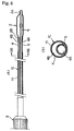
- Figure 1 is an overall side view of the over- the-wire type of balloon catheter pertaining to the present invention.
- 1 is a shaft
- 2 is a balloon provided to the distal end portion of the shaft
- 3 is a manifold provided to the proximal end of the shaft 1.
- the balloon 2 and manifold 3 here have conventional structures.
- the shaft 1 is equipped with at least a guide wire lumen through which is passed a guide wire (not shown) for guiding the balloon catheter to a specific afflicted site, and an inflation lumen through which is introduced a pressure fluid for inflating or deflating the balloon 2.
- the manifold 3 is provided with ports 3A and 3B communicating with these lumens.
- the shaft 1 is inclusive of a dual-lumen tube having in its interior a guide wire lumen and an inflation lumen, but the present invention can also be expanded to a multi-lumen tube in which lumens for other purposes are laid out next to the above two lumens.
- Figures 2 (a) and (b) illustrate an embodiment of the over-the-wire balloon catheter pertaining to the first invention.
- Figure 2 (b) is a cross section along the X1-X1 line in (a).
- a multi-lumen shaft 1A pertaining to the present invention is provided over the entire length of the catheter.
- the basic structure of the shaft 1A comprises a multi-lumen tube 4 extrusion-molded from a resin material having a flexural modulus within a range that contributes to pushability and trackability.
- a mono- (or single-) lumen tube 5 composed of a different resin material with a high lubricity and having a circular cross sectional shape (hereinafter referred to simply as "tube 5").
- the multi-lumen tube 4 is made from a resin material with a flexural modulus of at least 2000 kgf/cm 2 and no more than 10,000 kgf/cm 2 . More specifically, it is made from a resin material selected from among nylon, polyamide-based elastomers, polyesters, polyester-based elastomers, polyurethane-based elastomers, polyolefins, polyimides, polyimidoamides, and polyether imides.
- the tube 5 is made from a resin material that has high lubricity with respect to the guide wire and has a surface energy of no more than 50 dyn/cm. More specifically, it is made from a fluororesin material or a polyolefin-based resin material inclusive of polyethylene.
- the cross sectional shape of this multi-lumen tube 4 is as shown in Figure 2 (b).
- the cross sectional shape of the guide wire lumen 4A is circular.
- the cross section of the inflation lumen 4B is C-shaped, and the line S1 that connects the ends 4a and 4b of this C-shaped cross section is located on the guide wire lumen 4A side of the tangent T1 to the peripheral section of the circular lumen 4A closest to the C-shaped lumen 4B.
- a resin layer 4C that forms the tube 4 is present at the boundary between the guide wire lumen 4A and the inflation lumen 4B.
- the cross sectional shape of the inflation lumen 4B is C-shaped is that this ensures the largest possible cross sectional area for the inflation lumen 4B in the portion other than the guide wire lumen 4A, which facilitates the flow of the pressure fluid through this lumen, that is, it maximizes conductance and minimizes the time it takes to inflate or deflate the balloon 2. If the time it takes to inflate or deflate the balloon 2 is shortened, this reduces the time required for dilation of a constriction in a blood vessel, or to put it another way, shortens the time that the blood vessel is blocked by the inflated balloon 2, which is advantageous in that it reduces the burden on the patient.
- the distal end of the tube 5 is made to extend a specific length beyond the distal end of the multi-lumen tube 4, the distal end portion 2A of the balloon, which is in the form of a wrappable and inflatable tube, is fastened airtightly to the outer surface of the distal end portion of the tube 5, and the proximal end portion 2B of the balloon 2 is fastened airtightly to the outer surface of the distal end portion of the multi-lumen tube 4.
- the inflation lumen 4B communicates with the interior of the balloon 2, and the distal end of the tube 5 is open all the way through the balloon 2.
- Good pushability and trackability which are an object of the present invention, will both be achieved by giving thought to the material and structure of the resin materials used so that the flexural modulus of the multi-lumen tube 4 that constitutes the shaft 1A will be within the desired range, and the lubricity of the guide wire will be enhanced by providing the tube 5 composed of a resin material with high lubricity inside the guide wire lumen 4A.
- the tube 5 composed of a resin material with high lubricity inside the guide wire lumen 4A.
- FIG. 3 (a) and (b) is a cross section along the X2-X2 line in (a).
- This balloon catheter only has the above-mentioned shaft 1A, which is flexible, has good trackability and pushability, and has good lubricity with respect to the guide wire, at the distal portion of the catheter, such as the portion 20 to 30 cm from the distal end, and makes use of a proximal shaft 6 made of a material with a higher elastic modulus in order to achieve the desired pushability. Because the proximal shaft 6 is coaxially connected with the shaft 1A, this balloon catheter has a structure in which there is an overall improvement in pushability and trackability.
- the distal end portion of the proximal shaft 6 is fitted and joined to the proximal end portion of the multi-lumen tube 4 that constitutes the shaft 1A, and the tube 5 that constitutes the shaft 1A extends along the entire length of both shafts inside the proximal shaft 6.
- the rest of the structure is the same as that of the above balloon catheter, and those members with the same structure are numbered the same and will not be described again.
- FIG. 4 (b) is a cross section along the X3-X3 line in (a)
- (c) is a cross section along the X4-X4 line in (a).
- the balloon catheter in this example has a structure at the distal end portion of the catheter shaft that is flexible, has good trackability and pushability, and has good lubricity with respect to the guide wire, and that allows the guide wire to be inserted to the distal side from midway along the catheter shaft.
- a proximal shaft 1A' that has good pushability.
- the proximal shaft 1A' is fitted and joined to the end portion of the distal shaft 1A''. Midway along the distal shaft 1A'' is formed an opening 7 that communicates with the guide wire lumen 4A and is produced by cutting out the tube 5 and the multi-lumen tube 4 except for the inflation lumen 4B.
- a reinforcing wire 9 is also provided inside the catheter in order to solve a problem peculiar to a monorail type balloon catheter, namely, the structural weakening of the proximal portion of the catheter where it is made of resin and where the guide wire does not pass through.
- This reinforcing wire 9 is provided inside the catheter shaft such that it tapers from the proximal end portion of the catheter shaft toward the distal end portion of the inflation lumen 4B.
- an opening is formed where the distal shaft and the proximal shaft have been joined by the manufacturing method discussed below (see Figures 12 to 15 and their descriptions).
- the distal shaft 1A'' and the proximal shaft 1A' are joined by the following method. First, the distal shaft 1A'', which is flexible and has good trackability, and the proximal shaft 1A', which has good pushability, are readied. Next, the guide wire lumen 4A of the distal shaft 1A'' is cut short and the interior removed, leaving behind the outer periphery of the proximal shaft 1A'. The end portion of this proximal shaft 1A' is then fitted to the end portion of the distal shaft 1A'', and the two are sealed and joined. It is preferable to use the manufacturing method discussed below (see Figures 12 to 15 and their descriptions).
- Figure 5 (b) is a cross section along the X5-X5 line in (a).
- the basic structure of the catheter shaft 1B in this example comprises a multi-lumen tube 4 extrusion-molded from a resin material having a flexural modulus within a range that contributes to pushability and trackability.
- the highly elastic resin material that constitutes this tube 10 is preferably a resin material having a tensile modulus of at least 1 GPa (10 9 Pascal), with the use of a polyimide being particularly favorable.
- a coating layer composed of a fluororesin material may be formed as the resin material layer with high lubricity on the inner surface of the guide wire lumen 4A instead of the tube 5.
- the rest of the structure is the same as that of the above balloon catheter, and those members with the same structure are numbered the same and will not be described again.
- Figure 6 (b) is a cross section along the X6-X6 line in (a).
- the basic structure of the shaft 1C in this example comprises a multi-lumen tube 4 extrusion-molded from a resin material having a flexural modulus within a range that contributes to pushability and trackability.
- a circular tube 5 composed of a different resin material with high lubricity
- a covering layer 11 composed of a resin material with a high elastic modulus and high pressure resistance, which allows the high pressure applied within the inflation lumen 4B to be borne by this covering layer 11 with high pressure resistance.
- the outer surface of the multi-lumen tube 4 may alternatively be covered with a covering tube composed of the same material instead of with the above covering layer 11.
- the highly elastic resin material that constitutes the covering layer 11 or covering tube to be a resin material having a tensile strength of at least 1 GPa, and more specifically to be a polyimide.
- a coating layer of a fluororesin material may be formed as the resin material layer with high lubricity on the inner surface of the guide wire lumen 4A instead of the tube 5 in this example.
- the rest of the structure is the same as that of the above balloon catheter, and those members with the same structure are numbered the same and will not be described again.
- the first method is as follows. As shown in Figures 7 (a) and (b), first, a multi-lumen tube 4 having lumens 4A and 4B with a large inside diameter (naturally, the outside diameter of the multi-lumen tube 4 will also be larger) is fabricated, the tube 5 is inserted into the lumen 4A, and a tensile force (the force indicated by the arrow F1 in Figure 7 (a)) is applied to the ends of the multi-lumen tube 4 in the outward direction of each.
- a tensile force the force indicated by the arrow F1 in Figure 7 (a)
- the effect of the heat applied to the tube 5 during stretching can be minimized by making the inside of the mandrel 13 hollow and allowing a coolant such as cold air to flow through this part.
- a coolant such as cold air
- a tube 5 is fabricated from a resin material that is different from the constituent material of the lumen 4A (out of the lumens 4A and 4B of the multi-lumen tube 4, the one into which the tube 5 is inserted and fixed) and has an outside diameter that is 0 to about 0.030 mm larger than the inside diameter of this lumen 4A.
- the tube 5 is inserted into the lumen 4A, and the ends of the lumen 4A and the outer peripheral surface of this tube are fixed with adhesive agents 17a and 17b.
- the outer peripheral surface of the tube does not necessarily have to be fixed to both ends of the above lumen, however, and the outer peripheral surface of the tube may instead be fixed to just one end of this lumen. It is preferable to use a UV curing type of adhesive agent, a urethane-based adhesive agent, or a cyanoacrylate-based adhesive agent as the above-mentioned adhesive agent.
- the above-mentioned tolerance of 0 to 0.030 mm refers to the limit tolerance ( ⁇ 0.015 mm) in the extrusion molding of a small-diameter tube.
- FIG. 10 A method for forming the covering layer 11 on the outer peripheral surface of the multi-lumen tube will now be described through reference to Figure 10.
- This method is dip molding, featuring the use of a vanish whose main component is a polyimide.
- 18a is a container
- 18b is the varnish put into the container 18a
- 18c is a die
- 18d is a coil heater.
- the above-mentioned multi-lumen tube 4 is readied, and both ends thereof are sealed off so that the varnish cannot penetrate into the lumens of this multi-lumen tube 4.
- This multi-lumen tube 4 is dipped in the varnish, after which it is pulled out through the die 18c, causing the varnish to adhere to the outer surface of the tube, and the tube is then passed through the heater 18d to dry and cure the varnish and form a cover film.
- a covering layer 19 having the specified thickness is formed by repeating this dip molding a specific number of times. In this dip molding, it is preferable from the standpoint of suppressing deformation of the multi-lumen tube 4 and tube 5 to leave the above-mentioned mandrel 13 (or 14) inside the tube. Naturally, it is a requirement that the characteristics of the multi-lumen shaft and the tubes not be affected by the curing temperature of the vanish.
- the balloon catheters in the above examples strike a good balance between the mutually conflicting characteristics required of a catheter shaft, such as guide wire lubricity, pushability, and trackability, the result of which is that the balloon catheter can be smoothly guided and manipulated through curved blood vessels, curved afflicted sites, and highly constricted afflicted sites. More specifically, the following benefits (A) to (F) are achieved.
- the balloon pertaining to the present invention is composed of a thermoplastic elastomer with a tensile strength of at least 300 kgf/cm 2 (according to the method in ASTM D638) an elongation of no more than 600%, and a Shore hardness of at least 50D.
- This thermoplastic elastomer is made up of a hard segment with high crystallinity and a soft segment with crystallinity, and a polyester component is used for the soft segment.
- the balloon pertaining to the present invention is produced, for example, by blow molding using this thermoplastic elastomer. The characteristics of this balloon are greatly dependent on the hard and soft segments that make up the above thermoplastic elastomer.
- the crystallinity of the hard segment and the bonding strength of the hard segment and the surrounding molecules contribute considerably to the tensile strength of the balloon walls, while the structure of the soft segment, such as the length of the aliphatic sic or the polar groups, greatly affects compliance and other such properties of the balloon.
- materials composed of various hard and soft segments have been used as balloon materials in prior art as well.
- WO 90/01302 discusses a balloon in which a polyurethane-based elastomer is used in an effort to increase tensile strength and impart the desired elongation to the balloon.
- Japanese Laid-Open Patent Application H6-304920 discusses making a balloon by using a block copolymer material in order to increase the tensile strength and elastic stress response.
- these balloons make use of a polyurethane-based elastomer called "Pellethane" (Shore hardness: 75D or higher; made by Dow Chemical).
- the main component of the soft segment is a polyether, and a balloon molded by using this material and applying a high pressure of 12 atm or higher will have elongation characteristics that are compliant, even though “Pellethane” with its high hardness is used, and elongation will occur in the axial direction during the molding of the balloon. Also, when this "Pellethane” is used, there is a serious problem in that heat shrinkage tends to occur if the temperature is 60°C or higher after balloon molding.
- thermoplastic elastomer made up of a soft segment whose main component is a polyether and a hard segment whose main component is a polyamide or polyester in order to create a balloon having high wall tensile strength, thin walls, and characteristics ranging from compliant to semi-compliant.
- the structural formula for this polyamide-based thermoplastic elastomer is as follows.
- PA is a polyamide segment and PE is a polyether segment.
- the soft segment here is a polyether composed of a C 2 to C 10 diol, and more specifically is a polyether having 2 to 10 straight-chain saturated aliphatic carbon atoms between ether bonds. It is preferable to use an ether segment having 4 to 6 carbons between ether bonds, and a poly(tetramethylene ether) segment is most favorable.
- this ether segment imparts elongation characteristics from compliant to semi-compliant, it is extremely difficult to mold the material such that a parison will have elongation characteristics close to non-compliant, and thus it is difficult to bring out consistent characteristics, that is, elongation characteristics close to non-compliant accurately and with good reproducibility.
- thermoplastic elastomer including a soft segment whose main component is a polyester is used as the material for the balloon.
- the elongation of the balloon can be controlled to a range from semi-compliant to non-compliant, and a balloon having merits superior to the above-mentioned prior art an be obtained.
- the first merit is that variance in the bursting pressure of the balloon can be kept extremely low. If the variance in bursting pressure is low, the standard deviation ( D ) will be low, making it possible to raise the rated bursting pressure at a given average bursting pressure.
- X is the average bursting pressure of the balloon
- D is the standard deviation
- K is a constant.
- the constant K is determined using a probability P , reliability C , and number of balloons tested n as variables, and the relation between these variables and the constant K is given in a table.
- P 0.999 (99.9%).
- C 0.95 (95%)
- the rated bursting pressure is expressed by the following formula, using the lowest bursting pressure determined by the above formula.
- Rated bursting pressure lowest bursting pressure - D
- Balloons were also produced using various types of materials, whereupon the standard deviation was 0.90 atm with a polyamide-based thermoplastic elastomer composed of a soft segment of a polyether component (trade name "Pebax,” trademark of Atochem), the standard deviation was 1.02 atm with a polyester-based elastomer (trade name "Hytrel,” trademark of Dupont), and the standard deviation was 0.98 atm with a polyurethane-based elastomer (trade name "Pellethane,” trademark of Dow Chemical). Compared to these standard deviation values, the balloon of this example is clearly superior.
- the inventors also discovered that the standard deviation in the bursting pressure of a balloon can be further reduced by manipulation of the stretching step for a balloon composed of the above-mentioned thermoplastic elastomer.
- This stretching step involves radially stretching a balloon parison dawn to the final diameter with a pressurized gas or liquid in a plurality of stages, while the degree of radial stretching per stage is adjusted to within a range of 1.2 to 2.5, under an environment ranging from room temperature to a temperature that is 80% of the thermal deformation temperature of the thermoplastic elastomer.
- This stretching step may be conducted a number of times (three or four). This number of times becomes important when a balloon with a particularly large diameter is to be molded.
- the step in which the balloon parison is stretched axially may be conducted before, during, or after the radial stretching step.
- Bursting pressure (psi) Sample No. Bursting pressure (psi) Sample No. Bursting pressure (psi) Sample No. Bursting pressure (psi) 1 326 11 328 21 320 2 320 12 320 22 323 3 325 13 321 23 325 4 323 14 329 24 329 5 320 15 320 25 330 6 330 16 320 26 330 7 328 17 328 27 328 8 321 18 322 28 322 9 328 19 324 29 324 10 326 20 324 30 326
- the above-mentioned Nubelan series made by Teijin features an aromatic polyester for the hard segment and an aliphatic polyester for the soft segment.
- the Pelprene S series made by Toyobo has a similar structure. The same experiment (the same experiment as in Table 2) was conducted using this latter material, and the standard deviation in bursting pressure was 0.23 atm, which is nearly the same result as that obtained with "P4165.”
- the chemical structure of the Pelprene series is as follows. [CO COO(CH 2 ) 4 O]x[(COCH 2 CH 2 CH 2 CH 2 CH 2 O)m]y
- the second merit by which the balloon pertaining to the present invention is superior to the above-mentioned prior art is that its elongation characteristics can be accurately controlled to within a range from non-compliant to semi-compliant by adjusting the degree of radial stretching.
- Figure 11 shows the results of measuring the elongation characteristics for polyethylene, PET (polyethylene terephthalate), and Nubelan "P4165" made by Teijin. The degree of radial stretching is given in parentheses after the sample in the graph in Figure 11.
- a balloon made from Nubelan “P4165” was wrapped and then heat-set by the application of heat (70 to 80°C) for 5 to 10 minutes.
- This balloon was repeatedly inflated and deflated by applying a pressure of 12 atm, but the winging during rewrapping that is seen with a balloon produced from polyethylene terephthalate was not observed.
- a thermoplastic elastomer containing a soft segment whose main component is a polyester has a lower crystallinity than polyethylene terephthalate, so the flexibility needed for a balloon can be obtained.
- the wall tensile strength of this balloon was not was high as that of a balloon made from polyethylene terephthalate, and a wall thickness of at least 10 ⁇ m was required as a matter of course, so no pinholes were observed, either.
- Figures 12 (a), (b), and (c) illustrate an example of this catheter shaft.
- Figure 12 (b) is a cross section along the X9-X9 line in (a)
- Figure 12 (c) is a cross section along the X10-X10 line in (a).
- the catheter shaft comprises a distal shaft 20A and a proximal shaft 20A'.
- Figure 13 is an enlarged cross section of the joint 21 between the two shafts.
- These shafts 20A and 20A' are composed of a dual-lumen tube extrusion-molded from a resin material having a flexural modulus within a range that contributes to pushability and trackability, and are joined together using a joining member 22.
- the shafts 20A and 20A' and the joining member 22 are composed of the same resin materials or miscible resin materials with approximately equal melting points.
- a polyamide elastomer or the like can be used as the above-mentioned resin material.
- An inflation lumen 23B and a guide wire lumen 23A are formed on the inside of the distal shaft 20A, and a tube or coating layer (hereinafter referred to as the covering layer 24) with a circular cross section and composed of a different resin material with a high lubricity is present on the inner surface of this guide wire lumen 23A.
- This covering layer 24 has the same structure and material as the tube in the first invention discussed above, and serves to enhance the lubricity of the guide wire.
- the guide wire lumen 23A communicates with a guide wire inlet 25 formed in the joint 21.
- an inflation lumen 23B' is formed on the inside of the proximal shaft 20A', and is connected to the left end of the inflation lumen 23B of the distal shaft 20A.
- a reinforcing wire 26 is provided extending from the most proximal end of the proximal shaft 20A' to the distal end of the distal shaft 20A, and enhances pushability and prevents the breakage of the shaft by increasing the strength of the shaft at its distal portion.
- the distal shaft 20A and the proximal shaft 20A' are joined by the following method.
- a mandrel 27 having an outside diameter that is approximately equal to the inside diameter of the guide wire lumen is inserted into this guide wire lumen in order to form the guide wire inlet 25 having a smooth external shape and to prevent any change in the shape of the covering layer 24 due to thermal deformation.
- a mandrel 28 is inserted into the inflation lumens 23B and 23B' of the shafts 20A and 20A' in order to connect the inflation lumens 23B and 23B' more accurately.
- the joint is covered with cylindrical joining members 22A and 22A' composed of the same resin material as the constituent material of these shafts 20A and 20A' or of a miscible resin material that has approximately the same melting point as this constituent material.
- a plurality of these cylindrical joining members 22A and 22A' with annular openings cut into them may be used on top of one another, or, as shown in Figure 15, ribbon-like joining members 22B and 22B' may be wound around the joint instead of using these joining members 22A and 22A'.
- the joining members 22A and 22A' are composed of the same resin material or a miscible resin material having approximately the same melting point as the shafts, and this joining method makes it easier to fuse the shafts 20A and 20A', so the degree of joining of the shafts 20A and 20A' can be enhanced, and there is no loss of the characteristics required of the catheter shaft, such as trackability and pushability.
- the means for applying the heat can be heated air, a heating mold made of glass or metal, a high frequency fusion mold that makes use of a high frequency electrical field, or the like.
- heat-shrink tube It is important to use a material with a relatively large degree of shrinkage, as defined by ((diameter before shrinkage) - (diameter after shrinkage))/(diameter before shrinkage) , as the above-mentioned heat-shrink tube. It is preferable for this degree of shrinkage to be approximately 25% or higher. This is because if the degree of shrinkage is less than about 25%, the shrinkage force of the heat-shrink tube will be too weak to obtain consistent results in joining strength and the molding state of the guide wire inlet.
- the heat-shrink tube material include polyolefins and Teflon.
- heat-shrink tube is preferable, but heat may also be applied directly to the joining members using the above-mentioned heating mold or the like instead of the heat-shrink tube.
- the yield is lower and the manufacturing cost higher because of the complexity of the manufacturing process.
- the problems mentioned above in (8) and (9) of "Background Art” that is, because a guide wire inlet must be formed so that the pressure fluid flowing through the inflation lumen will not leak from the joint between the proximal shaft and the distal shaft.
- the joining method of the present invention allows the shafts to be joined by a method that is easier and has superior reproducibility, and furthermore a smooth guide wire inlet with very little physical step can be formed by a simple and stable step, regardless of the skill level of the worker.
- Example 3 the catheter shaft illustrated in Figure 12 was produced.
- the proximal shaft and distal shaft in this Example 3 were both formed by extrusion molding using a polyamide elastomer (trade name "Pebax 7233SA00,” made by Elf Atochem) (outside diameter of proximal shaft: 0.88 mm, outside diameter of distal shaft: 0.91 mm).
- the overall length of the proximal shaft was adjusted to approximately 120 cm, and the overall length of the distal shaft to approximately 25 cm.
- the tube provided to the inner surface of the guide wire lumen of this distal shaft was formed by extrusion molding using a high-density polyethylene (trade name "HY540,” made by Mitsubishi Chemical).
- a polyamide elastomer (trade name "Pebax 7233SA00,” made by Elf Atochem), which is the same resin material as that of the shafts, was used for the joining members.
- the monorail type balloon catheter equipped with the catheter shaft of this Example 3 had good pushability, was easy to manipulate, etc.
- the proximal shaft consists of a first proximal shaft 31A joined to the distal shaft 20A by the same method as that illustrated in Figures 14 and 15, and a second proximal shaft 31A' fitted and joined to the most proximal portion of this first proximal shaft 31A, and the second proximal shaft 31A' has a greater overall length, is harder, and is more rigid than the first proximal shaft 31A.
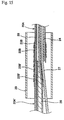
- Figure 17 is an enlarged cross section of the joint 30 between this first proximal shaft 31A and second proximal shaft 31A'.
- the distal end of the second proximal shaft 31A' gradually tapers off in diameter so as to join continuously (smoothly) with the outer peripheral surface of the first proximal shaft 31A.
- the second proximal shaft 31A' it is preferable for the second proximal shaft 31A' to be composed of a material with higher rigidity than that of the first proximal shaft 31A.
- a metal tube such as a hypodermic injection tube, or a metal tube whose outer surface is covered with a resin
- a tube composed of a resin with a high elastic modulus, such as a polyimide can be used as this second proximal shaft 31A'
- the second proximal shaft 31A' composed of this material is advantageous in terms of management, in that the tolerance in the inside diameter thereof can be kept extremely low, so the tolerance in the bonding clearance between the first proximal shaft 31A and the second proximal shaft 31A' will be small.
- a reinforcing wire 33 is provided on the inside along both shafts 31A and 31A'.
- the catheter shaft illustrated in Figures 16 and 17 was produced as Example 4.
- the distal shaft and first proximal shaft of this Example 4 are the same as in Example 3 above, and were formed entirely by extrusion molding using a polyamide elastomer (trade name "Pebax 7233SA00,” made by Elf Atochem) (outside diameter of proximal shaft: 0.88 mm, outside diameter of distal shaft: 0.91 mm).
- the overall length of the first proximal shaft was adjusted to approximately 7 cm, and the overall length of the distal shaft to approximately 25 cm.
- the tube provided to the inner surface of the guide wire lumen of this distal shaft was formed by extrusion molding using a high-density polyethylene (trade name "HY540, made by Mitsubishi Chemical), just as in Example 3 above.
- the second proximal shaft was formed from a material with higher rigidity than that of the distal shaft and first proximal shaft, and was fitted and joined to the first proximal shaft using a cyanoacrylate-based adhesive agent (trade name "4011" and "4014,” made by Loctite).
- a cyanoacrylate-based adhesive agent trade name "4011" and "4014,” made by Loctite.
- a urethane-based adhesive agent or other type besides a cyanoacrylate-based adhesive agent may be used here if the tube of the bonded portion is formed flexibly. although the length of the adhesive curing time may be sacrificed.
- the monorail type balloon catheter equipped with the catheter shaft of this Example 4 had good pushability, was easy to manipulate, etc.
- both the proximal shaft and the distal shaft had a dual-lumen structure, but the present invention is not limited to this, and the structure of the proximal shaft may be changed to a single-lumen structure.
- the structure of the catheter shaft pertaining to the present invention is related to a balloon catheter, but can, of course, also be applied to intravascular diagnostic catheters, including intravascular ultrasound diagnostic catheters, radiation catheters, intravascular drug injection catheters, and various atelectomy catheters.
- the balloon catheter pertaining to the present invention and the methods for manufacturing the catheter shaft and balloon thereof, are suited to use in the fields of in percutaneous transluminal angioplasty (PTA) or percutaneous transluminal coronary angioplasty (PTCA), in which constricted areas or obstructions such as in the coronary artery, limb arteries, the renal artery, or peripheral vessels are treated by dilation.
- PTA percutaneous transluminal angioplasty
- PTCA percutaneous transluminal coronary angioplasty
Applications Claiming Priority (3)
| Application Number | Priority Date | Filing Date | Title |
|---|---|---|---|
| JP1953998 | 1998-01-30 | ||
| JP1953998 | 1998-01-30 | ||
| PCT/JP1998/004504 WO1999038557A1 (fr) | 1998-01-30 | 1998-10-05 | Sonde a ballonnet, tige de sonde associee et procede de production de ballonnet |
Publications (3)
| Publication Number | Publication Date |
|---|---|
| EP1051990A1 true EP1051990A1 (fr) | 2000-11-15 |
| EP1051990A4 EP1051990A4 (fr) | 2006-04-19 |
| EP1051990B1 EP1051990B1 (fr) | 2008-10-29 |
Family
ID=12002132
Family Applications (1)
| Application Number | Title | Priority Date | Filing Date |
|---|---|---|---|
| EP98945628A Expired - Lifetime EP1051990B1 (fr) | 1998-01-30 | 1998-10-05 | Sonde ä ballonnet et procédé de production |
Country Status (9)
| Country | Link |
|---|---|
| EP (1) | EP1051990B1 (fr) |
| JP (1) | JP4345229B2 (fr) |
| KR (1) | KR100523521B1 (fr) |
| CN (1) | CN1224430C (fr) |
| AU (1) | AU9284198A (fr) |
| CA (1) | CA2310466A1 (fr) |
| DE (1) | DE69840178D1 (fr) |
| HK (1) | HK1035503A1 (fr) |
| WO (1) | WO1999038557A1 (fr) |
Cited By (18)
| Publication number | Priority date | Publication date | Assignee | Title |
|---|---|---|---|---|
| WO2001056645A1 (fr) * | 2000-02-04 | 2001-08-09 | Boston Scientific Limited | Catheters manipulables par un seul operateur et leurs procedes d'utilisation |
| EP1251899A1 (fr) * | 2000-02-04 | 2002-10-30 | C. R. Bard, Inc. | Catheter a ballonnet et a trois lumieres destine a l'elimination de calculs |
| WO2002076545A3 (fr) * | 2001-03-21 | 2003-11-27 | Datascope Investment Corp | Catheter a ballonnet intra-aortique comportant un element rapporte de lumiere de gaz |
| WO2003097154A1 (fr) * | 2002-05-15 | 2003-11-27 | Medilator | Dilatateur servant a elargir un passage vers un corps |
| WO2008115399A1 (fr) | 2007-03-15 | 2008-09-25 | Senorx, Inc. | Cathéter à corps mou ayant une lumière à faible frottement |
| US8057379B2 (en) | 2005-11-18 | 2011-11-15 | Senorx, Inc. | Treatment of a body cavity |
| US8075469B2 (en) | 2005-11-18 | 2011-12-13 | Senorx, Inc. | Methods for asymmetrical irradiation of a body cavity |
| US8277370B2 (en) | 2007-03-12 | 2012-10-02 | Senorx, Inc. | Radiation catheter with multilayered balloon |
| US8292794B2 (en) | 2002-11-06 | 2012-10-23 | Senorx, Inc. | Method for maintaining access to a biopsy site |
| US8398535B2 (en) | 2002-11-06 | 2013-03-19 | Senorx, Inc. | Catheter assembly for delivering a radiation source into a body cavity |
| US8740763B2 (en) | 2008-01-24 | 2014-06-03 | Hologic Inc. | Multilumen brachytherapy balloon catheter |
| EP2801385A1 (fr) | 2013-05-07 | 2014-11-12 | Imds R&D Bv | Cathéter à ballonnet |
| US9623260B2 (en) | 2004-11-05 | 2017-04-18 | Theragenics Corporation | Expandable brachytherapy device |
| US10022557B2 (en) | 2010-09-30 | 2018-07-17 | Hologic, Inc. | Using a guided member to facilitate brachytherapy device swap |
| US10207126B2 (en) | 2009-05-11 | 2019-02-19 | Cytyc Corporation | Lumen visualization and identification system for multi-lumen balloon catheter |
| US10342992B2 (en) | 2011-01-06 | 2019-07-09 | Hologic, Inc. | Orienting a brachytherapy applicator |
| US10449336B2 (en) | 2015-08-11 | 2019-10-22 | The Spectranetics Corporation | Temporary occlusions balloon devices and methods for preventing blood flow through a vascular perforation |
| EP3789074A1 (fr) * | 2019-08-28 | 2021-03-10 | Sino Medical Sciences Technology Inc. | Cathéter à ballonnet |
Families Citing this family (30)
| Publication number | Priority date | Publication date | Assignee | Title |
|---|---|---|---|---|
| US6606515B1 (en) | 1996-09-13 | 2003-08-12 | Scimed Life Systems, Inc. | Guide wire insertion and re-insertion tools and methods of use |
| US6582401B1 (en) | 1996-09-13 | 2003-06-24 | Scimed Life Sytems, Inc. | Multi-size convertible catheter |
| US6096009A (en) | 1996-09-13 | 2000-08-01 | Boston Scientific Corporation | Guidewire and catheter locking device and method |
| JP4922498B2 (ja) * | 2001-05-11 | 2012-04-25 | 株式会社カネカ | バルーン用パリソン |
| US8480629B2 (en) | 2005-01-28 | 2013-07-09 | Boston Scientific Scimed, Inc. | Universal utility board for use with medical devices and methods of use |
| JP4549933B2 (ja) * | 2005-06-08 | 2010-09-22 | ジョンソン・エンド・ジョンソン株式会社 | 血管カテーテル |
| EP1892007B1 (fr) * | 2005-06-14 | 2011-10-26 | Vayu Co., Ltd | Cathéter à ballonnet |
| US8273006B2 (en) | 2005-11-18 | 2012-09-25 | Senorx, Inc. | Tissue irradiation |
| JP4885593B2 (ja) * | 2006-03-31 | 2012-02-29 | 株式会社東海メディカルプロダクツ | バルーンカテーテル |
| US8372000B2 (en) | 2007-01-03 | 2013-02-12 | Boston Scientific Scimed, Inc. | Method and apparatus for biliary access and stone retrieval |
| US8388521B2 (en) | 2008-05-19 | 2013-03-05 | Boston Scientific Scimed, Inc. | Integrated locking device with active sealing |
| US8343041B2 (en) | 2008-05-19 | 2013-01-01 | Boston Scientific Scimed, Inc. | Integrated locking device with passive sealing |
| US9248311B2 (en) | 2009-02-11 | 2016-02-02 | Hologic, Inc. | System and method for modifying a flexibility of a brachythereapy catheter |
| US9579524B2 (en) | 2009-02-11 | 2017-02-28 | Hologic, Inc. | Flexible multi-lumen brachytherapy device |
| US9370643B2 (en) * | 2011-06-23 | 2016-06-21 | W.L. Gore & Associates, Inc. | High strength balloon cover |
| WO2013003450A1 (fr) | 2011-06-27 | 2013-01-03 | Boston Scientific Scimed, Inc. | Systèmes de pose de stent et procédés de fabrication et d'utilisation de systèmes de pose de stent |
| US9358042B2 (en) | 2013-03-13 | 2016-06-07 | The Spectranetics Corporation | Expandable member for perforation occlusion |
| CN104740748B (zh) * | 2013-12-31 | 2019-06-11 | 微创神通医疗科技(上海)有限公司 | 一种导引导管 |
| US10736691B2 (en) | 2014-06-26 | 2020-08-11 | Cook Medical Technologies Llc | Surface energy enhancement of lubricious objects |
| CN105311730A (zh) * | 2014-07-31 | 2016-02-10 | 微创神通医疗科技(上海)有限公司 | 导引导管 |
| JP5813842B2 (ja) * | 2014-09-22 | 2015-11-17 | 朝日インテック株式会社 | バルーンカテーテル |
| CN104434258A (zh) * | 2014-11-28 | 2015-03-25 | 苏州亘科医疗科技有限公司 | 一种多功能球囊扩张导管 |
| US10499892B2 (en) | 2015-08-11 | 2019-12-10 | The Spectranetics Corporation | Temporary occlusion balloon devices and methods for preventing blood flow through a vascular perforation |
| JP6921660B2 (ja) * | 2016-07-06 | 2021-08-18 | 株式会社カネカ | ガイドワイヤサポートカテーテル |
| US11064870B2 (en) | 2017-08-11 | 2021-07-20 | Boston Scientific Limited | Biopsy cap for use with endoscope |
| TWI785200B (zh) * | 2018-02-09 | 2022-12-01 | 日商東麗股份有限公司 | 氣球導管 |
| WO2020012851A1 (fr) * | 2018-07-09 | 2020-01-16 | 株式会社グッドマン | Cathéter à ballonnet |
| WO2023157535A1 (fr) * | 2022-02-18 | 2023-08-24 | 株式会社カネカ | Cathéter à ballon |
| WO2023157533A1 (fr) * | 2022-02-18 | 2023-08-24 | 株式会社カネカ | Cathéter à ballonnet |
| CN114796809A (zh) * | 2022-03-30 | 2022-07-29 | 深圳市顺美医疗股份有限公司 | 球囊导引导管 |
Citations (13)
| Publication number | Priority date | Publication date | Assignee | Title |
|---|---|---|---|---|
| GB2073219A (en) * | 1980-02-29 | 1981-10-14 | Thoratec Lab Corp | Polymer surfaces for blood- contacting surfaces of a biomedical device, and methods for forming |
| US4373009A (en) * | 1981-05-18 | 1983-02-08 | International Silicone Corporation | Method of forming a hydrophilic coating on a substrate |
| US4464176A (en) * | 1982-06-04 | 1984-08-07 | Mallinckrodt, Inc. | Blood vessel catheter for medicine delivery and method of manufacture |
| EP0669142A2 (fr) * | 1994-01-31 | 1995-08-30 | Cordis Corporation | Cathéter à tubulure coextrudée |
| WO1995023619A1 (fr) * | 1994-03-02 | 1995-09-08 | Scimed Life Systems, Inc. | Ballonnets de catheter en elastomere de copolymere bloc |
| US5470322A (en) * | 1994-04-15 | 1995-11-28 | Danforth Biomedical Inc. | Reinforced multilumen catheter for axially varying stiffness |
| WO1996000099A1 (fr) * | 1994-06-24 | 1996-01-04 | Advanced Cardiovascular Systems Inc. | Catheters dotes d'un corps proximal reutilisable |
| WO1996025970A1 (fr) * | 1995-02-24 | 1996-08-29 | C.R. Bard, Inc. | Catheter a ballonnet du type monorail renforce |
| EP0768097A2 (fr) * | 1995-10-11 | 1997-04-16 | Terumo Kabushiki Kaisha | Ballonet de cathéter et cathéter à ballonet |
| US5645533A (en) * | 1991-07-05 | 1997-07-08 | Scimed Life Systems, Inc. | Apparatus and method for performing an intravascular procedure and exchanging an intravascular device |
| WO1997029800A1 (fr) * | 1996-02-13 | 1997-08-21 | Cardiovascular Dynamics, Inc. | Tige de catheter hybride |
| JPH10290837A (ja) * | 1997-04-18 | 1998-11-04 | Kanegafuchi Chem Ind Co Ltd | バルーンカテーテル及びそれに用いるマルチルーメンシャフトの製造方法 |
| JPH10314297A (ja) * | 1997-05-15 | 1998-12-02 | Kanegafuchi Chem Ind Co Ltd | バルーンカテーテル及びそれに用いるバルーンの製造方法 |
Family Cites Families (11)
| Publication number | Priority date | Publication date | Assignee | Title |
|---|---|---|---|---|
| DE3442736A1 (de) | 1984-11-23 | 1986-06-05 | Tassilo Dr.med. 7800 Freiburg Bonzel | Dilatationskatheter |
| US4782834A (en) | 1987-01-06 | 1988-11-08 | Advanced Cardiovascular Systems, Inc. | Dual lumen dilatation catheter and method of manufacturing the same |
| US4748982A (en) | 1987-01-06 | 1988-06-07 | Advanced Cardiovascular Systems, Inc. | Reinforced balloon dilatation catheter with slitted exchange sleeve and method |
| US4844986A (en) * | 1988-02-16 | 1989-07-04 | Becton, Dickinson And Company | Method for preparing lubricated surfaces and product |
| EP0638327B1 (fr) | 1989-01-30 | 2008-08-20 | C.R. Bard, Inc. | Cathéter coronaire rapidement échangeable |
| US5289831A (en) * | 1989-03-09 | 1994-03-01 | Vance Products Incorporated | Surface-treated stent, catheter, cannula, and the like |
| AU648387B2 (en) * | 1991-03-04 | 1994-04-21 | Medex, Inc. | Use of surfactants to improve intravenous catheter flashback |
| AU664187B2 (en) | 1991-09-16 | 1995-11-09 | Cook Incorporated | Soft tip angioplasty balloon catheter |
| EP0580845B1 (fr) | 1992-02-10 | 1998-11-11 | Scimed Life Systems, Inc. | Catheter intravasculaire comportant un passage de fil de guidage distal |
| US5382234A (en) | 1993-04-08 | 1995-01-17 | Scimed Life Systems, Inc. | Over-the-wire balloon catheter |
| PL307507A1 (en) * | 1993-06-21 | 1995-05-29 | Baxter Int | Self-venting fluid transmission system |
-
1998
- 1998-10-05 DE DE69840178T patent/DE69840178D1/de not_active Expired - Lifetime
- 1998-10-05 KR KR10-2000-7003791A patent/KR100523521B1/ko active IP Right Grant
- 1998-10-05 WO PCT/JP1998/004504 patent/WO1999038557A1/fr active IP Right Grant
- 1998-10-05 AU AU92841/98A patent/AU9284198A/en not_active Abandoned
- 1998-10-05 EP EP98945628A patent/EP1051990B1/fr not_active Expired - Lifetime
- 1998-10-05 CN CNB988128160A patent/CN1224430C/zh not_active Expired - Lifetime
- 1998-10-05 JP JP2000529287A patent/JP4345229B2/ja not_active Expired - Fee Related
- 1998-10-05 CA CA002310466A patent/CA2310466A1/fr not_active Abandoned
-
2001
- 2001-08-27 HK HK01106018A patent/HK1035503A1/xx not_active IP Right Cessation
Patent Citations (13)
| Publication number | Priority date | Publication date | Assignee | Title |
|---|---|---|---|---|
| GB2073219A (en) * | 1980-02-29 | 1981-10-14 | Thoratec Lab Corp | Polymer surfaces for blood- contacting surfaces of a biomedical device, and methods for forming |
| US4373009A (en) * | 1981-05-18 | 1983-02-08 | International Silicone Corporation | Method of forming a hydrophilic coating on a substrate |
| US4464176A (en) * | 1982-06-04 | 1984-08-07 | Mallinckrodt, Inc. | Blood vessel catheter for medicine delivery and method of manufacture |
| US5645533A (en) * | 1991-07-05 | 1997-07-08 | Scimed Life Systems, Inc. | Apparatus and method for performing an intravascular procedure and exchanging an intravascular device |
| EP0669142A2 (fr) * | 1994-01-31 | 1995-08-30 | Cordis Corporation | Cathéter à tubulure coextrudée |
| WO1995023619A1 (fr) * | 1994-03-02 | 1995-09-08 | Scimed Life Systems, Inc. | Ballonnets de catheter en elastomere de copolymere bloc |
| US5470322A (en) * | 1994-04-15 | 1995-11-28 | Danforth Biomedical Inc. | Reinforced multilumen catheter for axially varying stiffness |
| WO1996000099A1 (fr) * | 1994-06-24 | 1996-01-04 | Advanced Cardiovascular Systems Inc. | Catheters dotes d'un corps proximal reutilisable |
| WO1996025970A1 (fr) * | 1995-02-24 | 1996-08-29 | C.R. Bard, Inc. | Catheter a ballonnet du type monorail renforce |
| EP0768097A2 (fr) * | 1995-10-11 | 1997-04-16 | Terumo Kabushiki Kaisha | Ballonet de cathéter et cathéter à ballonet |
| WO1997029800A1 (fr) * | 1996-02-13 | 1997-08-21 | Cardiovascular Dynamics, Inc. | Tige de catheter hybride |
| JPH10290837A (ja) * | 1997-04-18 | 1998-11-04 | Kanegafuchi Chem Ind Co Ltd | バルーンカテーテル及びそれに用いるマルチルーメンシャフトの製造方法 |
| JPH10314297A (ja) * | 1997-05-15 | 1998-12-02 | Kanegafuchi Chem Ind Co Ltd | バルーンカテーテル及びそれに用いるバルーンの製造方法 |
Non-Patent Citations (3)
| Title |
|---|
| PATENT ABSTRACTS OF JAPAN vol. 1999, no. 02, 26 February 1999 (1999-02-26) & JP 10 290837 A (KANEGAFUCHI CHEM IND CO LTD), 4 November 1998 (1998-11-04) * |
| PATENT ABSTRACTS OF JAPAN vol. 1999, no. 03, 31 March 1999 (1999-03-31) & JP 10 314297 A (KANEGAFUCHI CHEM IND CO LTD), 2 December 1998 (1998-12-02) * |
| See also references of WO9938557A1 * |
Cited By (32)
| Publication number | Priority date | Publication date | Assignee | Title |
|---|---|---|---|---|
| EP1251899A1 (fr) * | 2000-02-04 | 2002-10-30 | C. R. Bard, Inc. | Catheter a ballonnet et a trois lumieres destine a l'elimination de calculs |
| EP1251899A4 (fr) * | 2000-02-04 | 2007-07-18 | Conmed Endoscopic Technologies | Catheter a ballonnet et a trois lumieres destine a l'elimination de calculs |
| WO2001056645A1 (fr) * | 2000-02-04 | 2001-08-09 | Boston Scientific Limited | Catheters manipulables par un seul operateur et leurs procedes d'utilisation |
| US7481800B2 (en) | 2000-02-04 | 2009-01-27 | Conmed Endoscopic Technologies | Triple lumen stone balloon catheter and method |
| WO2002076545A3 (fr) * | 2001-03-21 | 2003-11-27 | Datascope Investment Corp | Catheter a ballonnet intra-aortique comportant un element rapporte de lumiere de gaz |
| WO2003097154A1 (fr) * | 2002-05-15 | 2003-11-27 | Medilator | Dilatateur servant a elargir un passage vers un corps |
| US8292794B2 (en) | 2002-11-06 | 2012-10-23 | Senorx, Inc. | Method for maintaining access to a biopsy site |
| US8517906B2 (en) | 2002-11-06 | 2013-08-27 | Hologic, Inc. | Brachytherapy device |
| US8398535B2 (en) | 2002-11-06 | 2013-03-19 | Senorx, Inc. | Catheter assembly for delivering a radiation source into a body cavity |
| US8328710B2 (en) | 2002-11-06 | 2012-12-11 | Senorx, Inc. | Temporary catheter for biopsy site tissue fixation |
| US9623260B2 (en) | 2004-11-05 | 2017-04-18 | Theragenics Corporation | Expandable brachytherapy device |
| US9808650B2 (en) | 2004-11-05 | 2017-11-07 | Theragenics Corporation | Expandable brachytherapy device |
| US9415239B2 (en) | 2005-11-18 | 2016-08-16 | Hologic, Inc. | Brachytherapy device for facilitating asymmetrical irradiation of a body cavity |
| US9180312B2 (en) | 2005-11-18 | 2015-11-10 | Hologic, Inc. | Brachytherapy device for asymmetrical irradiation of a body cavity |
| US8079946B2 (en) | 2005-11-18 | 2011-12-20 | Senorx, Inc. | Asymmetrical irradiation of a body cavity |
| US8075469B2 (en) | 2005-11-18 | 2011-12-13 | Senorx, Inc. | Methods for asymmetrical irradiation of a body cavity |
| US8057379B2 (en) | 2005-11-18 | 2011-11-15 | Senorx, Inc. | Treatment of a body cavity |
| US8636637B2 (en) | 2005-11-18 | 2014-01-28 | Hologic, Inc | Methods for asymmetrical irradiation of a body cavity |
| US8251884B2 (en) | 2005-11-18 | 2012-08-28 | Senorx, Inc. | Methods for asymmetrical irradiation of a body cavity |
| US10413750B2 (en) | 2005-11-18 | 2019-09-17 | Hologic, Inc. | Brachytherapy device for facilitating asymmetrical irradiation of a body cavity |
| US8758214B2 (en) | 2007-03-12 | 2014-06-24 | Hologic, Inc. | Radiation catheter with multilayered balloon |
| US8287442B2 (en) | 2007-03-12 | 2012-10-16 | Senorx, Inc. | Radiation catheter with multilayered balloon |
| US8277370B2 (en) | 2007-03-12 | 2012-10-02 | Senorx, Inc. | Radiation catheter with multilayered balloon |
| US8740873B2 (en) | 2007-03-15 | 2014-06-03 | Hologic, Inc. | Soft body catheter with low friction lumen |
| WO2008115399A1 (fr) | 2007-03-15 | 2008-09-25 | Senorx, Inc. | Cathéter à corps mou ayant une lumière à faible frottement |
| US8740763B2 (en) | 2008-01-24 | 2014-06-03 | Hologic Inc. | Multilumen brachytherapy balloon catheter |
| US10207126B2 (en) | 2009-05-11 | 2019-02-19 | Cytyc Corporation | Lumen visualization and identification system for multi-lumen balloon catheter |
| US10022557B2 (en) | 2010-09-30 | 2018-07-17 | Hologic, Inc. | Using a guided member to facilitate brachytherapy device swap |
| US10342992B2 (en) | 2011-01-06 | 2019-07-09 | Hologic, Inc. | Orienting a brachytherapy applicator |
| EP2801385A1 (fr) | 2013-05-07 | 2014-11-12 | Imds R&D Bv | Cathéter à ballonnet |
| US10449336B2 (en) | 2015-08-11 | 2019-10-22 | The Spectranetics Corporation | Temporary occlusions balloon devices and methods for preventing blood flow through a vascular perforation |
| EP3789074A1 (fr) * | 2019-08-28 | 2021-03-10 | Sino Medical Sciences Technology Inc. | Cathéter à ballonnet |
Also Published As
| Publication number | Publication date |
|---|---|
| KR20010031005A (ko) | 2001-04-16 |
| CN1285763A (zh) | 2001-02-28 |
| EP1051990A4 (fr) | 2006-04-19 |
| EP1051990B1 (fr) | 2008-10-29 |
| DE69840178D1 (de) | 2008-12-11 |
| WO1999038557A1 (fr) | 1999-08-05 |
| HK1035503A1 (en) | 2001-11-30 |
| CN1224430C (zh) | 2005-10-26 |
| CA2310466A1 (fr) | 1999-08-05 |
| AU9284198A (en) | 1999-08-16 |
| JP4345229B2 (ja) | 2009-10-14 |
| KR100523521B1 (ko) | 2005-10-24 |
Similar Documents
| Publication | Publication Date | Title |
|---|---|---|
| EP1051990B1 (fr) | Sonde ä ballonnet et procédé de production | |
| US8088121B2 (en) | Catheter | |
| EP1023913B1 (fr) | Catheter a ballonnet et procede de fabrication | |
| US6620128B1 (en) | Balloon blowing process with metered volumetric inflation | |
| KR101112717B1 (ko) | 풍선 카테테르 | |
| EP0540858B2 (fr) | Objet gonflable ayant une expansion élastique limitée | |
| US9095689B2 (en) | Non-compliant multilayered balloon for a catheter | |
| JP3602147B2 (ja) | 拡張カテーテル用の多層高強度バルーン | |
| EP2043722B1 (fr) | Cathéter à ballonnet présentant une grande résistance et une grande flexibilité | |
| CA2208548A1 (fr) | Catheter a ballon a longueur variable | |
| WO1996019256A9 (fr) | Catheter a ballon a longueur variable | |
| US20090254113A1 (en) | Dilatation balloon with ridges and methods | |
| US6589226B1 (en) | Catheter shaft and method of making a catheter shaft | |
| US6641694B1 (en) | Angioplasty balloon with thin-walled taper and method of making the same | |
| JP5107788B2 (ja) | バルーンカテーテルおよびバルーンカテーテル用コネクタ | |
| JP2008110132A (ja) | カテーテル | |
| WO2003039628A2 (fr) | Catheter a ballonnet non glissant | |
| EP1625869A1 (fr) | Catheter a ballonnet et son procede de fabrication | |
| JP4815657B2 (ja) | 医療用ポリマーブレンド材料およびこの材料を用いた医療用バルーン | |
| US6712833B1 (en) | Method of making a catheter balloon | |
| US20020171180A1 (en) | Method of making a catheter balloon | |
| JPH11244385A (ja) | 医療用バルーンカテーテルシャフト及びその製造方法 | |
| JP2001314512A (ja) | 均一膜厚バルーンおよびバルーンカテーテル |
Legal Events
| Date | Code | Title | Description |
|---|---|---|---|
| PUAI | Public reference made under article 153(3) epc to a published international application that has entered the european phase |
Free format text: ORIGINAL CODE: 0009012 |
|
| 17P | Request for examination filed |
Effective date: 20000616 |
|
| AK | Designated contracting states |
Kind code of ref document: A1 Designated state(s): DE FR GB IT |
|
| RIC1 | Information provided on ipc code assigned before grant |
Ipc: A61L 33/00 19850101ALI20051115BHEP Ipc: A61M 25/10 19900101AFI19990817BHEP |
|
| A4 | Supplementary search report drawn up and despatched |
Effective date: 20060302 |
|
| 17Q | First examination report despatched |
Effective date: 20060824 |
|
| GRAP | Despatch of communication of intention to grant a patent |
Free format text: ORIGINAL CODE: EPIDOSNIGR1 |
|
| RTI1 | Title (correction) |
Free format text: BALLOON CATHETER AND METHOD OF PRODUCTION |
|
| GRAS | Grant fee paid |
Free format text: ORIGINAL CODE: EPIDOSNIGR3 |
|
| GRAA | (expected) grant |
Free format text: ORIGINAL CODE: 0009210 |
|
| AK | Designated contracting states |
Kind code of ref document: B1 Designated state(s): DE FR GB IT |
|
| REG | Reference to a national code |
Ref country code: GB Ref legal event code: FG4D |
|
| REF | Corresponds to: |
Ref document number: 69840178 Country of ref document: DE Date of ref document: 20081211 Kind code of ref document: P |
|
| PLBE | No opposition filed within time limit |
Free format text: ORIGINAL CODE: 0009261 |
|
| STAA | Information on the status of an ep patent application or granted ep patent |
Free format text: STATUS: NO OPPOSITION FILED WITHIN TIME LIMIT |
|
| 26N | No opposition filed |
Effective date: 20090730 |
|
| PG25 | Lapsed in a contracting state [announced via postgrant information from national office to epo] |
Ref country code: GB Free format text: LAPSE BECAUSE OF NON-PAYMENT OF DUE FEES Effective date: 20091005 |
|
| REG | Reference to a national code |
Ref country code: FR Ref legal event code: CA Effective date: 20130416 |
|
| REG | Reference to a national code |
Ref country code: FR Ref legal event code: PLFP Year of fee payment: 18 |
|
| REG | Reference to a national code |
Ref country code: FR Ref legal event code: PLFP Year of fee payment: 19 |
|
| REG | Reference to a national code |
Ref country code: FR Ref legal event code: PLFP Year of fee payment: 20 |
|
| PGFP | Annual fee paid to national office [announced via postgrant information from national office to epo] |
Ref country code: FR Payment date: 20170918 Year of fee payment: 20 |
|
| PGFP | Annual fee paid to national office [announced via postgrant information from national office to epo] |
Ref country code: DE Payment date: 20170927 Year of fee payment: 20 |
|
| PGFP | Annual fee paid to national office [announced via postgrant information from national office to epo] |
Ref country code: IT Payment date: 20171024 Year of fee payment: 20 |
|
| REG | Reference to a national code |
Ref country code: DE Ref legal event code: R071 Ref document number: 69840178 Country of ref document: DE |