EP1051273B1 - Verfahren zum herstellen eines zylinderkopfes einer brennkraftmaschine - Google Patents
Verfahren zum herstellen eines zylinderkopfes einer brennkraftmaschine Download PDFInfo
- Publication number
- EP1051273B1 EP1051273B1 EP98964397A EP98964397A EP1051273B1 EP 1051273 B1 EP1051273 B1 EP 1051273B1 EP 98964397 A EP98964397 A EP 98964397A EP 98964397 A EP98964397 A EP 98964397A EP 1051273 B1 EP1051273 B1 EP 1051273B1
- Authority
- EP
- European Patent Office
- Prior art keywords
- sheet
- cylinder head
- metal separating
- combustion engine
- internal combustion
- Prior art date
- Legal status (The legal status is an assumption and is not a legal conclusion. Google has not performed a legal analysis and makes no representation as to the accuracy of the status listed.)
- Expired - Lifetime
Links
Images

Classifications
-
- B—PERFORMING OPERATIONS; TRANSPORTING
- B22—CASTING; POWDER METALLURGY
- B22D—CASTING OF METALS; CASTING OF OTHER SUBSTANCES BY THE SAME PROCESSES OR DEVICES
- B22D19/00—Casting in, on, or around objects which form part of the product
-
- F—MECHANICAL ENGINEERING; LIGHTING; HEATING; WEAPONS; BLASTING
- F02—COMBUSTION ENGINES; HOT-GAS OR COMBUSTION-PRODUCT ENGINE PLANTS
- F02F—CYLINDERS, PISTONS OR CASINGS, FOR COMBUSTION ENGINES; ARRANGEMENTS OF SEALINGS IN COMBUSTION ENGINES
- F02F1/00—Cylinders; Cylinder heads
- F02F1/24—Cylinder heads
- F02F1/42—Shape or arrangement of intake or exhaust channels in cylinder heads
- F02F1/4235—Shape or arrangement of intake or exhaust channels in cylinder heads of intake channels
- F02F1/4242—Shape or arrangement of intake or exhaust channels in cylinder heads of intake channels with a partition wall inside the channel
-
- B—PERFORMING OPERATIONS; TRANSPORTING
- B22—CASTING; POWDER METALLURGY
- B22D—CASTING OF METALS; CASTING OF OTHER SUBSTANCES BY THE SAME PROCESSES OR DEVICES
- B22D19/00—Casting in, on, or around objects which form part of the product
- B22D19/0009—Cylinders, pistons
-
- F—MECHANICAL ENGINEERING; LIGHTING; HEATING; WEAPONS; BLASTING
- F02—COMBUSTION ENGINES; HOT-GAS OR COMBUSTION-PRODUCT ENGINE PLANTS
- F02F—CYLINDERS, PISTONS OR CASINGS, FOR COMBUSTION ENGINES; ARRANGEMENTS OF SEALINGS IN COMBUSTION ENGINES
- F02F1/00—Cylinders; Cylinder heads
- F02F1/24—Cylinder heads
- F02F1/42—Shape or arrangement of intake or exhaust channels in cylinder heads
-
- F—MECHANICAL ENGINEERING; LIGHTING; HEATING; WEAPONS; BLASTING
- F02—COMBUSTION ENGINES; HOT-GAS OR COMBUSTION-PRODUCT ENGINE PLANTS
- F02F—CYLINDERS, PISTONS OR CASINGS, FOR COMBUSTION ENGINES; ARRANGEMENTS OF SEALINGS IN COMBUSTION ENGINES
- F02F1/00—Cylinders; Cylinder heads
- F02F1/24—Cylinder heads
- F02F2001/244—Arrangement of valve stems in cylinder heads
- F02F2001/245—Arrangement of valve stems in cylinder heads the valve stems being orientated at an angle with the cylinder axis
-
- F—MECHANICAL ENGINEERING; LIGHTING; HEATING; WEAPONS; BLASTING
- F02—COMBUSTION ENGINES; HOT-GAS OR COMBUSTION-PRODUCT ENGINE PLANTS
- F02F—CYLINDERS, PISTONS OR CASINGS, FOR COMBUSTION ENGINES; ARRANGEMENTS OF SEALINGS IN COMBUSTION ENGINES
- F02F2200/00—Manufacturing
- F02F2200/06—Casting
-
- Y—GENERAL TAGGING OF NEW TECHNOLOGICAL DEVELOPMENTS; GENERAL TAGGING OF CROSS-SECTIONAL TECHNOLOGIES SPANNING OVER SEVERAL SECTIONS OF THE IPC; TECHNICAL SUBJECTS COVERED BY FORMER USPC CROSS-REFERENCE ART COLLECTIONS [XRACs] AND DIGESTS
- Y02—TECHNOLOGIES OR APPLICATIONS FOR MITIGATION OR ADAPTATION AGAINST CLIMATE CHANGE
- Y02T—CLIMATE CHANGE MITIGATION TECHNOLOGIES RELATED TO TRANSPORTATION
- Y02T10/00—Road transport of goods or passengers
- Y02T10/10—Internal combustion engine [ICE] based vehicles
- Y02T10/12—Improving ICE efficiencies
Definitions
- the invention relates to a method for producing a cylinder head of an internal combustion engine with sand cores to form an inlet duct for the combustion air supply into the Internal combustion engine, in particular for a motor vehicle, in at least one Gas flow channel is arranged a partition plate, which in the sand core of the corresponding is arranged with a partition plate to be provided gas flow channel, according to the The preamble of claim 1.
- the invention further relates to a partition plate according to the preamble of claim 4.
- the present invention has for its object to provide a method of the type mentioned above To provide, the above disadvantages are overcome and a Cylinder head is achieved with a very thin divider in gas flow channels.
- the partition plate as Tumble plate with side flags and with a longitudinal slot, which the tumble plate on divides downstream end into two legs, formed and arranged in the sand core in this way is that the side flags protrude from the sand core and the tumble plate is arranged spaced from ends of the inlet channel.
- the partition plate is formed with side mounting eyes, which are made of protrude from the sand core.
- Chill casting is preferably used as the casting process, here the individual ones Sand cores are used in a steel box, with the cores after the casting process dissolve. The tumble plate then remains, which thus enters the inlet channel is integrated.
- the mold casting is expediently a gray cast iron or an aluminum cast iron, alternatively also a Magnesium casting.
- a partition plate is designed as a tumble plate and has lateral ones Mounting ears and a two-leg longitudinal slot.
- this shows in advantageously a material thickness of 0.6 to 1.5 mm, preferably of 0.6 to 1.0 mm, especially 0.8 mm or less.
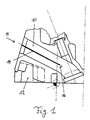
- Fig. 1 shows an intake port 10 in a cylinder head 12 otherwise not closer illustrated internal combustion engine.
- a partition in the form of a Tumble plates 14 arranged in the form of a Tumble plates 14 arranged.
- the tumble plate 14 divides a gas flow into the inlet duct 10 two partial streams, which are arranged again at a downstream end 16 of the tumble plate unite.
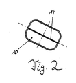
- Fig. 2 shows a view in the direction A of Fig. 1, the division of the inlet channel 10 by the Tumble plate 14.
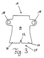
- FIG. 3 illustrates a preferred embodiment of a partition plate according to the invention 14. This is made before the casting of the cylinder head 12 and has two initially serving as assembly ears flags 18. At a downstream end 20 of the partition plate 14, a longitudinal slot 22 is formed, which the partition plate 14 thereon End divided into two legs 24. According to the invention, this partition 14 is in one Baked sand core 26 for a mold casting of the cylinder head 12, this being lost Sandkem 26 forms the inlet channel 10 during the casting process.
- Such a sand core 26 with a baked separating plate 14 is shown in FIG. 4.
- the Flags 18 protrude from the sand core 26, so that this in one during the casting process formed wall of the inlet channel 10 protrude and for a firm anchoring of the partition 14 care in the inlet duct 10.
- the arrangement of sand core 26 and Partition plate 14 made such that part of a side region 28 of the partition plate 14 protrudes laterally from the sand core 26. This ensures that independent of manufacturing tolerances of the inlet channel 10 in each case in two in the area of the partition plate channels separated from one another in a gastight manner.
- the sand core 26 forms an outlet point for two gas channels.
- the separating plate 14 is arranged up to this junction point, wherein each leg 24 (Fig. 3) protrudes into an opening channel.
- each gas exchange channel can be used in the cylinder head 12, for example also on an exhaust gas duct, which exhaust gas leads out of the cylinder head or an exhaust gas recirculation duct, which exhaust gas returns to an intake air flow.
- the separating plate 14 can also be curved so as to be flexible.
- devices for receiving a shut-off device for one of the subchannels of the inlet channel 10 can already be provided on the separating plate 14 during its manufacture or before the casting.
Description
- Fig. 1
- einen Einlaßkanal eines Zylinderkopfes einer Brennkraftmaschine im Querschnitt,
- Fig. 2
- in einer Ansicht in Richtung Pfeil A von Fig. 1,
- Fig. 3
- eine bevorzugte Ausführungsform eines erfindungsgemäßen Trennbleches in Aufsicht und
- Fig. 4
- einen mit der bevorzugten Ausführungsform eines erfindungsgemäßen Trennbleches von Fig. 3 versehenen Sandkern für einen Kokillenguß in Aufsicht.
Ebenso können an dem Trennblech 14 bereits bei dessen Herstellung bzw. vor dem Eingießen Einrichtungen zur Aufnahme einer Absperreinrichtung für einen der Teilkanäle des Einlaßkanales 10 vorgesehen sein.
Claims (5)
- Verfahren zum Herstellen eines Zylinderkopfes einer Brennkraftmaschine mit Sandkernen zum Ausbilden eines Einlaßkanals zur Verbrennungsluftzuführung in die Brennkraftmaschine, insbesondere für ein Kraftfahrzeug, wobei in wenigstens einem Gasströmungskanal ein Trennblech angeordnet ist, welches in dem Sandkern des entsprechenden mit einem Trennblech zu versehenden Gasströmungskanals angeordnet ist,
dadurch gekennzeichnet, daß
vor dem Gießverfahren das Trennblech als Tumble-Blech mit seitlichen Fahnen und mit einem Längsschlitz, welcher das Tumble-Blech am stromabseitigen Ende in zwei Schenkel teilt, ausgebildet und in dem Sandkern derart angeordnet wird, daß die seitlichen Fahnen aus dem Sandkern herausragen und das Tumble-Blech beabstandet von Enden des Einlaßkanals angeordnet ist. - Verfahren nach Anspruch 1,
dadurch gekennzeichnet, daß
als Gießverfahren ein Kokillenguß angewendet wird. - Verfahren nach Anspruch 2,
dadurch gekennzeichnet, daß
der Kokillenguß ein Grauguß, Magnesiumguß oder ein Aluminiumguß ist. - Trennblech (14) für einen Gasströmungskanal (10) eines Zylinderkopfes (12) einer Brennkraftmaschine, insbesondere für ein Kraftfahrzeug,
dadurch gekennzeichnet, daß
das Trennblech (14) als Tumble-Blech ausgebildet ist und seitliche Montageohren (18) sowie einen zwei Schenkel (24) ausbildenden Längsschlitz (22) aufweist. - Trennblech (14) nach Anspruch 6 oder 7,
dadurch gekennzeichnet, daß
das Trennblech (14) eine Materialstärke von 0,5 bis 1,5 mm, vorzugsweise von 0,6 bis 1, mm, insbesondere 0,8 mm aufweist.
Applications Claiming Priority (3)
| Application Number | Priority Date | Filing Date | Title |
|---|---|---|---|
| DE19803867 | 1998-01-31 | ||
| DE19803867A DE19803867A1 (de) | 1998-01-31 | 1998-01-31 | Verfahren zum Herstellen eines Zylinderkopfes einer Brennkraftmaschine |
| PCT/EP1998/007254 WO1999038629A1 (de) | 1998-01-31 | 1998-11-12 | Verfahren zum herstellen eines zylinderkopfes einer brennkraftmaschine |
Publications (2)
| Publication Number | Publication Date |
|---|---|
| EP1051273A1 EP1051273A1 (de) | 2000-11-15 |
| EP1051273B1 true EP1051273B1 (de) | 2001-10-04 |
Family
ID=7856300
Family Applications (1)
| Application Number | Title | Priority Date | Filing Date |
|---|---|---|---|
| EP98964397A Expired - Lifetime EP1051273B1 (de) | 1998-01-31 | 1998-11-12 | Verfahren zum herstellen eines zylinderkopfes einer brennkraftmaschine |
Country Status (7)
| Country | Link |
|---|---|
| EP (1) | EP1051273B1 (de) |
| JP (1) | JP2002501829A (de) |
| KR (1) | KR20010034463A (de) |
| AT (1) | ATE206337T1 (de) |
| DE (2) | DE19803867A1 (de) |
| ES (1) | ES2165713T3 (de) |
| WO (1) | WO1999038629A1 (de) |
Families Citing this family (20)
| Publication number | Priority date | Publication date | Assignee | Title |
|---|---|---|---|---|
| DE19960626A1 (de) | 1999-12-16 | 2001-06-21 | Fev Motorentech Gmbh | Kolbenbrennkraftmaschine mit unterteiltem Gaseinlaßkanal |
| DE10036128A1 (de) * | 2000-07-25 | 2002-02-07 | Volkswagen Ag | Brennkraftmaschine und Verfahren zur aktiven Durchlüftung des Zylinderkurbelgehäuses derselben |
| DE10108729B4 (de) * | 2001-02-23 | 2006-04-13 | Audi Ag | Zylinderkopf einer Brennkraftmaschine mit einem Strömungskanal |
| DE10145876A1 (de) * | 2001-09-18 | 2003-04-10 | Daimler Chrysler Ag | Vorrichtung zur Herstellung eines Druckgussbauteils mit einem Kern und einem Einlegeteil |
| DE10260041A1 (de) * | 2002-12-19 | 2004-07-15 | Volkswagen Ag | Trennblech für einen Gaswechselkanal einer Brennkraftmaschine und Verfahren zur Herstellung |
| US6886516B2 (en) * | 2002-12-20 | 2005-05-03 | Nissan Motor Co., Ltd. | Cylinder head of internal combustion engine and method of producing same |
| EP1450056B1 (de) | 2003-02-19 | 2017-06-07 | Nissan Motor Co., Ltd. | Hochfeste Pleuelstange und Verfahren zu ihrer Herstellung |
| JP4330422B2 (ja) | 2003-10-20 | 2009-09-16 | 日産自動車株式会社 | 鋳包み対象板部材、吸気ポート用の仕切り板、吸気ポート成形用砂中子およびシリンダヘッド |
| JP4172371B2 (ja) | 2003-10-20 | 2008-10-29 | 日産自動車株式会社 | シリンダヘッドの製造方法 |
| EP1548263B1 (de) | 2003-10-20 | 2019-12-11 | Nissan Motor Co., Ltd. | Trennblech für einlasskanal und sandkern zur formung des einlasskanals und zylinderkopf |
| JP4330423B2 (ja) * | 2003-10-20 | 2009-09-16 | 日産自動車株式会社 | 鋳造装置 |
| JP2005120995A (ja) * | 2003-10-20 | 2005-05-12 | Nissan Motor Co Ltd | 吸気ポート用の仕切り板、吸気ポート成形用砂中子およびシリンダヘッド |
| DE102004002923B4 (de) * | 2004-01-20 | 2016-10-20 | Volkswagen Ag | Brennkraftmaschine mit Trennblech im Ansaugtrakt |
| DE102004005324A1 (de) * | 2004-02-04 | 2005-08-25 | Daimlerchrysler Ag | Sandkern und Verfahren zur Herstellung desselben |
| JP4400503B2 (ja) * | 2005-04-19 | 2010-01-20 | 日産自動車株式会社 | 吸気ポート用の仕切り板、吸気ポート成形用砂中子およびシリンダヘッド |
| DE102006031532B3 (de) * | 2006-07-07 | 2008-04-17 | Emil Müller GmbH | Wasserlöslicher Salzkern mit Funktionsbauteil |
| FR2921117A3 (fr) * | 2007-09-17 | 2009-03-20 | Renault Sas | Element de renfort de la structure mecanique d'une culasse de moteur thermique et culasse de moteur thermique comprenant un tel element de renfort |
| FR2923011B1 (fr) * | 2007-10-29 | 2010-02-26 | Renault Sas | Dispositif de test de conduit d'admission pour vehicule automobile |
| EP3428433B1 (de) * | 2016-03-09 | 2020-02-19 | Honda Motor Co., Ltd. | Verbrennungsmotoransaugstruktur |
| WO2019009348A1 (ja) * | 2017-07-05 | 2019-01-10 | 本田技研工業株式会社 | 内燃機関の吸気構造 |
Family Cites Families (17)
| Publication number | Priority date | Publication date | Assignee | Title |
|---|---|---|---|---|
| DD81934A (de) * | ||||
| AT278264B (de) * | 1968-03-13 | 1970-01-26 | Dueker Eisenwerk | Gießform zur Herstellung von Muffen oder Sicken aufweisenden Formstücken |
| DE2035939B1 (de) * | 1970-07-20 | 1972-02-03 | Kloeckner Humboldt Deutz Ag | Zylinderkopf für Brennkraftmaschinen |
| DE2745245A1 (de) * | 1976-10-09 | 1978-04-20 | Toyo Kogyo Co | Verbrennungsmotor |
| FR2367195A1 (fr) * | 1976-10-09 | 1978-05-05 | Toyo Kogyo Co | Dispositif d'admission perfectionne pour moteurs a combustion interne |
| JPS59122725A (ja) * | 1982-12-29 | 1984-07-16 | Mazda Motor Corp | エンジンの吸気装置 |
| YU43348B (en) * | 1984-03-13 | 1989-06-30 | Tam | Combined kernel for casting cylinders of grey cast iron for air cooled internal combustion motors |
| JPS61268849A (ja) * | 1985-05-24 | 1986-11-28 | Toyota Motor Corp | 内燃機関のシリンダヘツドの冷却水通路構造 |
| JPS6250064A (ja) * | 1985-08-29 | 1987-03-04 | Mitsubishi Motors Corp | 可変スワ−ルポ−トの製造方法 |
| DE3721021A1 (de) * | 1986-06-27 | 1988-01-21 | Aisin Seiki | Verfahren zur herstellung eines brennkraftmaschinenkolbens |
| JPH03283Y2 (de) * | 1986-07-24 | 1991-01-08 | ||
| DE3707256C1 (en) * | 1987-03-06 | 1988-07-07 | Halbergerhuette Gmbh | Core for the casting of grey cast iron cylinder blocks |
| DE4128544C2 (de) * | 1990-09-06 | 1999-08-12 | Volkswagen Ag | Verfahren zum Herstellen eines Zylinderkopfes mit einem Portliner |
| DE4130715C1 (en) * | 1991-09-14 | 1992-08-27 | Mtu Friedrichshafen Gmbh | Cast housing for IC engine exhaust lining - which is held loosely by support rings with axial and radial play between ends |
| DE19517079A1 (de) * | 1995-05-10 | 1996-11-14 | Bayerische Motoren Werke Ag | Luftansaugvorrichtung für Brennkraftmaschinen |
| DE19547490C1 (de) * | 1995-12-19 | 1997-01-23 | Daimler Benz Ag | Im Druckgußverfahren hergestellter Zylinderkopf einer flüssigkeitsgekühlten Brennkraftmaschine |
| DE19735012C1 (de) * | 1997-08-13 | 1998-09-03 | Daimler Benz Ag | Verfahren zur Herstellung eines gegossenen Zylinderkopfes |
-
1998
- 1998-01-31 DE DE19803867A patent/DE19803867A1/de not_active Ceased
- 1998-11-12 JP JP2000529911A patent/JP2002501829A/ja not_active Withdrawn
- 1998-11-12 AT AT98964397T patent/ATE206337T1/de not_active IP Right Cessation
- 1998-11-12 KR KR1020007008273A patent/KR20010034463A/ko not_active Application Discontinuation
- 1998-11-12 DE DE59801670T patent/DE59801670D1/de not_active Expired - Lifetime
- 1998-11-12 EP EP98964397A patent/EP1051273B1/de not_active Expired - Lifetime
- 1998-11-12 ES ES98964397T patent/ES2165713T3/es not_active Expired - Lifetime
- 1998-11-12 WO PCT/EP1998/007254 patent/WO1999038629A1/de not_active Application Discontinuation
Also Published As
| Publication number | Publication date |
|---|---|
| EP1051273A1 (de) | 2000-11-15 |
| DE19803867A1 (de) | 1999-08-05 |
| DE59801670D1 (de) | 2001-11-08 |
| KR20010034463A (ko) | 2001-04-25 |
| JP2002501829A (ja) | 2002-01-22 |
| ES2165713T3 (es) | 2002-03-16 |
| ATE206337T1 (de) | 2001-10-15 |
| WO1999038629A1 (de) | 1999-08-05 |
Similar Documents
| Publication | Publication Date | Title |
|---|---|---|
| EP1051273B1 (de) | Verfahren zum herstellen eines zylinderkopfes einer brennkraftmaschine | |
| DE2756007C2 (de) | ||
| DE19960626A1 (de) | Kolbenbrennkraftmaschine mit unterteiltem Gaseinlaßkanal | |
| DE202015103512U1 (de) | Dieselkraftstoffeinspritzdüsenklemme | |
| DE69926142T2 (de) | Brennkraftmaschine mit kurbelgehäusespülung | |
| DE2261621B2 (de) | Abgasreaktor fuer brennkraftmaschinen | |
| DE69832458T2 (de) | Elektromagnetischer Betätiger mit schwalbenschwanzförmiger Blechpaket-Gehäuse Verbindung | |
| EP0861975A2 (de) | Abgaskrümmerflansch für eine Brennkraftmaschine | |
| DE19813745B4 (de) | Herstellungsverfahren für einen Zylinderkopf eines Verbrennungsmotors | |
| DE102010025285A1 (de) | Dauergießform zum Gießen von Gussstücken aus einer Metallschmelze | |
| DE102017207363A1 (de) | Verbrennungsmotor-zylinderkopf mit integriertem abgaskrümmer mit mehreren kanälen und mehreren anschlüssen | |
| EP0899042A1 (de) | Verfahren zur Herstellung eines gegossenen Zylinderkopfes | |
| DE2617938A1 (de) | Zylinderkopf und verfahren zu seiner herstellung | |
| DE4342139C1 (de) | Einzylinder-Dieselmotor | |
| DE202010017577U1 (de) | Gussteil mit mindestens einem vorgegossenen Kanal, insbesondere Kühlkanal eines Zylinderkurbelgehäuses oder Zylinderkopfes | |
| DE102007012907A1 (de) | Zylinderkopf für eine flüssigkeitsgekühlte Brennkraftmaschine | |
| DE10112070A1 (de) | Luftansaugkanalsystem für eine Brennkraftmaschine | |
| DE10359054A1 (de) | Flansch | |
| DE102010055723A1 (de) | Gussteil mit mindestens einem vorgegossenem Kanal, insbesondere Kühlkanal eines Zylinderkurbelgehäuses oder Zylinderkopfes | |
| DE102007020927A1 (de) | Zylinderkopf und Herstellungsverfahren für einen Zylinderkopf | |
| EP1431560B1 (de) | Trennblech für einen Gaswechselkanal einer Brennkraftmaschine und Verfahren zur Herstellung | |
| DE3913428A1 (de) | Verfahren zur erzeugung eines zylinders mit spuelkanaelen fuer eine zweitakt-brennkraftmaschine | |
| AT3602U1 (de) | Zylinderkopf für eine brennkraftmaschine | |
| EP0327848A2 (de) | Luftansaugrohr für eine Brennkraftmaschine | |
| DE2952490A1 (de) | Zylinderkopf fuer kompressionsgezuendete brennkraftmaschinen mit vorbrennkammern |
Legal Events
| Date | Code | Title | Description |
|---|---|---|---|
| PUAI | Public reference made under article 153(3) epc to a published international application that has entered the european phase |
Free format text: ORIGINAL CODE: 0009012 |
|
| 17P | Request for examination filed |
Effective date: 20000831 |
|
| AK | Designated contracting states |
Kind code of ref document: A1 Designated state(s): AT BE CH CY DE DK ES FI FR GB GR IE IT LI LU MC NL PT SE |
|
| GRAG | Despatch of communication of intention to grant |
Free format text: ORIGINAL CODE: EPIDOS AGRA |
|
| GRAG | Despatch of communication of intention to grant |
Free format text: ORIGINAL CODE: EPIDOS AGRA |
|
| GRAH | Despatch of communication of intention to grant a patent |
Free format text: ORIGINAL CODE: EPIDOS IGRA |
|
| 17Q | First examination report despatched |
Effective date: 20010201 |
|
| GRAH | Despatch of communication of intention to grant a patent |
Free format text: ORIGINAL CODE: EPIDOS IGRA |
|
| GRAA | (expected) grant |
Free format text: ORIGINAL CODE: 0009210 |
|
| AK | Designated contracting states |
Kind code of ref document: B1 Designated state(s): AT BE CH CY DE DK ES FI FR GB GR IE IT LI LU MC NL PT SE |
|
| PG25 | Lapsed in a contracting state [announced via postgrant information from national office to epo] |
Ref country code: NL Free format text: LAPSE BECAUSE OF FAILURE TO SUBMIT A TRANSLATION OF THE DESCRIPTION OR TO PAY THE FEE WITHIN THE PRESCRIBED TIME-LIMIT Effective date: 20011004 Ref country code: IE Free format text: LAPSE BECAUSE OF FAILURE TO SUBMIT A TRANSLATION OF THE DESCRIPTION OR TO PAY THE FEE WITHIN THE PRESCRIBED TIME-LIMIT Effective date: 20011004 Ref country code: GR Free format text: LAPSE BECAUSE OF NON-PAYMENT OF DUE FEES Effective date: 20011004 Ref country code: FI Free format text: LAPSE BECAUSE OF FAILURE TO SUBMIT A TRANSLATION OF THE DESCRIPTION OR TO PAY THE FEE WITHIN THE PRESCRIBED TIME-LIMIT Effective date: 20011004 Ref country code: CY Free format text: LAPSE BECAUSE OF NON-PAYMENT OF DUE FEES Effective date: 20011004 |
|
| REF | Corresponds to: |
Ref document number: 206337 Country of ref document: AT Date of ref document: 20011015 Kind code of ref document: T |
|
| REG | Reference to a national code |
Ref country code: CH Ref legal event code: EP |
|
| REF | Corresponds to: |
Ref document number: 59801670 Country of ref document: DE Date of ref document: 20011108 |
|
| PG25 | Lapsed in a contracting state [announced via postgrant information from national office to epo] |
Ref country code: MC Free format text: LAPSE BECAUSE OF NON-PAYMENT OF DUE FEES Effective date: 20011112 Ref country code: LU Free format text: LAPSE BECAUSE OF NON-PAYMENT OF DUE FEES Effective date: 20011112 |
|
| REG | Reference to a national code |
Ref country code: IE Ref legal event code: FG4D Free format text: GERMAN |
|
| PG25 | Lapsed in a contracting state [announced via postgrant information from national office to epo] |
Ref country code: BE Free format text: LAPSE BECAUSE OF NON-PAYMENT OF DUE FEES Effective date: 20011130 |
|
| REG | Reference to a national code |
Ref country code: GB Ref legal event code: IF02 |
|
| ET | Fr: translation filed | ||
| PG25 | Lapsed in a contracting state [announced via postgrant information from national office to epo] |
Ref country code: PT Free format text: LAPSE BECAUSE OF FAILURE TO SUBMIT A TRANSLATION OF THE DESCRIPTION OR TO PAY THE FEE WITHIN THE PRESCRIBED TIME-LIMIT Effective date: 20020104 Ref country code: DK Free format text: LAPSE BECAUSE OF FAILURE TO SUBMIT A TRANSLATION OF THE DESCRIPTION OR TO PAY THE FEE WITHIN THE PRESCRIBED TIME-LIMIT Effective date: 20020104 |
|
| GBT | Gb: translation of ep patent filed (gb section 77(6)(a)/1977) |
Effective date: 20011224 |
|
| NLV1 | Nl: lapsed or annulled due to failure to fulfill the requirements of art. 29p and 29m of the patents act | ||
| REG | Reference to a national code |
Ref country code: ES Ref legal event code: FG2A Ref document number: 2165713 Country of ref document: ES Kind code of ref document: T3 |
|
| BERE | Be: lapsed |
Owner name: VOLKSWAGEN A.G. Effective date: 20011130 |
|
| REG | Reference to a national code |
Ref country code: IE Ref legal event code: FD4D |
|
| PLBE | No opposition filed within time limit |
Free format text: ORIGINAL CODE: 0009261 |
|
| STAA | Information on the status of an ep patent application or granted ep patent |
Free format text: STATUS: NO OPPOSITION FILED WITHIN TIME LIMIT |
|
| 26N | No opposition filed | ||
| PG25 | Lapsed in a contracting state [announced via postgrant information from national office to epo] |
Ref country code: LI Free format text: LAPSE BECAUSE OF NON-PAYMENT OF DUE FEES Effective date: 20021130 Ref country code: CH Free format text: LAPSE BECAUSE OF NON-PAYMENT OF DUE FEES Effective date: 20021130 |
|
| REG | Reference to a national code |
Ref country code: CH Ref legal event code: PL |
|
| PGFP | Annual fee paid to national office [announced via postgrant information from national office to epo] |
Ref country code: GB Payment date: 20031103 Year of fee payment: 6 |
|
| PGFP | Annual fee paid to national office [announced via postgrant information from national office to epo] |
Ref country code: ES Payment date: 20031113 Year of fee payment: 6 |
|
| PGFP | Annual fee paid to national office [announced via postgrant information from national office to epo] |
Ref country code: FR Payment date: 20031119 Year of fee payment: 6 |
|
| PGFP | Annual fee paid to national office [announced via postgrant information from national office to epo] |
Ref country code: AT Payment date: 20031121 Year of fee payment: 6 |
|
| PGFP | Annual fee paid to national office [announced via postgrant information from national office to epo] |
Ref country code: SE Payment date: 20031124 Year of fee payment: 6 |
|
| PG25 | Lapsed in a contracting state [announced via postgrant information from national office to epo] |
Ref country code: GB Free format text: LAPSE BECAUSE OF NON-PAYMENT OF DUE FEES Effective date: 20041112 Ref country code: AT Free format text: LAPSE BECAUSE OF NON-PAYMENT OF DUE FEES Effective date: 20041112 |
|
| PG25 | Lapsed in a contracting state [announced via postgrant information from national office to epo] |
Ref country code: SE Free format text: LAPSE BECAUSE OF NON-PAYMENT OF DUE FEES Effective date: 20041113 Ref country code: ES Free format text: LAPSE BECAUSE OF NON-PAYMENT OF DUE FEES Effective date: 20041113 |
|
| GBPC | Gb: european patent ceased through non-payment of renewal fee |
Effective date: 20041112 |
|
| EUG | Se: european patent has lapsed | ||
| PG25 | Lapsed in a contracting state [announced via postgrant information from national office to epo] |
Ref country code: FR Free format text: LAPSE BECAUSE OF NON-PAYMENT OF DUE FEES Effective date: 20050729 |
|
| REG | Reference to a national code |
Ref country code: FR Ref legal event code: ST |
|
| PG25 | Lapsed in a contracting state [announced via postgrant information from national office to epo] |
Ref country code: IT Free format text: LAPSE BECAUSE OF NON-PAYMENT OF DUE FEES Effective date: 20051112 |
|
| REG | Reference to a national code |
Ref country code: ES Ref legal event code: FD2A Effective date: 20041113 |
|
| REG | Reference to a national code |
Ref country code: DE Ref legal event code: R084 Ref document number: 59801670 Country of ref document: DE Effective date: 20110528 |
|
| PGFP | Annual fee paid to national office [announced via postgrant information from national office to epo] |
Ref country code: DE Payment date: 20121130 Year of fee payment: 15 |
|
| REG | Reference to a national code |
Ref country code: DE Ref legal event code: R119 Ref document number: 59801670 Country of ref document: DE |
|
| PG25 | Lapsed in a contracting state [announced via postgrant information from national office to epo] |
Ref country code: DE Free format text: LAPSE BECAUSE OF NON-PAYMENT OF DUE FEES Effective date: 20140603 |
|
| REG | Reference to a national code |
Ref country code: DE Ref legal event code: R119 Ref document number: 59801670 Country of ref document: DE Effective date: 20140603 |