EP1050621A2 - Vorrichtung zur Behandlung einer Materialbahn - Google Patents
Vorrichtung zur Behandlung einer Materialbahn Download PDFInfo
- Publication number
- EP1050621A2 EP1050621A2 EP00104997A EP00104997A EP1050621A2 EP 1050621 A2 EP1050621 A2 EP 1050621A2 EP 00104997 A EP00104997 A EP 00104997A EP 00104997 A EP00104997 A EP 00104997A EP 1050621 A2 EP1050621 A2 EP 1050621A2
- Authority
- EP
- European Patent Office
- Prior art keywords
- suction
- area
- web
- suction zone
- roller
- Prior art date
- Legal status (The legal status is an assumption and is not a legal conclusion. Google has not performed a legal analysis and makes no representation as to the accuracy of the status listed.)
- Withdrawn
Links
Images

Classifications
-
- D—TEXTILES; PAPER
- D21—PAPER-MAKING; PRODUCTION OF CELLULOSE
- D21F—PAPER-MAKING MACHINES; METHODS OF PRODUCING PAPER THEREON
- D21F3/00—Press section of machines for making continuous webs of paper
- D21F3/02—Wet presses
- D21F3/04—Arrangements thereof
- D21F3/045—Arrangements thereof including at least one extended press nip
-
- D—TEXTILES; PAPER
- D21—PAPER-MAKING; PRODUCTION OF CELLULOSE
- D21F—PAPER-MAKING MACHINES; METHODS OF PRODUCING PAPER THEREON
- D21F3/00—Press section of machines for making continuous webs of paper
- D21F3/02—Wet presses
- D21F3/04—Arrangements thereof
-
- D—TEXTILES; PAPER
- D21—PAPER-MAKING; PRODUCTION OF CELLULOSE
- D21F—PAPER-MAKING MACHINES; METHODS OF PRODUCING PAPER THEREON
- D21F3/00—Press section of machines for making continuous webs of paper
- D21F3/02—Wet presses
- D21F3/10—Suction rolls, e.g. couch rolls
Definitions
- the invention relates to a device for treating a material web such as in particular a paper or cardboard web in which the material web together with a porous support band over a particular a perforated jacket serving as a pick-up and / or transfer roller having suction roll is guided, the porous support belt in the area the suction roll lies between this and the material web.
- the aim of the invention is to provide a device of the type mentioned create, in particular with a simple and compact design can also be operated with significantly lower energy consumption is.
- suction roller both in the run-up area and in the run-off area of the material web in each case one adjacent to the inside of the perforated roll shell Suction zone has that the suction zone provided in the run-up area with a vacuum source is connected, that one following the drain area arranged outer web holding box or pipe suction on the in Drainage area provided suction is suctioned and that this Web holding box or the pipe suction, in the drain area provided suction zone over the provided in the run-up area, with the Vacuum source connected suction zone is subjected to vacuum.
- This training results in an energy-saving and compact, by combining a suction roll with a web holding box or vacuum cleaner received functional unit, with the following a closed web guide to the suction roller in an optimal way can be realized. Due to the vacuum of the suction roller that is carried along not only the web holding box or the pipe vacuum is vacuumed, this entrained vacuum also helps to avoid blistering before the subsequent nip, so that at the same time a corresponding Stabilizer effect is achieved. So is especially with the help the continuously produced evacuated perforated air at the end of the suction zone for further web adhesion on the porous support band. At the same time, noise insulation is achieved on the suction roller. All in everything results in a cost-effective overall solution.
- a screen deflecting roller is provided between two drying cylinders following an extensive coherent suction zone has a further suction zone arranged in the outlet area of the material web, which are carried out without connection to the interior of the suction box or connected to the inside of this suction box by means of throttle ducts can be.
- This screen deflection roller is neither a web holding box nor assigned a pipe suction.
- Device in the web running direction between that in the run-up area and the suction zone provided in the discharge area of the material web at least one intermediate suction zone is provided. This is both the intermediate suction zone as well as the suction zone provided in the drain area the one provided in the run-up area and connected to the vacuum source Vacuum applied to the suction zone.
- the intermediate suction zone and / or those in the outlet area are advantageous provided suction zone at least partially by the particular Vacuum of the suction roller dragged along via the evacuated jacket holes vacuumed.
- they are in the ramp area intended suction zone and the next one in the direction of web travel Suction zone connected to one another via at least one throttle point.
- the porous support band can in particular be formed by a felt.
- the material web is provided by the device provided in the run-up area Suction zone of the suction roll removed from a felt.
- the suction roll can, for example, be provided between two presses his.
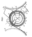
- FIG. 1 shows a schematic, partially sectioned representation Transfer suction roller 10 with an associated web holding box 12 Functional unit formed is part of a device for treatment a material web 14, which is in particular a paper or Cardboard web can act.
- a stationary one Suction box 20 arranged, its interior with a vacuum source is connected, which may include a blower 22, for example.
- the transfer suction roller 10 has both in the run-up area A and Drainage area B of the material web 14 or between it and the Transfer suction roller 10 felt 16 each one on the inside of the perforated roll shell 18 adjacent suction zone 24 or 26, between which a further suction zone 28 can be provided.
- the suction zones 24, 26, 28 are in the inner circumferential direction of the transfer suction roll 10 each by extending parallel to the roller axis 30, between the stationary suction box 20 and the inside of the roll shell 18 arranged sealing strips 32 to 38 limited.
- the Suction zones 24, 26, 28 each as to the inside of the perforated roll shell 18 open suction chambers formed.
- the outer web holding box arranged after the drainage area B. 12 is via the suction zone 26 provided in the discharge area B. sucked.
- suction zone 24 connected to vacuum source 22 is subjected to vacuum.
- the corresponding load is applied in the direction of web travel L at least behind the suction zone 24 arranged suction zones 28 and 26 partly due to the evacuated jacket holes 40 in particular of the roll shell 18 entrained vacuum.
- the entire vacuum is thus primarily directly with that in the run-up area A provided suction zone 24 connected.
- Intermediate suction zone 28 can, however, with one another via a throttle point 42 be connected, which is formed in the present case in that between the relevant axial sealing strip 34 and the roll shell 18 a corresponding gap is left.
- a variable throttle point can be provided.
- Several such throttling points can also be used be provided.
- the material web 14 through the in the run-up area A provided suction zone 24 of the transfer suction roller 10 from a felt 44 removed, which is guided in front of a roller 46, for example can be assigned to a press.
- the intermediate suction zone 28 serves to the removed from the felt 44 web 14 on the over Transfer suction roller 10 to hold guided felt 16.
- the permeability of the felt 16 Abruptly reduced above the suction zone 24, creating an active vacuum is built up in the intermediate suction zone 28.
- the intermediate suction zone 28 and the suction zone 26 provided in the outlet area B at least partly due to the evacuated jacket holes in particular 14 entrained vacuum applied with a corresponding vacuum become. Air permeability is of particular importance here the felt 16 and the material web 14.
- the two suction zones 24 and 28 are also over the throttle point 42 connected to each other.
- This throttle point 42 can in particular also be variable.
- another can throttled or throttled connection between the two suction zones 24 and 28 may be provided.
- the suction zone 26 provided in the outlet area B which in the present case only begins after this run-off area B serves the particular dragged along via the evacuated jacket holes 40, according to the third sealing strip 36 vacant vacuum to generate the required Exploit negative pressure inside the web holding box 12, so that a separate suction of this web holding box 12 is no longer required is.
- the fourth sealing strip 38 must be provided for this.
- the result Additional chamber-like suction zone 26 formed cooperates with the almost closed interior 48 of the web holding box 12 at the same time as a noise insulation chamber.
- the suction zone 26 can basically also begin before drainage area B. It then extends to act accordingly far above the web holding box 12 Drain area B out.
- the web holding box 12 is trough-shaped and for the transfer suction roll 10 open, the opening area in question by a Seal 50 such as a scraper that can be pressed with compressed air onto the Area of the assigned suction zone 26 of the transfer suction roller 10 is limited is.
- the area between the web holding box 12 and the material web 14 carrying felt 16 is at the rear end in the web running direction L Web holding box 12 sealed by a seal 52, which is for example a non-contact seal or a lip seal can act.
- a non-contact seal can for example in the manner of an air sword by blowing out air be realized diagonally against the felt.
- a lip seal a plastic slat that clings to the felt 16 conceivable.
- the interior 48 of the web holding box 12 can in particular on the end faces contact-free with a small gap due to sealing plates to the felt 16 or to the transfer suction roll 10 or alternatively, for example be sealed with an air sword.
- the negative pressure which arises in the web holding box 12 can, for example via a vacuum breaker such as a vacuum choke in particular or the like to be adjustable.
- the web holding box 12 can in its lower area with a Dirty water drain 54 may be provided, for example a drain pipe or a drain hose can be assigned to the one lower point opens into a water castle or a siphon, so that the interior 48 of the web holding box 12 adjusts itself Negative pressure remains. Is the interior 48 of the web stop box 12 with a vacuum breaker, in particular a vacuum throttle valve or the like connected, this negative pressure can be arbitrary can be set.
- the material web 14 supported by the felt 16 finally fed to a roller 56 wrapped in a felt 64 and, like the roller 46, again assigned to a press, for example can be.
- Figure 2 shows a schematic, partially sectioned representation Press arrangement with two shoe presses, between which the Transfer suction roller 10 and the web holding box 12 comprehensive functional unit 1 is used.
- the material web 14 is in the area of a Suction roller 58 is taken over by an upper felt 60 from a screen belt 62 and then together with a bottom felt 16 a first in Web running direction L extended press nip S1 supplied. In connection then the material web 14 together with the bottom felt 16 over the Transfer suction roller 10 and then a second in the web running direction L extended press nip S2 supplied.
- the two are in the direction of web travel L extended press nips S1 and S2 by two separate, one another Adjacent shoe presses each with one below Shoe press unit 66 or 68 and an opposing roller 46 or 56 formed.
- the material web 14 is preferably designed as a suction roll Deflection roller 70 guided and in the area of another as a suction roller trained deflecting roller 72 taken over by a dryer fabric 38 and the first drying cylinder 76 of a dryer section.
- a top felt 64 is around the counter-roller 56 of the second shoe press 56, 68 out, so that both shoe presses 46, 66 and 56, 68 each felted twice are. Following the second extended press nip S2 Material web 14 in the region of the deflection roller designed as a suction roller 70 again separated from the upper felt 64.
- the web holding box 12 is in the Connection to the transfer suction roller 10 and between this and the counter roller 56 of the subsequent shoe press 56, 68 arranged.
Landscapes
- Paper (AREA)
- Advancing Webs (AREA)
Abstract
Description
- Figur 1
- eine schematische, teilweise geschnittene Darstellung einer Transfersaugwalze mit zugeordnetem Bahnhaltekasten und
- Figur 2
- eine schematische, teilweise geschnittene Darstellung einer Pressenanordnung mit zwei Schuhpressen, zwischen denen die eine Transfersaugwalze und einen Bahnhaltekasten umfassende Funktionseinheit gemäß Figur 1 eingesetzt ist.
- 10
- Transfersaugwalze
- 12
- Bahnhaltekasten
- 14
- Materialbahn
- 16
- poröses Stützband, Filz
- 18
- gelochter Walzenmantel
- 20
- Saugkasten
- 22
- Vakuumquelle, Gebläse
- 24
- Saugzone im Auflaufbereich
- 26
- Saugzone im Ablaufbereich
- 28
- Zwischensaugzone
- 30
- Walzenachse
- 32
- Dichtleiste
- 34
- Dichtleiste
- 36
- Dichtleiste
- 38
- Dichtleiste
- 40
- Mantellöcher
- 42
- Drosselstelle
- 44
- Filz
- 46
- Walze
- 48
- Innenraum
- 50
- Dichtung
- 52
- Dichtung
- 54
- Schmutzwasserablauf
- 56
- Walze
- 58
- Saugwalze
- 60
- Oberfilz
- 62
- Siebband
- 64
- Oberfilz
- 66
- Schuhpreßeinheit
- 68
- Schuhpreßeinheit
- 70
- Umlenkwalze
- 72
- Umlenkwalze
- 74
- Trockensieb
- 76
- Trockenzylinder
- A
- Auflaufbereich
- B
- Ablaufbereich
- L
- Bahnlaufrichtung
- S1
- verlängerter Preßspalt
- S2
- verlängerter Preßspalt
Claims (16)
- Vorrichtung zur Behandlung einer Materialbahn (14) wie insbesondere einer Papier- oder Kartonbahn, in der die Materialbahn (14) zusammen mit einem porösen Stützband (16) über eine insbesondere als Pick-up- und/oder Transferwalze dienende, einen gelochten Mantel (18) aufweisende Saugwalze (10) geführt ist, wobei das poröse Stützband (16) im Bereich der Saugwalze (10) zwischen dieser und der Materialbahn (14) liegt,
dadurch gekennzeichnet,
daß die Saugwalze (10) sowohl im Auflaufbereich (A) als auch im Ablaufbereich (B) der Materialbahn (14) jeweils eine an die Innenseite des gelochten Walzenmantels (18) angrenzende Saugzone (24 bzw. 26) aufweist, daß die im Auflaufbereich (A) vorgesehene Saugzone (24) mit einer Vakuumquelle (22) verbunden ist, daß ein im Anschluß an den Ablaufbereich (B) angeordneter äußerer Bahnhaltekasten (12) oder Rohrsauger über die im Ablaufbereich (B) vorgesehene Saugzone (26) besaugt ist und daß diese den Bahnhaltekasten (12) bzw. den Rohrsauger beaufschlagende, im Ablaufbereich (B) vorgesehene Saugzone (26) über die im Auflaufbereich (A) vorgesehene, mit der Vakuumquelle (22) verbundene Saugzone (24) mit Vakuum beaufschlagt ist. - Vorrichtung nach Anspruch 1,
dadurch gekennzeichnet,
daß in Bahnlaufrichtung (L) zwischen der im Auflaufbereich (A) und der im Ablaufbereich (B) der Materialbahn (14) vorgesehenen Saugzone (24 bzw. 26) wenigstens eine Zwischensaugzone (28) vorgesehen ist und daß sowohl die Zwischensaugzone (28) als auch die im Ablaufbereich (B) vorgesehene Saugzone (26) über die im Auflaufbereich (A) vorgesehene, mit der Vakuumquelle (22) verbundene Saugzone (24) mit Vakuum beaufschlagt ist. - Vorrichtung nach Anspruch 1 oder 2,
dadurch gekennzeichnet,
daß die Zwischensaugzone (28) und/oder die im Ablaufbereich (B) vorgesehene Saugzone (26) zumindest teilweise durch das insbesondere über die evakuierten Mantellöcher (40) mitgeschleppte Vakuum der Saugwalze (10) mit Vakuum beaufschlagt sind. - Vorrichtung nach einem der vorhergehenden Ansprüche,
dadurch gekennzeichnet,
daß die im Auflaufbereich (A) vorgesehene Saugzone (24) und die in Bahnlaufrichtung (L) darauffolgende Saugzone (28) über wenigstens eine vorzugsweise variable Drosselstelle (42) miteinander verbunden sind. - Vorrichtung nach einem der vorhergehenden Ansprüche,
dadurch gekennzeichnet,
daß zumindest zwischen der im Ablaufbereich (B) vorgesehenen Saugzone (26) und der dieser vorangehenden Saugzone (28) wenigstens eine vorzugsweise variable gedrosselte Verbindung vorgesehen ist. - Vorrichtung nach einem der vorhergehenden Ansprüche,
dadurch gekennzeichnet,
daß die Saugzonen (24, 26, 28) jeweils als zur Innenseite des gelochten Walzenmantels (18) hin offene Saugkammern ausgebildet sind. - Vorrichtung nach einem der vorhergehenden Ansprüche,
dadurch gekennzeichnet,
daß die Saugzonen (24, 26, 28) in Innenumfangsrichtung der Saugwalze (10) jeweils durch sich parallel zur Walzenachse (30) erstreckende, zwischen einem stationären Saugkasten (20) und der Innenseite des Walzenmantels (18) angeordnete Dichtleisten (32, 34, 36, 38) begrenzt sind. - Vorrichtung nach Anspruch 7,
dadurch gekennzeichnet,
daß zur Bildung einer die im Auflaufbereich (A) vorgesehene Saugzone (24) mit der in Bahnlaufrichtung (L) darauffolgenden Saugzone (28) verbindenden Drosselstelle (42) zwischen der betreffenden axialen Dichtleiste (34) und dem Walzenmantel (18) ein Spalt belassen ist. - Vorrichtung nach einem der vorhergehenden Ansprüche,
dadurch gekennzeichnet,
daß der Bahnhaltekasten (12) wannenartig ausgebildet ist. - Vorrichtung nach einem der vorhergehenden Ansprüche,
dadurch gekennzeichnet,
daß der Bahnhaltekasten (12) zur Saugwalze (10) hin offen und der betreffende Öffnungsbereich durch eine entsprechende Dichtung (50) zumindest im wesentlichen auf den Bereich der betreffenden Saugzone (26) der Saugwalze (10) begrenzt ist. - Vorrichtung nach einem der vorhergehenden Ansprüche,
dadurch gekennzeichnet,
daß der Bereich zwischen dem Bahnhaltekasten (12) und dem die Materialbahn (14) tragenden porösen Stützband (16) an dem in Bahnlaufrichtung (L) hinteren Ende des Bahnhaltekasten (12) vorzugsweise durch eine berührungslos wirkende Dichtung (52) oder eine Lippendichtung abgedichtet ist. - Vorrichtung nach einem der vorhergehenden Ansprüche,
dadurch gekennzeichnet,
daß der sich in dem Bahnhaltekasten (12) einstellende Unterdruck vorzugsweise über einen Vakuumbrecher wie insbesondere eine Vakuumdrosselklappe oder dergleichen einstellbar ist. - Vorrichtung nach einem der vorhergehenden Ansprüche,
dadurch gekennzeichnet,
daß der Bahnhaltekasten (12) in seinem unteren Bereich mit einem Schmutzwasserablauf (54) versehen ist, dem vorzugsweise eine Ablaufleitung zugeordnet ist, die an einer tiefer gelegenen Stelle in ein Wasserschloß mündet. - Vorrichtung nach einem der vorhergehenden Ansprüche,
dadurch gekennzeichnet,
daß das poröse Stützband durch einen Filz (16) gebildet ist. - Vorrichtung nach einem der vorhergehenden Ansprüche,
dadurch gekennzeichnet,
daß die Materialbahn (14) durch die im Auflaufbereich (A) vorgesehene Saugzone der Saugwalze (10) von einem Filz (44) abgenommen wird. - Vorrichtung nach einem der vorhergehenden Ansprüche,
dadurch gekennzeichnet,
daß die Saugwalze (10) zwischen zwei Pressen (46, 66; 56, 68) vorgesehen ist.
Applications Claiming Priority (2)
| Application Number | Priority Date | Filing Date | Title |
|---|---|---|---|
| DE19921202A DE19921202A1 (de) | 1998-10-20 | 1999-05-07 | Vorrichtung zur Behandlung einer Materialbahn |
| DE19921202 | 1999-05-07 |
Publications (2)
| Publication Number | Publication Date |
|---|---|
| EP1050621A2 true EP1050621A2 (de) | 2000-11-08 |
| EP1050621A3 EP1050621A3 (de) | 2001-03-28 |
Family
ID=7907379
Family Applications (1)
| Application Number | Title | Priority Date | Filing Date |
|---|---|---|---|
| EP00104997A Withdrawn EP1050621A3 (de) | 1999-05-07 | 2000-03-09 | Vorrichtung zur Behandlung einer Materialbahn |
Country Status (2)
| Country | Link |
|---|---|
| US (1) | US6328194B1 (de) |
| EP (1) | EP1050621A3 (de) |
Cited By (3)
| Publication number | Priority date | Publication date | Assignee | Title |
|---|---|---|---|---|
| WO2005021866A1 (de) * | 2003-08-26 | 2005-03-10 | Voith Paper Patent Gmbh | Bahnführungseinrichtung |
| EP1536061A1 (de) | 2003-11-27 | 2005-06-01 | Voith Paper Patent GmbH | Saug- oder Blaswalze |
| CN101333699B (zh) * | 2007-06-29 | 2011-09-07 | 特鲁菲舍尔股份有限公司及两合公司 | 用于对包含纺织纤维的纤维束进行纤维分选或精选的设备 |
Families Citing this family (8)
| Publication number | Priority date | Publication date | Assignee | Title |
|---|---|---|---|---|
| DE19847799A1 (de) * | 1998-10-16 | 2000-04-20 | Bachofen & Meier Ag Buelach | Zugwalze für bahnförmige Materialien, insbesondere für Papier- oder Kartonbahnen, Kunststoff- oder Metallfolien |
| EP1061026A1 (de) * | 1999-06-16 | 2000-12-20 | E.I. Du Pont De Nemours And Company | Segmentierte Saugwalze |
| US11230453B2 (en) * | 2003-02-18 | 2022-01-25 | Körber Tissue Fold S.R.L. | Roller for conveying a web or sheet of paper in paper converting machines and conveying method thus obtained |
| DE10347177A1 (de) | 2003-10-10 | 2005-05-12 | Voith Paper Patent Gmbh | Saug- oder Balswalze |
| US7955550B2 (en) * | 2007-04-20 | 2011-06-07 | Lrm Industries International, Inc | Method of preparing a molded article |
| TWI349644B (en) * | 2008-09-18 | 2011-10-01 | Ind Tech Res Inst | Suction roller and transporting apparatus using the same |
| TWI367855B (en) * | 2008-09-24 | 2012-07-11 | Apparatus and method for guiding the web position | |
| US20120157279A1 (en) * | 2010-12-20 | 2012-06-21 | Uwe Schneider | Process and Apparatus for Joining Flexible Components |
Family Cites Families (14)
| Publication number | Priority date | Publication date | Assignee | Title |
|---|---|---|---|---|
| US2714342A (en) * | 1950-11-02 | 1955-08-02 | Beloit Iron Works | Suction roll |
| US2748671A (en) * | 1952-01-25 | 1956-06-05 | Beloit Iron Works | Paper-making machines |
| US2869437A (en) * | 1955-09-15 | 1959-01-20 | Beloit Iron Works | Paper machine press section |
| US3587962A (en) * | 1968-12-06 | 1971-06-28 | Agfa Gevaert Ag | Suction cylinder for transmitting a torque |
| US3902960A (en) * | 1972-08-30 | 1975-09-02 | Olinkraft Inc | Water control system for suction rolls in papermaking machines |
| DE2364346C3 (de) | 1973-12-22 | 1978-04-06 | J.M. Voith Gmbh, 7920 Heidenheim | Trockeneinrichtung für Papierbahnen o.dgl |
| FI820776A7 (fi) * | 1982-03-05 | 1983-09-06 | Valmet Oy | Paperikoneen puristinosa. |
| DE3914761A1 (de) * | 1989-03-08 | 1990-11-15 | Voith Gmbh J M | Leitwalze fuer ein poroeses band, beispielsweise fuer ein trockensieb einer papiermaschine |
| DE4008870C2 (de) | 1990-03-20 | 1995-06-01 | Breitenbach Ag Bandfabrik | Verfahren zur kontinuierlichen Entfeuchtung und anschließenden Stauchung eines flächigen Textilgutes wie Gewebe, Gewirke oder unstrukturierten Materials sowie Vorrichtung zur Durchführung des Verfahrens |
| DE4023297A1 (de) * | 1990-07-21 | 1992-01-23 | Voith Gmbh J M | Ein-sieb-trockengruppe |
| DE4436745A1 (de) | 1994-10-14 | 1996-04-18 | Wet Tex Maschinenbau Gmbh | Vorrichtung zum Transportieren und Behandeln einer Warenbahn |
| DE29506620U1 (de) * | 1995-04-19 | 1995-06-08 | Voith Sulzer Papiermaschinen GmbH, 89522 Heidenheim | Saugwalze |
| DE19654282A1 (de) | 1996-12-24 | 1998-06-25 | Voith Sulzer Papiermasch Gmbh | Pressenpartie |
| CA2261085C (en) * | 1999-02-01 | 2005-01-18 | Bowater Pulp And Paper Canada Inc. | High pressure reciprocating suction roll shower |
-
2000
- 2000-03-09 EP EP00104997A patent/EP1050621A3/de not_active Withdrawn
- 2000-05-05 US US09/564,806 patent/US6328194B1/en not_active Expired - Fee Related
Cited By (4)
| Publication number | Priority date | Publication date | Assignee | Title |
|---|---|---|---|---|
| WO2005021866A1 (de) * | 2003-08-26 | 2005-03-10 | Voith Paper Patent Gmbh | Bahnführungseinrichtung |
| EP1536061A1 (de) | 2003-11-27 | 2005-06-01 | Voith Paper Patent GmbH | Saug- oder Blaswalze |
| CN101333699B (zh) * | 2007-06-29 | 2011-09-07 | 特鲁菲舍尔股份有限公司及两合公司 | 用于对包含纺织纤维的纤维束进行纤维分选或精选的设备 |
| CN101333706B (zh) * | 2007-06-29 | 2011-09-14 | 特鲁菲舍尔股份有限公司及两合公司 | 用于纤维整理或纤维选择含纺织纤维的纤维条的设备 |
Also Published As
| Publication number | Publication date |
|---|---|
| EP1050621A3 (de) | 2001-03-28 |
| US6328194B1 (en) | 2001-12-11 |
Similar Documents
| Publication | Publication Date | Title |
|---|---|---|
| DE69429941T2 (de) | Verfahren und Modul zum Trocknen sowie ihre Anwendung in Trockenpartien insbesondere von Hochgeschwindigkeitspapiermaschinen | |
| DE4224730C1 (en) | Tissue paper mfg. machine preventing moisture return - comprises shoe press for press unit(s) for drying tissue web, for min. press units | |
| DE68921355T2 (de) | Verfahren und Vorrichtung in der Trockenpartie mit einzigem Trockentuch einer Papiermaschine und eine Walze zur Anwendung des Verfahrens. | |
| DE8805966U1 (de) | Pressenpartie einer Maschine zur Herstellung einer Faserstoffbahn, insbesondere Papierbahn | |
| DE3216214A1 (de) | Kompakte pressenpartie einer papiermaschine | |
| AT394870B (de) | Trocknungsvorrichtung | |
| DE2331313B2 (de) | Langsieb-papiermaschine | |
| EP0608534B1 (de) | Nasspresse für eine Papiermaschine | |
| AT400856B (de) | Vorrichtung zum überführen einer faserstoffbahn | |
| DE19602697B4 (de) | Trockenpartie | |
| EP0954634B1 (de) | Pressenanordnung | |
| DE19921202A1 (de) | Vorrichtung zur Behandlung einer Materialbahn | |
| DE102018124016A1 (de) | Vorrichtung und Verfahren zur Entwässerung einer Faserstoffbahn | |
| EP2454412A1 (de) | Vorrichtung zur herstellung einer faserstoffbahn | |
| DE1461135A1 (de) | Nasspressenteil fuer Papiermaschinen | |
| DE4334143C1 (de) | Pressenpartie einer Papiermaschine mit geschlossener Bahnführung | |
| DE4335024C2 (de) | Pressenpartie einer Papiermaschine und Überführeinrichtung | |
| EP1420111B1 (de) | Pressenanordnung | |
| AT3189U1 (de) | Saugwalzenanordnung für die presse einer zellstofftrockenmaschine | |
| DE19728824A1 (de) | Saugwalze für eine Papiermaschine | |
| DE10137095A1 (de) | Maschine zur Herstellung einer Faserstoffbahn | |
| AT521368B1 (de) | Vorrichtung und verfahren zum überführen eines streifens einer bahn | |
| DE3731541A1 (de) | Verfahren und vorrichtung zur stabilisierten fuehrung einer bewegten materialbahn | |
| EP1673505B1 (de) | Saug- oder blaswalze | |
| DE1461135C (de) | Naßpresse für Papiermaschinen |
Legal Events
| Date | Code | Title | Description |
|---|---|---|---|
| PUAI | Public reference made under article 153(3) epc to a published international application that has entered the european phase |
Free format text: ORIGINAL CODE: 0009012 |
|
| AK | Designated contracting states |
Kind code of ref document: A2 Designated state(s): AT BE CH CY DE DK ES FI FR GB GR IE IT LI LU MC NL PT SE |
|
| AX | Request for extension of the european patent |
Free format text: AL;LT;LV;MK;RO;SI |
|
| RAP1 | Party data changed (applicant data changed or rights of an application transferred) |
Owner name: VOITH PAPER PATENT GMBH |
|
| PUAL | Search report despatched |
Free format text: ORIGINAL CODE: 0009013 |
|
| AK | Designated contracting states |
Kind code of ref document: A3 Designated state(s): AT BE CH CY DE DK ES FI FR GB GR IE IT LI LU MC NL PT SE |
|
| AX | Request for extension of the european patent |
Free format text: AL;LT;LV;MK;RO;SI |
|
| 17P | Request for examination filed |
Effective date: 20010928 |
|
| AKX | Designation fees paid |
Free format text: DE FI SE |
|
| GRAP | Despatch of communication of intention to grant a patent |
Free format text: ORIGINAL CODE: EPIDOSNIGR1 |
|
| STAA | Information on the status of an ep patent application or granted ep patent |
Free format text: STATUS: THE APPLICATION IS DEEMED TO BE WITHDRAWN |
|
| 18D | Application deemed to be withdrawn |
Effective date: 20051005 |