EP1050341A2 - Röhrenelektrofilter mit beweglichen Elektroden - Google Patents
Röhrenelektrofilter mit beweglichen Elektroden Download PDFInfo
- Publication number
- EP1050341A2 EP1050341A2 EP00109289A EP00109289A EP1050341A2 EP 1050341 A2 EP1050341 A2 EP 1050341A2 EP 00109289 A EP00109289 A EP 00109289A EP 00109289 A EP00109289 A EP 00109289A EP 1050341 A2 EP1050341 A2 EP 1050341A2
- Authority
- EP
- European Patent Office
- Prior art keywords
- electrodes
- tubular
- precipitation
- electrode
- shaped
- Prior art date
- Legal status (The legal status is an assumption and is not a legal conclusion. Google has not performed a legal analysis and makes no representation as to the accuracy of the status listed.)
- Granted
Links
Images

Classifications
-
- B—PERFORMING OPERATIONS; TRANSPORTING
- B03—SEPARATION OF SOLID MATERIALS USING LIQUIDS OR USING PNEUMATIC TABLES OR JIGS; MAGNETIC OR ELECTROSTATIC SEPARATION OF SOLID MATERIALS FROM SOLID MATERIALS OR FLUIDS; SEPARATION BY HIGH-VOLTAGE ELECTRIC FIELDS
- B03C—MAGNETIC OR ELECTROSTATIC SEPARATION OF SOLID MATERIALS FROM SOLID MATERIALS OR FLUIDS; SEPARATION BY HIGH-VOLTAGE ELECTRIC FIELDS
- B03C3/00—Separating dispersed particles from gases or vapour, e.g. air, by electrostatic effect
- B03C3/02—Plant or installations having external electricity supply
- B03C3/04—Plant or installations having external electricity supply dry type
- B03C3/06—Plant or installations having external electricity supply dry type characterised by presence of stationary tube electrodes
-
- B—PERFORMING OPERATIONS; TRANSPORTING
- B03—SEPARATION OF SOLID MATERIALS USING LIQUIDS OR USING PNEUMATIC TABLES OR JIGS; MAGNETIC OR ELECTROSTATIC SEPARATION OF SOLID MATERIALS FROM SOLID MATERIALS OR FLUIDS; SEPARATION BY HIGH-VOLTAGE ELECTRIC FIELDS
- B03C—MAGNETIC OR ELECTROSTATIC SEPARATION OF SOLID MATERIALS FROM SOLID MATERIALS OR FLUIDS; SEPARATION BY HIGH-VOLTAGE ELECTRIC FIELDS
- B03C3/00—Separating dispersed particles from gases or vapour, e.g. air, by electrostatic effect
- B03C3/34—Constructional details or accessories or operation thereof
- B03C3/40—Electrode constructions
- B03C3/41—Ionising-electrodes
-
- B—PERFORMING OPERATIONS; TRANSPORTING
- B03—SEPARATION OF SOLID MATERIALS USING LIQUIDS OR USING PNEUMATIC TABLES OR JIGS; MAGNETIC OR ELECTROSTATIC SEPARATION OF SOLID MATERIALS FROM SOLID MATERIALS OR FLUIDS; SEPARATION BY HIGH-VOLTAGE ELECTRIC FIELDS
- B03C—MAGNETIC OR ELECTROSTATIC SEPARATION OF SOLID MATERIALS FROM SOLID MATERIALS OR FLUIDS; SEPARATION BY HIGH-VOLTAGE ELECTRIC FIELDS
- B03C3/00—Separating dispersed particles from gases or vapour, e.g. air, by electrostatic effect
- B03C3/34—Constructional details or accessories or operation thereof
- B03C3/74—Cleaning the electrodes
-
- B—PERFORMING OPERATIONS; TRANSPORTING
- B03—SEPARATION OF SOLID MATERIALS USING LIQUIDS OR USING PNEUMATIC TABLES OR JIGS; MAGNETIC OR ELECTROSTATIC SEPARATION OF SOLID MATERIALS FROM SOLID MATERIALS OR FLUIDS; SEPARATION BY HIGH-VOLTAGE ELECTRIC FIELDS
- B03C—MAGNETIC OR ELECTROSTATIC SEPARATION OF SOLID MATERIALS FROM SOLID MATERIALS OR FLUIDS; SEPARATION BY HIGH-VOLTAGE ELECTRIC FIELDS
- B03C3/00—Separating dispersed particles from gases or vapour, e.g. air, by electrostatic effect
- B03C3/34—Constructional details or accessories or operation thereof
- B03C3/86—Electrode-carrying means
-
- B—PERFORMING OPERATIONS; TRANSPORTING
- B03—SEPARATION OF SOLID MATERIALS USING LIQUIDS OR USING PNEUMATIC TABLES OR JIGS; MAGNETIC OR ELECTROSTATIC SEPARATION OF SOLID MATERIALS FROM SOLID MATERIALS OR FLUIDS; SEPARATION BY HIGH-VOLTAGE ELECTRIC FIELDS
- B03C—MAGNETIC OR ELECTROSTATIC SEPARATION OF SOLID MATERIALS FROM SOLID MATERIALS OR FLUIDS; SEPARATION BY HIGH-VOLTAGE ELECTRIC FIELDS
- B03C2201/00—Details of magnetic or electrostatic separation
- B03C2201/10—Ionising electrode with two or more serrated ends or sides
Definitions
- the invention relates to a tubular electrostatic precipitator with at least one tubular precipitation electrode and each a coaxially arranged wire or rod Outflow electrode.
- Electrostatic filters usually consist of a on 35 to 75 kV charged spray electrode, which is a grounded Precipitation electrode at an appropriate distance faces.
- the precipitation electrode must be sufficient large surface area for the precipitation of the filtered dust particles have and is mostly with a device for shaking of precipitation. Due to the high The gas flowing through is ionized, whereby in the electric force field between the two electrodes a directed Stream of negative gas ions towards the grounded Hiking tube. If by such an electrostatic precipitator Pumped gas with solid or liquid suspended particles is bombarded by the ions and charged also negative. As a result of the electric field the charged particles are driven towards the precipitation electrode.
- tubular electrostatic precipitators in which a wire-shaped Outflow electrode is surrounded by a grounded cylinder also other designs, such as plate electrostatic precipitators, known.
- the invention now aims to provide a tubular electrostatic precipitator to create of the type mentioned, which also for the use in bio-firing systems is suitable and in can be cleaned mechanically in a particularly simple manner.
- the tube electrostatic filter according to the invention solves this problem formed so that the discharge electrode on a pivotable or slidable holding part is fixed and from the position coaxial to the precipitation electrode into one of the Inner wall of the tubular precipitation electrode adjacent Position is displaceable or pivotable.
- the discharge electrode which are designed as wire or rope can be moved or pivoted in a suitable manner can and in one of the inner wall of the tubular precipitation electrode neighboring location can be spent in the now released clear cross section of the precipitation electrode a corresponding cleaning device, for example a pipe brush or the like, are introduced and efficient quick cleaning.
- a corresponding cleaning device for example a pipe brush or the like
- the design according to the invention is particularly advantageous made so that a plurality of cylindrical Precipitation electrodes in a common housing is arranged, at the lower end of which a dust hopper is connected is and that the discharge electrodes on a common Holding part fixed and slidable or pivotable with this are arranged.
- Such a design is particularly advantageous taken so that the axes of the cylindrical electrodes on the circumference of at least one circle in the same Pitch angles are arranged to each other and that the common holding part is star-shaped, the Length of the arms from the center of the star-shaped part to Clamping point of the outflow electrodes the radius of the circle corresponds and the star-shaped holding part around the axis of the Circle is pivotable, such training in constructively simple way of pivoting the joint Outflow electrodes to release the light to be cleaned Cross-section of the precipitation electrodes allows.
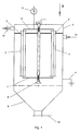
- FIG. 1 shows a schematic side view a device according to the invention
- Fig. 2 is a plan view 1 in the direction of arrow II of FIG modified training with the cover of the device removed according to Fig. 1.
- Fig. 1 is a plurality of tubular in a housing 1 or cylindrical precipitation electrodes 2 arranged. Each coaxial to the axis of the tubular precipitation electrodes wires 3 are tensioned, which are the outflow electrodes form.
- the tubular precipitation electrodes are grounded together with the housing 1 via a line 4, whereas the outflow electrodes 3 with a high voltage source 5 are connected.
- the outflow electrodes 3 are on one common carrier or holding part 6 set, the lower ends of these discharge electrodes to a corresponding one Brackets 7 are set.
- the counter holder 7 is relative to Housing 1 stored in a bearing 8.
- the lower end of the housing is funnel-shaped Mouth 9, which can be closed by a slide 10.
- the falling one collects in this funnel-shaped mouth 9 Dust, which is removed by opening the slide 10 can be.
- the tubular or cylindrical deposition or precipitation electrodes 2 corresponding amounts of solids, which are removed by mechanical cleaning have to.
- the upper holding part 6 is for the outflow electrodes 3 are star-shaped and around one Axis 11 pivotally mounted.
- the pivoting can be in the sense of the double arrow 12 such that the outflow electrodes 3 in the vicinity of the inner wall 13 of the precipitation electrodes 2 can be pivoted.
- the carrier or holding part 6 can hiebei all outflow electrodes at the same time 3 pivoted into such a non-operational position so that the complete clear cross-section of the separating electrodes 2 for mechanical cleaning, for example by means of brushes.
Landscapes
- Electrostatic Separation (AREA)
- Separation Using Semi-Permeable Membranes (AREA)
Abstract
Description
Claims (3)
- Röhrenelektrofilter mit wenigstens einer rohrförmigen Niederschlagselektrode und jeweils einer koaxial angeordneten draht- oder stabförmigen Ausströmelektrode, dadurch gekennzeichnet, daß die Ausströmelektrode an einem verschwenkbaren oder verschiebbaren Halteteil festgelegt ist und aus der zur Niederschlagselektrode koaxialen Lage in eine der Innenwand der rohrförmigen Niederschlagselektrode benachbarte Lage verschieb- oder verschwenkbar ist.
- Röhrenelektrofilter nach Anspruch 1, dadurch gekennzeichnet, daß eine Mehrzahl von zylinderförmigen Niederschlagselektroden in einem gemeinsamen Gehäuse angeordnet ist, an dessen unterem Ende ein Staubtrichter angeschlossen ist und daß die Ausströmelektroden auf einem gemeinsamen Halteteil festgelegt und mit diesem verschieb- oder verschwenkbar angeordnet sind.
- Röhrenelektrofilter nach Anspruch 2, dadurch gekennzeichnet, daß die Achsen der zylinderförmigen Elektroden am Umfang wenigstens eines Kreises in gleichen Teilungswinkeln zueinander angeordnet sind und daß der gemeinsame Halteteil sternförmig ausgebildet ist, wobei die Länge der Arme vom Mittelpunkt des sternförmigen Teils bis zur Einspannstelle der Ausströmelektroden dem Radius des Kreises entspricht und der sternförmige Halteteil um die Achse des Kreises verschwenkbar ist.
Priority Applications (1)
| Application Number | Priority Date | Filing Date | Title |
|---|---|---|---|
| AT00109289T ATE316824T1 (de) | 1999-05-03 | 2000-04-29 | Röhrenelektrofilter mit beweglichen elektroden |
Applications Claiming Priority (2)
| Application Number | Priority Date | Filing Date | Title |
|---|---|---|---|
| AT0078699A AT408846B (de) | 1999-05-03 | 1999-05-03 | Röhrenelektrofilter |
| AT78699 | 1999-11-12 |
Publications (3)
| Publication Number | Publication Date |
|---|---|
| EP1050341A2 true EP1050341A2 (de) | 2000-11-08 |
| EP1050341A3 EP1050341A3 (de) | 2001-01-17 |
| EP1050341B1 EP1050341B1 (de) | 2006-02-01 |
Family
ID=3499723
Family Applications (1)
| Application Number | Title | Priority Date | Filing Date |
|---|---|---|---|
| EP00109289A Expired - Lifetime EP1050341B1 (de) | 1999-05-03 | 2000-04-29 | Röhrenelektrofilter mit beweglichen Elektroden |
Country Status (3)
| Country | Link |
|---|---|
| EP (1) | EP1050341B1 (de) |
| AT (2) | AT408846B (de) |
| DE (1) | DE50012144D1 (de) |
Cited By (5)
| Publication number | Priority date | Publication date | Assignee | Title |
|---|---|---|---|---|
| EP2065094A2 (de) | 2007-11-27 | 2009-06-03 | Jörg Meister | Elektrofilter |
| EP2036615A3 (de) * | 2007-09-13 | 2010-02-17 | Peter Buchta | Elektrofilter für eine Feuerungsanlage |
| US8257469B2 (en) * | 2009-03-18 | 2012-09-04 | Meister Environment Technology Ltd. | Electrostatic filter |
| EP1967273A3 (de) * | 2007-03-05 | 2013-10-16 | Schmatloch Nückel Technologietransfer | Elektrofilter für eine Kleinfeuerungsanlage |
| CN107684977A (zh) * | 2017-08-30 | 2018-02-13 | 珠海格力电器股份有限公司 | 一种电净化结构及包含其的空气净化装置 |
Families Citing this family (4)
| Publication number | Priority date | Publication date | Assignee | Title |
|---|---|---|---|---|
| DE202007004263U1 (de) | 2007-02-16 | 2007-07-05 | Otto Spanner Gmbh | Elektrofilter |
| DE102007061199B4 (de) * | 2007-12-16 | 2010-02-11 | Elituus Ltd. & Co. Kg | Kraftwerksanlage und Verfahren zur Behandlung von Prozessluft aus Kraftwerkanlagen |
| US11635231B2 (en) | 2019-09-03 | 2023-04-25 | Sl-Technik Gmbh | Rotating grate with a cleaning device for a biomass heating system |
| KR102836898B1 (ko) * | 2022-06-17 | 2025-07-23 | 이앤엠 주식회사 | 배기덕트 없이 미세먼지 및 악취물질을 제거할 수 있는 집진장치 |
Family Cites Families (5)
| Publication number | Priority date | Publication date | Assignee | Title |
|---|---|---|---|---|
| US2443662A (en) * | 1945-12-29 | 1948-06-22 | Westinghouse Electric Corp | Electrostatic dust precipitator |
| SE452956B (sv) * | 1984-11-05 | 1988-01-04 | Flaekt Ab | For ett flertal emissionselektroder avsedd fasthallningsanordning |
| AT394664B (de) * | 1989-05-02 | 1992-05-25 | Scheuch Alois Gmbh | Elektro-schuettschichtfilter-anlage |
| DE3915639C1 (de) * | 1989-05-12 | 1991-01-24 | Boehler Abfall-Abluft-Abwasser-Umweltschutz Ges.M.B.H., Feldkirch, At | |
| JPH10151363A (ja) * | 1996-11-26 | 1998-06-09 | Shinwa Corp | 多重筒型電気集塵装置 |
-
1999
- 1999-05-03 AT AT0078699A patent/AT408846B/de not_active IP Right Cessation
-
2000
- 2000-04-29 DE DE50012144T patent/DE50012144D1/de not_active Expired - Lifetime
- 2000-04-29 AT AT00109289T patent/ATE316824T1/de not_active IP Right Cessation
- 2000-04-29 EP EP00109289A patent/EP1050341B1/de not_active Expired - Lifetime
Cited By (5)
| Publication number | Priority date | Publication date | Assignee | Title |
|---|---|---|---|---|
| EP1967273A3 (de) * | 2007-03-05 | 2013-10-16 | Schmatloch Nückel Technologietransfer | Elektrofilter für eine Kleinfeuerungsanlage |
| EP2036615A3 (de) * | 2007-09-13 | 2010-02-17 | Peter Buchta | Elektrofilter für eine Feuerungsanlage |
| EP2065094A2 (de) | 2007-11-27 | 2009-06-03 | Jörg Meister | Elektrofilter |
| US8257469B2 (en) * | 2009-03-18 | 2012-09-04 | Meister Environment Technology Ltd. | Electrostatic filter |
| CN107684977A (zh) * | 2017-08-30 | 2018-02-13 | 珠海格力电器股份有限公司 | 一种电净化结构及包含其的空气净化装置 |
Also Published As
| Publication number | Publication date |
|---|---|
| ATE316824T1 (de) | 2006-02-15 |
| DE50012144D1 (de) | 2006-04-13 |
| AT408846B (de) | 2002-03-25 |
| ATA78699A (de) | 2001-08-15 |
| EP1050341A3 (de) | 2001-01-17 |
| EP1050341B1 (de) | 2006-02-01 |
Similar Documents
| Publication | Publication Date | Title |
|---|---|---|
| EP2343130A1 (de) | Vorrichtung zum Abscheiden von Lack-Overspray | |
| DE202007004263U1 (de) | Elektrofilter | |
| EP1050341A2 (de) | Röhrenelektrofilter mit beweglichen Elektroden | |
| AT408843B (de) | Staubfilter | |
| DE3626002C2 (de) | ||
| DE102011052946A1 (de) | Elektroabscheider | |
| EP2189223A1 (de) | Nass abreinigender Elektrofilter zur Abgasreinigung sowie ein hierfür geeignetes Verfahren | |
| EP2062649B1 (de) | Elektrostatischer Abscheider mit Partikelabweisemittel, Heizungssystem und Verfahren zum Betrieb | |
| DE425039C (de) | Verfahren zur elektrischen Reinigung von Gasen | |
| EP2108457A2 (de) | Schornsteinsystem mit Elektrostaubfilter | |
| DE202019101213U1 (de) | Elektrostatische Partikelabscheidevorrichtung | |
| AT393969B (de) | Verfahren zur abreinigung der ionisationselektroden und des rohgasraumes bei einer elektro-schuettschichtfilter-anlage sowie eine anlage, bei welcher das besagte verfahren zur anwendung kommt | |
| EP3025785B1 (de) | Vorrichtung und verfahren zum reinigen von rauchgas einer metallurgischen anlage | |
| DE3230709A1 (de) | Staubzyklon und verfahren zum betrieb eines solchen staubzyklons | |
| EP0352451A2 (de) | Elektrofilter | |
| DE588707C (de) | Vorrichtung zur elektrischen Abscheidung und Rueckgewinnung von staubfoermigen Stoffen aus Gasen | |
| DE102006009765B4 (de) | Röhrenelektrofilter | |
| DE19613720C2 (de) | Staubabscheidevorrichtung und Verfahren zum Staubabscheiden für einen Elektrofilter | |
| DE1557110A1 (de) | Vorrichtung zum Reinigen eines Gases von darin mitgefuehrten Stoffteilchen,insbesondere Feststoffteilchen | |
| DE19823342C2 (de) | Elektrofilter | |
| DE939990C (de) | Reibungselektrofilter | |
| DE347364C (de) | Vorrichtung zum Abblasen des Staubes von den Ausstrahlungs- und Sammelelektroden elektrischer Gasreinigungsanlagen | |
| DE739257C (de) | Elektrischer Gasreiniger | |
| DE2428046B2 (de) | Gasentnahmeeinrichtung | |
| DE202019101212U1 (de) | Gehäusekomponente für eine elektrostatische Partikelabscheidevorrichtung sowie elektrostatische Partikelabscheidevorrichtung |
Legal Events
| Date | Code | Title | Description |
|---|---|---|---|
| PUAI | Public reference made under article 153(3) epc to a published international application that has entered the european phase |
Free format text: ORIGINAL CODE: 0009012 |
|
| AK | Designated contracting states |
Kind code of ref document: A2 Designated state(s): AT BE CH CY DE DK ES FI FR GB GR IE IT LI LU MC NL PT SE |
|
| AX | Request for extension of the european patent |
Free format text: AL;LT;LV;MK;RO;SI |
|
| PUAL | Search report despatched |
Free format text: ORIGINAL CODE: 0009013 |
|
| AK | Designated contracting states |
Kind code of ref document: A3 Designated state(s): AT BE CH CY DE DK ES FI FR GB GR IE IT LI LU MC NL PT SE |
|
| AX | Request for extension of the european patent |
Free format text: AL;LT;LV;MK;RO;SI |
|
| RIC1 | Information provided on ipc code assigned before grant |
Free format text: 7B 03C 3/74 A, 7B 03C 3/86 B, 7B 03C 3/06 B, 7B 03C 3/41 B |
|
| 17P | Request for examination filed |
Effective date: 20010208 |
|
| AKX | Designation fees paid |
Free format text: AT BE CH CY DE DK ES FI FR GB GR IE IT LI LU MC NL PT SE |
|
| 17Q | First examination report despatched |
Effective date: 20030521 |
|
| GRAP | Despatch of communication of intention to grant a patent |
Free format text: ORIGINAL CODE: EPIDOSNIGR1 |
|
| GRAS | Grant fee paid |
Free format text: ORIGINAL CODE: EPIDOSNIGR3 |
|
| GRAA | (expected) grant |
Free format text: ORIGINAL CODE: 0009210 |
|
| AK | Designated contracting states |
Kind code of ref document: B1 Designated state(s): AT BE CH CY DE DK ES FI FR GB GR IE IT LI LU MC NL PT SE |
|
| PG25 | Lapsed in a contracting state [announced via postgrant information from national office to epo] |
Ref country code: IT Free format text: LAPSE BECAUSE OF FAILURE TO SUBMIT A TRANSLATION OF THE DESCRIPTION OR TO PAY THE FEE WITHIN THE PRE;WARNING: LAPSES OF ITALIAN PATENTS WITH EFFECTIVE DATE BEFORE 2007 MAY HAVE OCCURRED AT ANY TIME BEFORE 2007. THE CORRECT EFFECTIVE DATE MAY BE DIFFERENT FROM THE ONE RECORDED.SCRIBED TIME-LIMIT Effective date: 20060201 Ref country code: NL Free format text: LAPSE BECAUSE OF FAILURE TO SUBMIT A TRANSLATION OF THE DESCRIPTION OR TO PAY THE FEE WITHIN THE PRESCRIBED TIME-LIMIT Effective date: 20060201 Ref country code: IE Free format text: LAPSE BECAUSE OF FAILURE TO SUBMIT A TRANSLATION OF THE DESCRIPTION OR TO PAY THE FEE WITHIN THE PRESCRIBED TIME-LIMIT Effective date: 20060201 Ref country code: FI Free format text: LAPSE BECAUSE OF FAILURE TO SUBMIT A TRANSLATION OF THE DESCRIPTION OR TO PAY THE FEE WITHIN THE PRESCRIBED TIME-LIMIT Effective date: 20060201 Ref country code: GB Free format text: LAPSE BECAUSE OF FAILURE TO SUBMIT A TRANSLATION OF THE DESCRIPTION OR TO PAY THE FEE WITHIN THE PRESCRIBED TIME-LIMIT Effective date: 20060201 |
|
| REG | Reference to a national code |
Ref country code: GB Ref legal event code: FG4D Free format text: NOT ENGLISH |
|
| REG | Reference to a national code |
Ref country code: CH Ref legal event code: EP |
|
| REG | Reference to a national code |
Ref country code: IE Ref legal event code: FG4D Free format text: LANGUAGE OF EP DOCUMENT: GERMAN |
|
| REF | Corresponds to: |
Ref document number: 50012144 Country of ref document: DE Date of ref document: 20060413 Kind code of ref document: P |
|
| PG25 | Lapsed in a contracting state [announced via postgrant information from national office to epo] |
Ref country code: AT Free format text: LAPSE BECAUSE OF NON-PAYMENT OF DUE FEES Effective date: 20060429 |
|
| PG25 | Lapsed in a contracting state [announced via postgrant information from national office to epo] |
Ref country code: MC Free format text: LAPSE BECAUSE OF NON-PAYMENT OF DUE FEES Effective date: 20060430 |
|
| PG25 | Lapsed in a contracting state [announced via postgrant information from national office to epo] |
Ref country code: SE Free format text: LAPSE BECAUSE OF FAILURE TO SUBMIT A TRANSLATION OF THE DESCRIPTION OR TO PAY THE FEE WITHIN THE PRESCRIBED TIME-LIMIT Effective date: 20060501 Ref country code: DK Free format text: LAPSE BECAUSE OF FAILURE TO SUBMIT A TRANSLATION OF THE DESCRIPTION OR TO PAY THE FEE WITHIN THE PRESCRIBED TIME-LIMIT Effective date: 20060501 |
|
| PG25 | Lapsed in a contracting state [announced via postgrant information from national office to epo] |
Ref country code: ES Free format text: LAPSE BECAUSE OF FAILURE TO SUBMIT A TRANSLATION OF THE DESCRIPTION OR TO PAY THE FEE WITHIN THE PRESCRIBED TIME-LIMIT Effective date: 20060512 |
|
| NLV1 | Nl: lapsed or annulled due to failure to fulfill the requirements of art. 29p and 29m of the patents act | ||
| PG25 | Lapsed in a contracting state [announced via postgrant information from national office to epo] |
Ref country code: PT Free format text: LAPSE BECAUSE OF FAILURE TO SUBMIT A TRANSLATION OF THE DESCRIPTION OR TO PAY THE FEE WITHIN THE PRESCRIBED TIME-LIMIT Effective date: 20060703 |
|
| GBV | Gb: ep patent (uk) treated as always having been void in accordance with gb section 77(7)/1977 [no translation filed] |
Effective date: 20060201 |
|
| REG | Reference to a national code |
Ref country code: IE Ref legal event code: FD4D |
|
| PLBE | No opposition filed within time limit |
Free format text: ORIGINAL CODE: 0009261 |
|
| STAA | Information on the status of an ep patent application or granted ep patent |
Free format text: STATUS: NO OPPOSITION FILED WITHIN TIME LIMIT |
|
| 26N | No opposition filed |
Effective date: 20061103 |
|
| EN | Fr: translation not filed | ||
| PG25 | Lapsed in a contracting state [announced via postgrant information from national office to epo] |
Ref country code: GR Free format text: LAPSE BECAUSE OF FAILURE TO SUBMIT A TRANSLATION OF THE DESCRIPTION OR TO PAY THE FEE WITHIN THE PRESCRIBED TIME-LIMIT Effective date: 20060502 Ref country code: FR Free format text: LAPSE BECAUSE OF FAILURE TO SUBMIT A TRANSLATION OF THE DESCRIPTION OR TO PAY THE FEE WITHIN THE PRESCRIBED TIME-LIMIT Effective date: 20070323 |
|
| PG25 | Lapsed in a contracting state [announced via postgrant information from national office to epo] |
Ref country code: LU Free format text: LAPSE BECAUSE OF NON-PAYMENT OF DUE FEES Effective date: 20060429 |
|
| PG25 | Lapsed in a contracting state [announced via postgrant information from national office to epo] |
Ref country code: FR Free format text: LAPSE BECAUSE OF FAILURE TO SUBMIT A TRANSLATION OF THE DESCRIPTION OR TO PAY THE FEE WITHIN THE PRESCRIBED TIME-LIMIT Effective date: 20060430 |
|
| PG25 | Lapsed in a contracting state [announced via postgrant information from national office to epo] |
Ref country code: CY Free format text: LAPSE BECAUSE OF FAILURE TO SUBMIT A TRANSLATION OF THE DESCRIPTION OR TO PAY THE FEE WITHIN THE PRESCRIBED TIME-LIMIT Effective date: 20060201 Ref country code: FR Free format text: LAPSE BECAUSE OF FAILURE TO SUBMIT A TRANSLATION OF THE DESCRIPTION OR TO PAY THE FEE WITHIN THE PRESCRIBED TIME-LIMIT Effective date: 20060201 |
|
| PGFP | Annual fee paid to national office [announced via postgrant information from national office to epo] |
Ref country code: BE Payment date: 20081203 Year of fee payment: 9 |
|
| BERE | Be: lapsed |
Owner name: FORSTHUBER, PAUL Effective date: 20090430 |
|
| PG25 | Lapsed in a contracting state [announced via postgrant information from national office to epo] |
Ref country code: BE Free format text: LAPSE BECAUSE OF NON-PAYMENT OF DUE FEES Effective date: 20090430 |
|
| REG | Reference to a national code |
Ref country code: CH Ref legal event code: PUE Owner name: APF ADVANCED PARTICLE FILTERS GMBH Free format text: FORSTHUBER, PAUL#NIEDERALM 78#A-5081 ANIF (AT) -TRANSFER TO- APF ADVANCED PARTICLE FILTERS GMBH#HANNAKSTRASSE 3A#5023 SALZBURG-GNIGL (AT) Ref country code: CH Ref legal event code: NV Representative=s name: OK PAT AG PATENTE MARKEN LIZENZEN |
|
| REG | Reference to a national code |
Ref country code: DE Ref legal event code: R081 Ref document number: 50012144 Country of ref document: DE Owner name: APF ADVANCED PARTICLE FILTERS GMBH, AT Free format text: FORMER OWNER: FORSTHUBER, PAUL, ANIF, AT Effective date: 20130107 |
|
| PGFP | Annual fee paid to national office [announced via postgrant information from national office to epo] |
Ref country code: DE Payment date: 20160830 Year of fee payment: 17 |
|
| REG | Reference to a national code |
Ref country code: DE Ref legal event code: R119 Ref document number: 50012144 Country of ref document: DE |
|
| REG | Reference to a national code |
Ref country code: CH Ref legal event code: PL |
|
| PG25 | Lapsed in a contracting state [announced via postgrant information from national office to epo] |
Ref country code: DE Free format text: LAPSE BECAUSE OF NON-PAYMENT OF DUE FEES Effective date: 20171103 |
|
| REG | Reference to a national code |
Ref country code: CH Ref legal event code: AECN Free format text: DAS PATENT IST AUFGRUND DES WEITERBEHANDLUNGSANTRAGS VOM 23.01.2018 REAKTIVIERT WORDEN. |
|
| PG25 | Lapsed in a contracting state [announced via postgrant information from national office to epo] |
Ref country code: LI Free format text: LAPSE BECAUSE OF NON-PAYMENT OF DUE FEES Effective date: 20170430 Ref country code: CH Free format text: LAPSE BECAUSE OF NON-PAYMENT OF DUE FEES Effective date: 20170430 |
|
| PG25 | Lapsed in a contracting state [announced via postgrant information from national office to epo] |
Ref country code: CH Free format text: LAPSE BECAUSE OF NON-PAYMENT OF DUE FEES Effective date: 20170430 Ref country code: LI Free format text: LAPSE BECAUSE OF NON-PAYMENT OF DUE FEES Effective date: 20170430 |
|
| PGRI | Patent reinstated in contracting state [announced from national office to epo] |
Ref country code: LI Effective date: 20180124 Ref country code: CH Effective date: 20180124 |
|
| REG | Reference to a national code |
Ref country code: DE Ref legal event code: R124 Ref document number: 50012144 Country of ref document: DE |
|
| PGFP | Annual fee paid to national office [announced via postgrant information from national office to epo] |
Ref country code: CH Payment date: 20190604 Year of fee payment: 20 |
|
| REG | Reference to a national code |
Ref country code: CH Ref legal event code: PL |