EP1048930A2 - Faseroptischer Kreisel - Google Patents
Faseroptischer Kreisel Download PDFInfo
- Publication number
- EP1048930A2 EP1048930A2 EP00303550A EP00303550A EP1048930A2 EP 1048930 A2 EP1048930 A2 EP 1048930A2 EP 00303550 A EP00303550 A EP 00303550A EP 00303550 A EP00303550 A EP 00303550A EP 1048930 A2 EP1048930 A2 EP 1048930A2
- Authority
- EP
- European Patent Office
- Prior art keywords
- assembly
- spool
- interconnection
- parts
- ring
- Prior art date
- Legal status (The legal status is an assumption and is not a legal conclusion. Google has not performed a legal analysis and makes no representation as to the accuracy of the status listed.)
- Withdrawn
Links
Images
Classifications
-
- G—PHYSICS
- G01—MEASURING; TESTING
- G01C—MEASURING DISTANCES, LEVELS OR BEARINGS; SURVEYING; NAVIGATION; GYROSCOPIC INSTRUMENTS; PHOTOGRAMMETRY OR VIDEOGRAMMETRY
- G01C19/00—Gyroscopes; Turn-sensitive devices using vibrating masses; Turn-sensitive devices without moving masses; Measuring angular rate using gyroscopic effects
- G01C19/58—Turn-sensitive devices without moving masses
- G01C19/64—Gyrometers using the Sagnac effect, i.e. rotation-induced shifts between counter-rotating electromagnetic beams
- G01C19/72—Gyrometers using the Sagnac effect, i.e. rotation-induced shifts between counter-rotating electromagnetic beams with counter-rotating light beams in a passive ring, e.g. fibre laser gyrometers
- G01C19/721—Details, e.g. optical or electronical details
- G01C19/722—Details, e.g. optical or electronical details of the mechanical construction
Definitions
- the present invention relates to fiber optic gyroscopes and, more particularly, to a temporary interconnection between gyroscope components prior to effecting a more durable connection between them.
- a fiber optic gyroscope of the type encompassed by the present invention typically comprises an assembly which includes, inter alia, an optical fiber coil wound on and secured to a spool, and magnetic shielding enclosing the fibers.
- Such magnetic shielding may include the spool itself and a cover secured to the spool to form a magnetically protective housing enclosing the coil.
- An outer or external shield is placed over this protective housing, further to enhance the magnetic shielding about the optical fiber coil. It is conventional to bond the spool and the outer shield together, through the intermediary of a spacer ring, to which the spool and the shield are bonded, to secure the two together.
- This assembly is then bolted to a support, such as an inertial instrument block.
- the inner and outer shields are formed of a high magnetically permeable material, which is subjected to a stress annealing process to enhance and maximize the magnetic properties.
- the annealing process renders the shields generally malleable and, therefore, they are vulnerable to harm. As a consequence, they are strain and impact sensitive and, should the assembly be dropped, bent, dented or even mishandled, or slightly deformed, whether innocently or carelessly caused, the magnetic shielding properties will be compromised and, thus, the magnetic properties invariably will be deleteriously affected.
- mishandling or mishap can occur during the above-mentioned dismantling and disassembly, e.g., for repair and rework, when the bond joint must be broken between the inner shield and spool assembly and the outer shield. It has been estimated that such dropping, bending, denting, or mishandling causes about 10% of all assemblies, that is, the spools and their contained fiber optics and associated parts, to be irreparably damaged and, therefore, to need replacement.
- the temporary interconnection is formed by a resilient coupling between the intermediary spacer ring and, preferably, the spool.
- the preferred coupling comprises an O-ring residing within and between annularly configured grooves in the respective spacer ring and spool.
- this more durable interconnection supersedes the temporary interconnection.
- the temporary interconnection effected by the O-ring performs several desirable functions. It centers the inner shield within the outer shield to establish a concentric relationship between the two, avoids a radial metal-to-metal contact therebetween, reduces vibratory inputs, and mitigates against chattering which otherwise would affect the transmission in the optical fibers.
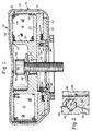
- a gyroscopic assembly 10 comprises a spool 12, an optical fiber coil 14 secured to and supported by the spool, an inner shield 16, and an outer or external shield 18.
- the spool includes a base 20 and a tubular wall 22 extending perpendicularly from the base to form an annularly shaped seat for supporting coil 14.
- Base 20 and wall 22 terminate in respective ends 24 and 26 to which a cover 28 is secured.
- Inner shield 16 is therefore defined by base 20, tubular wall 22 and cover 28.
- Outer shield 18 is formed from upper and lower shield portions 30 and 32, which are secured together at a joint 34.
- Spool 12 further includes a downwardly extending tubular wall 36 which forms, with base 20, an annularly shaped seat for supporting additional optical fibers and opto-electronic devices 37 therefor on or within an optics carrier 41, which latter elements are not germane to the present invention. Therefore, they will not be further discussed herein.
- a spacer ring 38 is secured to lower portion 32 of the outer shield, and includes an upwardly extending annular wall 40 which extends within downwardly extending annular wall 36 of the spool in a non-contacting, concentric manner.
- An optics carrier lid 42 is positioned to close off the annularly shaped seat defined by downwardly extending tubular wall 36 and base 20.
- Downwardly extending tubular wall 36 and upwardly extending annular wall 40 are provided with respective annularly configured grooves 44 and 46 into which an O-ring 48 resides to secure spool 12 and lower portion 32 together.
- Tubular wall 36 incorporates a tapered portion 45 that produces a centering function and facilitates the O-ring engagement into groove 44 while preventing any damage to the O-ring.
- O-ring 48 also serves to center the spool within outer shield 18, and avoids metal-to-metal contact therebetween.
- Groove 44 has a V-shaped configuration into which the O-ring can fit, while groove 46 has a U-shaped configuration to act as a retainer for the O-ring before and after assembly of the spool and outer shield.
- the grooves may be configured to have rounded edges to protect the O-ring from damage.
- Spool 12 and lower portion 32 of outer shield 18 are provided respectively with aligned central openings 50 and 52, through which a cap screw 54 extends.
- a head 56 on the cap screw sandwiches a Belleville washer 58, or lock washer, between it and spool 12.
- An opening 60 in upper portion 30 provides access to allow torquing of screw 54.
- the cap screw enables assembly 10 to be firmly secured to a support. After assembly 10 is firmly attached to the support by screw 54, the temporary interconnection between spool 12 and outer shield 18 is superseded thereby. Once the screw is tightened, a rigid attachment is achieved.
- Inner and outer shields 16 and 18 are formed of a highly permeable magnetic material, which is stress annealed to enhance and maximize the magnetic properties of assembly 10.
- the enhanced properties protect fiber optic coil 14 and its associated opto-electronic equipment from the effects of magnetic field interaction effects, such as Faraday rotation.
- the inner and outer shields act as paths to redirect possibly deleterious magnetic fields around the parts housed with the shields.
- the annealing process renders the shields generally malleable and, therefore, they are easily subject to harm. They are thus strain and impact sensitive and, should the assembly be harmed, such as by being dropped, bent, dented or even mishandled or slightly deformed, whether of an innocent or careless nature, the magnetic shielding properties will be compromised and, therefore, the magnetic properties invariably will be deleteriously affected.
- mishandling or mishap often occurs during the above-mentioned dismantling and disassembly, e.g., for repair and rework, when the inner shield and spool assembly must be separated from the outer shield.
- O-ring 46 in grooves 44 and 46 enables the assembly to be easily disassembled and re-assembled with little potential of harm.
Landscapes
- Physics & Mathematics (AREA)
- Engineering & Computer Science (AREA)
- Optics & Photonics (AREA)
- Electromagnetism (AREA)
- Power Engineering (AREA)
- General Physics & Mathematics (AREA)
- Radar, Positioning & Navigation (AREA)
- Remote Sensing (AREA)
- Gyroscopes (AREA)
Applications Claiming Priority (2)
| Application Number | Priority Date | Filing Date | Title |
|---|---|---|---|
| US09/302,705 US6259849B1 (en) | 1999-04-29 | 1999-04-29 | Rapid assembly and disassembly O-ring instrument mount for fiber optic gyroscopes |
| US302705 | 1999-04-29 |
Publications (2)
| Publication Number | Publication Date |
|---|---|
| EP1048930A2 true EP1048930A2 (de) | 2000-11-02 |
| EP1048930A3 EP1048930A3 (de) | 2001-12-12 |
Family
ID=23168878
Family Applications (1)
| Application Number | Title | Priority Date | Filing Date |
|---|---|---|---|
| EP00303550A Withdrawn EP1048930A3 (de) | 1999-04-29 | 2000-04-27 | Faseroptischer Kreisel |
Country Status (2)
| Country | Link |
|---|---|
| US (1) | US6259849B1 (de) |
| EP (1) | EP1048930A3 (de) |
Cited By (2)
| Publication number | Priority date | Publication date | Assignee | Title |
|---|---|---|---|---|
| CN102620728A (zh) * | 2012-03-22 | 2012-08-01 | 北京航空航天大学 | 一种用于高精度光纤陀螺的双层磁防护承环装置 |
| US8552725B2 (en) | 2009-12-07 | 2013-10-08 | Northrop Grumman Guidance & Electronics Company, Inc. | Systems and methods for obstructing magnetic flux while shielding a protected volume |
Families Citing this family (6)
| Publication number | Priority date | Publication date | Assignee | Title |
|---|---|---|---|---|
| US6462824B1 (en) * | 1999-12-15 | 2002-10-08 | Northrop Grumman Corporation | Snap fit magnetic shields for laser gyroscopes |
| US7121159B2 (en) * | 2002-03-01 | 2006-10-17 | Ganid Productions, Llc | Apparatus and method for gyroscopic propulsion |
| US6968112B2 (en) * | 2003-03-18 | 2005-11-22 | Northrop Grumman Corporation | Compact packaging of multiple fiber lasers |
| US7177028B2 (en) * | 2003-06-17 | 2007-02-13 | Litton Systems, Inc. | Reusable, high stiffness, magnetic shield for fiber optic gyroscopes |
| US9007598B1 (en) * | 2013-11-14 | 2015-04-14 | Honeywell International Inc. | Minimally-threaded screw to reduce alignment shifts |
| US10919773B2 (en) * | 2016-11-10 | 2021-02-16 | Umicore Ag & Co. Kg | Method for the preparation of a molecular sieve belonging to the ABC-6 framework family with disorder in the ABC stacking sequence |
Family Cites Families (6)
| Publication number | Priority date | Publication date | Assignee | Title |
|---|---|---|---|---|
| US5168756A (en) * | 1991-02-08 | 1992-12-08 | Sundstrand Corporation | Dithering coriolis rate and acceleration sensor utilizing a permanent magnet |
| EP0641996A1 (de) * | 1993-09-03 | 1995-03-08 | Litton Systems, Inc. | Aufnehmerspule eines Lichtleitfaserkreisels |
| US5545842A (en) * | 1993-10-26 | 1996-08-13 | Bal Seal Engineering Company, Inc. | Radially mounted spring to connect, lock and unlock, and for snap-on fastening, and for mechanical, electromagnetic shielding, electrical conductivity, and thermal dissipation with environmental sealing |
| US5486922A (en) * | 1994-12-20 | 1996-01-23 | Litton Systems, Inc. | Sensor coil with thermomechanically-matched spool for fiber optic gyroscope |
| NL1002898C2 (nl) * | 1996-04-18 | 1997-10-21 | Cordis Europ | Katheter met markeerhuls. |
| US5896199A (en) * | 1996-07-26 | 1999-04-20 | Litton Systems, Inc. | High efficiency magnetic shield for a fiber optic gyroscope |
-
1999
- 1999-04-29 US US09/302,705 patent/US6259849B1/en not_active Expired - Lifetime
-
2000
- 2000-04-27 EP EP00303550A patent/EP1048930A3/de not_active Withdrawn
Cited By (3)
| Publication number | Priority date | Publication date | Assignee | Title |
|---|---|---|---|---|
| US8552725B2 (en) | 2009-12-07 | 2013-10-08 | Northrop Grumman Guidance & Electronics Company, Inc. | Systems and methods for obstructing magnetic flux while shielding a protected volume |
| CN102620728A (zh) * | 2012-03-22 | 2012-08-01 | 北京航空航天大学 | 一种用于高精度光纤陀螺的双层磁防护承环装置 |
| CN102620728B (zh) * | 2012-03-22 | 2014-10-01 | 北京航空航天大学 | 一种用于高精度光纤陀螺的双层磁防护承环装置 |
Also Published As
| Publication number | Publication date |
|---|---|
| US6259849B1 (en) | 2001-07-10 |
| EP1048930A3 (de) | 2001-12-12 |
Similar Documents
| Publication | Publication Date | Title |
|---|---|---|
| US5896199A (en) | High efficiency magnetic shield for a fiber optic gyroscope | |
| US8083419B2 (en) | Optical module with an optical device electrically isolated from a sleeve shell | |
| US6259849B1 (en) | Rapid assembly and disassembly O-ring instrument mount for fiber optic gyroscopes | |
| EP0221180B1 (de) | Hermetische faserdichtung | |
| US10690872B2 (en) | Optical fiber protection structure and optical combiner structure using the same | |
| US6462824B1 (en) | Snap fit magnetic shields for laser gyroscopes | |
| JPH03501171A (ja) | 堅固化構造を有する光ファイバ貫通アセンブリ | |
| JPH0394205A (ja) | 光ファイバ取り付け装置 | |
| JPH09325299A (ja) | 光アイソレータ付き光ファイバ端子及びこれを用いた半導体レーザモジュール | |
| US10605994B2 (en) | Optical connector | |
| JP4049026B2 (ja) | 光結合部材、光モジュール及びその製造方法 | |
| US20050238295A1 (en) | Optical assembly with a sleeve assembly comprising a resin cover and a metal holder easily fitted thereto | |
| JPH0526746A (ja) | トルクセンサ用シールドの製造方法 | |
| JPH05501622A (ja) | 光接続装置及びビデオ信号伝送におけるその使用 | |
| JP2008268847A (ja) | 光アイソレータおよびそれを用いた光モジュール | |
| EP1298471A1 (de) | Vorrichtung zur Kopplung optischer Elemente in einem optischen Modul | |
| JPH10188757A (ja) | 温度ヒューズ | |
| US20030099274A1 (en) | Laser module | |
| JP2019179067A (ja) | 光モジュール | |
| JPS62248280A (ja) | レ−ザダイオ−ドモジユ−ルの光フアイバ固定構造 | |
| JPH04359208A (ja) | 受発光素子の固定構造 | |
| JPH10123375A (ja) | 光モジュール用パッケージ | |
| JPH11223748A (ja) | 光半導体素子モジュール及び、偏波消光比の確認方法 | |
| JPH0862453A (ja) | 光結合器 | |
| JP2002365446A (ja) | 光ファイバ導入部の封止構造 |
Legal Events
| Date | Code | Title | Description |
|---|---|---|---|
| PUAI | Public reference made under article 153(3) epc to a published international application that has entered the european phase |
Free format text: ORIGINAL CODE: 0009012 |
|
| AK | Designated contracting states |
Kind code of ref document: A2 Designated state(s): AT BE CH CY DE DK ES FI FR GB GR IE IT LI LU MC NL PT SE Kind code of ref document: A2 Designated state(s): DE FR GB IT |
|
| AX | Request for extension of the european patent |
Free format text: AL;LT;LV;MK;RO;SI |
|
| PUAL | Search report despatched |
Free format text: ORIGINAL CODE: 0009013 |
|
| AK | Designated contracting states |
Kind code of ref document: A3 Designated state(s): AT BE CH CY DE DK ES FI FR GB GR IE IT LI LU MC NL PT SE |
|
| AX | Request for extension of the european patent |
Free format text: AL;LT;LV;MK;RO;SI |
|
| 17P | Request for examination filed |
Effective date: 20020403 |
|
| AKX | Designation fees paid |
Free format text: DE FR GB IT |
|
| STAA | Information on the status of an ep patent application or granted ep patent |
Free format text: STATUS: THE APPLICATION IS DEEMED TO BE WITHDRAWN |
|
| 18D | Application deemed to be withdrawn |
Effective date: 20091031 |