EP0641996A1 - Aufnehmerspule eines Lichtleitfaserkreisels - Google Patents
Aufnehmerspule eines Lichtleitfaserkreisels Download PDFInfo
- Publication number
- EP0641996A1 EP0641996A1 EP94302000A EP94302000A EP0641996A1 EP 0641996 A1 EP0641996 A1 EP 0641996A1 EP 94302000 A EP94302000 A EP 94302000A EP 94302000 A EP94302000 A EP 94302000A EP 0641996 A1 EP0641996 A1 EP 0641996A1
- Authority
- EP
- European Patent Office
- Prior art keywords
- coil
- mounting member
- rotation sensor
- sensor according
- pedestal
- Prior art date
- Legal status (The legal status is an assumption and is not a legal conclusion. Google has not performed a legal analysis and makes no representation as to the accuracy of the status listed.)
- Withdrawn
Links
- 239000000835 fiber Substances 0.000 title claims abstract description 39
- NJPPVKZQTLUDBO-UHFFFAOYSA-N novaluron Chemical compound C1=C(Cl)C(OC(F)(F)C(OC(F)(F)F)F)=CC=C1NC(=O)NC(=O)C1=C(F)C=CC=C1F NJPPVKZQTLUDBO-UHFFFAOYSA-N 0.000 claims abstract description 25
- 239000000463 material Substances 0.000 claims abstract description 24
- 239000013307 optical fiber Substances 0.000 claims abstract description 15
- 239000010935 stainless steel Substances 0.000 claims abstract description 7
- 229910001220 stainless steel Inorganic materials 0.000 claims abstract description 7
- 239000000203 mixture Substances 0.000 claims abstract description 6
- RTAQQCXQSZGOHL-UHFFFAOYSA-N Titanium Chemical compound [Ti] RTAQQCXQSZGOHL-UHFFFAOYSA-N 0.000 claims abstract description 3
- 239000010936 titanium Substances 0.000 claims abstract description 3
- 229910052719 titanium Inorganic materials 0.000 claims abstract description 3
- 238000004382 potting Methods 0.000 claims description 15
- 230000007704 transition Effects 0.000 claims description 7
- 230000002093 peripheral effect Effects 0.000 claims description 4
- 238000004804 winding Methods 0.000 description 24
- 230000000694 effects Effects 0.000 description 12
- 230000007613 environmental effect Effects 0.000 description 11
- 239000010410 layer Substances 0.000 description 10
- 230000035945 sensitivity Effects 0.000 description 10
- 239000000853 adhesive Substances 0.000 description 6
- 230000001070 adhesive effect Effects 0.000 description 6
- 238000000034 method Methods 0.000 description 5
- 230000035882 stress Effects 0.000 description 5
- 238000005336 cracking Methods 0.000 description 4
- 239000011159 matrix material Substances 0.000 description 4
- 230000010363 phase shift Effects 0.000 description 4
- OKTJSMMVPCPJKN-UHFFFAOYSA-N Carbon Chemical compound [C] OKTJSMMVPCPJKN-UHFFFAOYSA-N 0.000 description 3
- 229910052799 carbon Inorganic materials 0.000 description 3
- 239000002131 composite material Substances 0.000 description 3
- 230000006835 compression Effects 0.000 description 3
- 238000007906 compression Methods 0.000 description 3
- 230000008569 process Effects 0.000 description 3
- 230000008901 benefit Effects 0.000 description 2
- 230000008859 change Effects 0.000 description 2
- 230000001419 dependent effect Effects 0.000 description 2
- 230000003287 optical effect Effects 0.000 description 2
- 230000006903 response to temperature Effects 0.000 description 2
- 229910001069 Ti alloy Inorganic materials 0.000 description 1
- 239000012790 adhesive layer Substances 0.000 description 1
- 229910052782 aluminium Inorganic materials 0.000 description 1
- XAGFODPZIPBFFR-UHFFFAOYSA-N aluminium Chemical compound [Al] XAGFODPZIPBFFR-UHFFFAOYSA-N 0.000 description 1
- 230000004323 axial length Effects 0.000 description 1
- 230000009286 beneficial effect Effects 0.000 description 1
- 230000015556 catabolic process Effects 0.000 description 1
- 238000006243 chemical reaction Methods 0.000 description 1
- 230000008878 coupling Effects 0.000 description 1
- 238000010168 coupling process Methods 0.000 description 1
- 238000005859 coupling reaction Methods 0.000 description 1
- 230000007423 decrease Effects 0.000 description 1
- 238000006731 degradation reaction Methods 0.000 description 1
- 230000032798 delamination Effects 0.000 description 1
- 230000002708 enhancing effect Effects 0.000 description 1
- 230000002452 interceptive effect Effects 0.000 description 1
- 238000004519 manufacturing process Methods 0.000 description 1
- 229910000595 mu-metal Inorganic materials 0.000 description 1
- 238000005457 optimization Methods 0.000 description 1
- 230000001151 other effect Effects 0.000 description 1
- 238000005295 random walk Methods 0.000 description 1
- 230000009467 reduction Effects 0.000 description 1
- 230000004044 response Effects 0.000 description 1
- 238000000926 separation method Methods 0.000 description 1
- 230000003595 spectral effect Effects 0.000 description 1
- 230000001629 suppression Effects 0.000 description 1
- 230000002277 temperature effect Effects 0.000 description 1
- 230000008646 thermal stress Effects 0.000 description 1
Images


Classifications
-
- G—PHYSICS
- G01—MEASURING; TESTING
- G01C—MEASURING DISTANCES, LEVELS OR BEARINGS; SURVEYING; NAVIGATION; GYROSCOPIC INSTRUMENTS; PHOTOGRAMMETRY OR VIDEOGRAMMETRY
- G01C19/00—Gyroscopes; Turn-sensitive devices using vibrating masses; Turn-sensitive devices without moving masses; Measuring angular rate using gyroscopic effects
- G01C19/58—Turn-sensitive devices without moving masses
- G01C19/64—Gyrometers using the Sagnac effect, i.e. rotation-induced shifts between counter-rotating electromagnetic beams
- G01C19/72—Gyrometers using the Sagnac effect, i.e. rotation-induced shifts between counter-rotating electromagnetic beams with counter-rotating light beams in a passive ring, e.g. fibre laser gyrometers
- G01C19/721—Details
- G01C19/722—Details of the mechanical construction
-
- G—PHYSICS
- G02—OPTICS
- G02B—OPTICAL ELEMENTS, SYSTEMS OR APPARATUS
- G02B6/00—Light guides; Structural details of arrangements comprising light guides and other optical elements, e.g. couplings
- G02B6/44—Mechanical structures for providing tensile strength and external protection for fibres, e.g. optical transmission cables
- G02B6/4439—Auxiliary devices
- G02B6/4457—Bobbins; Reels
Definitions
- the present invention relates to sensor coils for fiber optic gyroscopes.
- a fiber optic gyroscope normally comprises the following main components: (1) a light source, (2) a beamsplitter (either a fiber optic directional coupler or an integrated-optics Y-junction), (3) a fiber optic coil, (4) a polarizer (and sometimes one or more depolarizers), and (5) a detector.
- a light source is split by the beamsplitter into copropagating and counterpropagating waves that travel through the sensing coil.
- Associated electronics measures the phase relationships between the two interfering, counterpropagating, beams of light that emerge from the opposite ends of the coil. The difference between the phase shifts experienced by the two beams provides a measure of the rate of rotation of the platform to which the instrument is fixed.
- Environmental factors can affect the measured phase shift difference between the counterpropagating beams, thereby introducing a bias or error.
- Such environmental factors include variables such as temperature, vibration (acoustical and mechanical) and magnetic fields. These are both time-varying and unevenly distributed throughout the coil and induce variations in index of refraction and length that each counterpropagating wave encounters as it travels through the coil. The phase shifts imposed upon the two waves are unequal, producing a net undesirable phase shift which is indistinguishable from the rotation-induced signal.
- Pending patent application 08/017,678 of Huang et al. entitled “Apparatus For Reducing Magnetic Field-Induced Bias Errors in a Fiber Optic Gyroscope” addresses the suppression of bias errors induced by the Faraday effect in a sensor coil exposed to a magnetic field.
- the invention disclosed in that application (property of the assignee herein) teaches the use and design of compensator loops for counteracting the effects of both radially and axially-directed magnetic fields. In either case, a predetermined degree of twist of a preselected fiber twist mode is imposed upon the compensator loop to create a counteracting-corrective Faraday effect.
- the application discloses that the close matching of the thermal expansion characteristics of the spool and the fiber windings as well as proper selection of the coil potting material will minimize the Shupe-like bias caused by thermal stress that would be otherwise exerted by a standard metallic spool.
- careful selection of the potting material results in reduction of vibration-induced bias, coil cracking, degradation of h-parameter and temperature-ramp bias sensitivity.
- the present invention addresses sources of error associated with the mounting of a sensor coil by providing a rotation sensor for a fiber optic gyroscope that includes a substantially planar mounting member, a continuous optical fiber being arranged into a coil comprising a plurality of layers of coaxial turns and the turns of the coil being embedded in potting material of preselected composition; means are provided for fixing the coil to the member so that the axis of the coil is substantially orthogonal to the mounting member.
- a first portion of the coil is fixed to a first planar surface of the substantially planar mounting member and a second portion is fixed to the opposed surface.
- the flange may include means for guiding the continuous optical fiber between the first and second portions of the coil, such means including at least one arcuate groove located at the peripheral edge of the mounting flange.
- the substantially-planar mounting flange may be of titanium and may include (i) an annular, substantially-planar disk, (ii) a hub located at the center of the annular disk, and (iii) portions of the hub extend axially above and below the surface of the disk.
- the hub further may include (i) a cylindrical wall, (ii) the cylindrical wall comprising axial portions of first and second thicknesses, the region adjacent the first end of the wall being of the first thickness and the region adjacent the second, opposed end of the wall being of the second thickness and (iii) that the wall undergoes a transition from the first thickness to the second thickness over an intermediate axial region adjacent the junction of the wall to the disk.
- Means may be provided for maintaining a predetermined alignment of the axis of the coil.
- Such means may include (i) a stainless steel pedestal, (ii) means for aligning the pedestal with the predetermined axis, (iii) means for maintaining a predetermined orientation of the mounting flange with respect to the coil, (iv) a substantially-planar retainer element for securing the second end of the hub, and (v) means for fixing the retainer to the pedestal.
- the pedestal may include a shoulder.
- the second thickness of the cylindrical wall of the hub may exceed the first thickness and the shoulder may abut the first end of the hub.
- Figure 1 is a perspective view of a sensor coil 10 for a fiber optic gyroscope.
- the coil 10 is mounted upon a spool 12 of conventional design and provides a critical element of a fiber optic gyro system. In use, it is rigidly fixed to a platform whose rotation is to be measured, requiring means (not shown) for aligning the sensitive axis thereof with respect to the platform.
- Figure 2 is a fragmentary view in cross-section of a portion of the coil 10-and-spool 12 arrangement taken at line 2-2 of Fig. 1.
- the spool 12 comprises a central, generally-cylindrical,mandrel 14 that terminates in a pair of end flanges 16 and 18.
- the sensor coil 10 comprises a single continuous optical fiber 20 wound in a predetermined pattern upon the mandrel 14.
- a disk-like support 22 may be press-fit within the mandrel 14 and can include a central aperture 24 for receiving a fastener that secures the coil to the platform in a preferred alignment.
- the spool 10 may be of metallic composition or, alternatively, of a carbon composite composition as taught by pending United States patent application 07/797,198 for reducing the absolute differential in thermal expansion coefficients between the optical fiber 20 and the spool 12. In this way, temperature-induced Shupe effect stresses are minimized to a first order.
- the fiber 20 may be embedded or potted within a matrix of adhesive material 26.
- the matrix of potting material permits the designer to affect certain performance characteristics. In particular, through careful selection of the potting adhesive, sensitivity to vibration-induced bias errors is reduced.
- Figure 3 is a perspective view of a sensor coil 28, generally as described above, in combination with a mounting flange 30 in accordance with one embodiment of the invention.
- the arrangement of Figure 3 discloses a basic configuration in which a free-standing coil 28 is bonded by means of a conventional adhesive layer 32 to a disk-like planar member 31 of the mounting flange 30.
- the coil 28 is first fabricated by winding a continuous fiber 34 in a predetermined configuration upon a winding spool. During the winding process or thereafter the coil 28 is preferably impregnated with a potting material. After the potting material has cured, the wound coil 28 may then be removed from a winding spool to obtain the free standing configuration.
- FIG 4 is a perspective view of an alternative embodiment of the invention in which a mounting flange 36 includes a disk-like member 37 for accommodating a sensor coil 38 arranged into a back part 40 and a front part 42, (the two parts need not be 50-50) being mounted to opposed surfaces of the disk-like member 37. While the embodiment of Figure 4 will be disclosed and discussed in greater detail below, a central conceptual advantage of such configuration relates to the free-standing nature of the potted sensor coil 38.
- the power spectral density of environmental vibrations is a maximum in the region of 1100 Hz and decreases thereafter. It has been found that a 1 km sensor coil wound in an orthocyclic pattern and potted in a conventional adhesive material possesses a natural frequency that approximates 1100 Hz. By splitting the coil, one increases the resonant frequency of each half to beyond 2,000 Hz where environmental disturbances are minimal. For many applications, dependent upon the resultant coil geometry, it is thus highly advantageous to split the length of the cantilevered sensor coil, a result obtained by the arrangement of Figure 4.
- Figures 5(a) and 5(b) are bottom and side elevation views respectively of a mounting flange for supporting the split coil configuration illustrated in the preceding figure.
- the flange 44 generally comprises a disk-like planar member 46 joined to a central hub member 48 that extends therethrough.
- the inner wall thickness of the hub 48 varies along the axial length of the hub member 48. This reflects the coupling of the hub 48 to a pedestal (not showing in Figures 5(a) and 5(b)).
- the mounting flange preferably fabricated of a titanium alloy whose coefficient of thermal expansion closely matches the radial coefficient of thermal expansion of the potted coil, accepts the stainless steel mounting pedestal with the thinner portion thereof abutting the pedestal.
- the thinned portion of the wall of the hub 48 affords greater flexibility for preserving the alignment of the coil with a preselected input axis of rotation in the presence of otherwise-unbalancing radial expansion of the pedestal.
- Slots 49, 51 and communicating arcuate grooves 50 and 52 are provided at the periphery of the disk-shaped member 46 for permitting a gradual transition of the fiber between the front and back sections of the sensor coil.
- the grooves 50 and 52 are provided in the surface of the member 46 upon which the second half of the split coil is wound providing guides for guiding the fiber to the center of member 46.
- the split coil may be fabricated or wound upon the mounting flange 44 by first providing a take-up spool that is coaxial with and of greater diameter than the outside diameter of the hub 48.
- a quadrupole winding pattern is employed. After one half of the split coil has been wound upon beginning one side of the disk-like member 48, one then proceeds to the other side to wind the other half of the split coil.
- the split coil could be wound inwardly from the outer periphery of the disk-shaped member 46.
- the edge slots 49, 51 and the arcuate grooves 50, 52 are located, dimensioned and designed so that the fiber "transition " (i.e. the process of exiting the last turn of the winding pattern at one side of the disk 46 until beginning the first turn of the winding pattern at the opposed side) is gradual to minimize the introduction of microbends into the coil that can produce optical bias effects.
- the transition arrangements permit the transition of the fiber to take place over 3/4 of a fiber turn from the end of winding of one half of the split coil to the begining of winding of the other half of the coil.
- microbends can still be significantly reduced with an arrangement that obtains a transition from one side of the disk-like member 46 to the other over at least 1/4 fiber turn.
- Figure 6 is a side elevation view in cross-section of a split coil-and-mounting flange arrangement in accordance with Figs 4 & 5 and engaged to a pedestal 58 for operation.
- the device is contained within a ⁇ -metal shield 54 that interlocks with a base plate 56.
- the pedestal 58 preferably formed of stainless steel, receives an elongated member 60 that forms a portion of an inertial navigation system (INS).
- INS inertial navigation system
- the elongated member 60 is aligned with a predetermined axis that is intended to serve as the input axis of the sensor coil 62.
- INS inertial navigation system
- the sensor coil 62 is divided into a front half 64 and a back half 66, each comprising a plurality of turns of a continuous optical fiber.
- the coil 62 is mounted upon the disk-like member 68 of the mounting flange as illustrated in prior Figures 3 through 5.
- the wall thickness of front half 70 of the central hub of the mounting flange, which abuts and is supported by an encircling shoulder 71 of the stainless steel pedestal 58, is thinner than that of the back half which does not abut the pedestal.
- the thinner wall thickness of the front half of the hub provides added flexibility in the region of abutting pedestal and mounting flange materials of differing coefficients of thermal expansion.
- the angle of inclination of the disk-like portion 68 of the mounting flange is protected from misalignment when the device is subject to "excessive" thermally-induced radial expansion of the stainless steel pedestal to abut the front half wall of the hub.
- the attitude of the disk-like member 68 can remain perpendicular to the sensitive axis defined by the elongated member 60 over the expected temperature range and the sensor coil 62 will therefore remain properly aligned.
- a retainer plate 74 sits atop the back or "thick" half of the mounting flange hub. The entire assembly is, in turn, secured by means of a bolt 80 that completes the "sandwich” arrangement including the retainer plate 74, the pedestal 58 and the base plate 56.
- the division of the sensor coil into two relatively-separate parts permits opportunities for device optimization that are not present in a conventional coil design.
- Such possibilities follow from the potential advantages inherent in "mixed" coil designs. That is, the split coil configuration presents the designer with an opportunity to employ different winding techniques and patterns when creating the front and back halves of the sensor coil 62.
- the initial or starting winding points of the front and back halves may be displaced along the sensitive axis of the coil, either adjacent or removed from the disk-like member 68.
- the initial layer of the front or the back half may be displaced radially, either adjacent the peripheral edge of the disk-like member or in close proximity to the hub.
- corresponding layers of the front and back halves of the sensor coil i.e. vertically-aligned layers of each
- corresponding layers of the front and back halves may be wound in opposite directions.
- corresponding layers of the front and back halves may be wound in clockwise and counterclockwise directions.
- the split coil design permits the designer to consider minimization of the effects of environmental factors. Since the back half 66 of the split coil is so oriented as to be more exposed to environmental factors and since coil sensitivity is a function of distance from the winding center further minimization of environmental effects can be obtained by beginning the coil winding process with the back half.
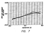
- Figure 7 is a graph that presents a measure of the stability of sensitive axis alignment as a function of temperature.
- a split coil arrangement in accordance with Figure 4 was employed for a 1 km sensor coil.
- the temperature of the mounting flange was cycled between -55 degrees C and 65 degrees C.
- An input axis alignment temperature coefficient of .02 arc-second/degree C was measured with a thermal fit residual of 0.38 arc-seconds. This performance fell well within the design specification of 0.3 arc-seconds/degree C (input axis alignment temperature coefficient) and 1.5 arc-seconds (thermal fit residual).
- the vibration performance of the 1 km split coil device was similarly satisfactory. By splitting the 1 km coil into two cantilevered halves, mechanical stressing due to environmental-range vibrations does not induce harmful resonances within the coil structure.
- Figures 8 (a) and 8 (b) are graphs of a temperature-time profile and the resulting bias error for the 1 km coil and mounting flange.
- Known Shupe error factors were readily modeled out of the data of Figure 8 (b), leaving the remaining temperature-dependent errors.
- the temperature at the mounting flange was cycled between -45 degrees C and 65 degrees C. After compensating for the Shupe temperature effect, a residual bias of less than .0092 degrees per hour was observed over a period of 21 hours. This clearly falls within the range of acceptable gyro performance.
- the present invention provides a sensor coil arrangement for a fiber optic gyroscope that can provide improved bias performance.
- a mounting flange, coil and pedestal as described, one can significantly reduce the bias error that is common to potted sensor coil arrangements mounted on conventional spools.
Landscapes
- Physics & Mathematics (AREA)
- Optics & Photonics (AREA)
- Engineering & Computer Science (AREA)
- General Physics & Mathematics (AREA)
- Electromagnetism (AREA)
- Power Engineering (AREA)
- Radar, Positioning & Navigation (AREA)
- Remote Sensing (AREA)
- Gyroscopes (AREA)
- Light Guides In General And Applications Therefor (AREA)
Applications Claiming Priority (2)
| Application Number | Priority Date | Filing Date | Title |
|---|---|---|---|
| US11637693A | 1993-09-03 | 1993-09-03 | |
| US116376 | 1993-09-03 |
Publications (1)
| Publication Number | Publication Date |
|---|---|
| EP0641996A1 true EP0641996A1 (de) | 1995-03-08 |
Family
ID=22366814
Family Applications (1)
| Application Number | Title | Priority Date | Filing Date |
|---|---|---|---|
| EP94302000A Withdrawn EP0641996A1 (de) | 1993-09-03 | 1994-03-21 | Aufnehmerspule eines Lichtleitfaserkreisels |
Country Status (5)
| Country | Link |
|---|---|
| US (1) | US5818590A (de) |
| EP (1) | EP0641996A1 (de) |
| JP (1) | JPH07103771A (de) |
| KR (1) | KR950009289A (de) |
| CA (1) | CA2117635A1 (de) |
Cited By (1)
| Publication number | Priority date | Publication date | Assignee | Title |
|---|---|---|---|---|
| CN108592901A (zh) * | 2018-04-27 | 2018-09-28 | 华中光电技术研究所(中国船舶重工集团有限公司第七七研究所) | 一种双柱型光纤环的绕环骨架 |
Families Citing this family (12)
| Publication number | Priority date | Publication date | Assignee | Title |
|---|---|---|---|---|
| US5778016A (en) | 1994-04-01 | 1998-07-07 | Imra America, Inc. | Scanning temporal ultrafast delay methods and apparatuses therefor |
| US6005665A (en) * | 1998-12-29 | 1999-12-21 | Honeywell, Inc. | Job zone for a high performance navigation grade rate sensing coil |
| US6320664B1 (en) * | 1998-12-31 | 2001-11-20 | Honeywell Inc. | Ruggedized structure for fiber optic gyroscope |
| US6259849B1 (en) * | 1999-04-29 | 2001-07-10 | Litton Systems, Inc. | Rapid assembly and disassembly O-ring instrument mount for fiber optic gyroscopes |
| US6486960B2 (en) * | 2001-02-27 | 2002-11-26 | Litton Systems, Inc. | Fiber optic sensor coil and tool for forming same |
| DE102005039152A1 (de) * | 2005-08-17 | 2007-02-22 | Robert Bosch Gmbh | Mechanische Trägereinrichtung sowie Messgerät mit einer mechanischen Trägereinrichtung |
| US7777889B2 (en) * | 2008-08-07 | 2010-08-17 | Honeywell International Inc. | Bias-instability reduction in fiber optic gyroscopes |
| US8281658B2 (en) | 2009-01-12 | 2012-10-09 | Taiwan Semiconductor Manufacturing Company, Ltd. | Method to produce 3-D optical gyroscope my MEMS technology |
| JP5651463B2 (ja) * | 2010-12-28 | 2015-01-14 | 東京計器株式会社 | 光ファイバジャイロ用センシングコイル及びその製造方法 |
| CN102607548B (zh) * | 2012-02-24 | 2014-12-31 | 北京航空航天大学 | 用于光纤陀螺的上下对称交叉绕制光纤环结构及绕制方法 |
| WO2013186852A1 (ja) * | 2012-06-12 | 2013-12-19 | 東京計器株式会社 | 光ファイバジャイロ用センシングコイル及びその製造方法 |
| CN104251710A (zh) * | 2013-06-28 | 2014-12-31 | 北京自动化控制设备研究所 | 一种抑制光纤陀螺温度漂移的传感环圈制备方法 |
Citations (5)
| Publication number | Priority date | Publication date | Assignee | Title |
|---|---|---|---|---|
| GB2146428A (en) * | 1983-09-10 | 1985-04-17 | Int Standard Electric Corp | Rotation rate measuring instrument |
| EP0292103A2 (de) * | 1987-03-27 | 1988-11-23 | Litton Systems Canada Limited | Faseroptische Messspule |
| EP0385682A2 (de) * | 1989-02-28 | 1990-09-05 | AT&T Corp. | Stabile Verpackung von langgezogenem Fasermaterial und Verfahren und Vorrichtung zu deren Erzeugung |
| EP0391557A2 (de) * | 1989-03-27 | 1990-10-10 | AT&T Corp. | Faseroptische Spule und Herstellungsverfahren |
| EP0429238A2 (de) * | 1989-11-13 | 1991-05-29 | Minnesota Mining And Manufacturing Company | Selbsttragender Lichtleitfaserwickel und Verfahren zu dessen Herstellung |
Family Cites Families (3)
| Publication number | Priority date | Publication date | Assignee | Title |
|---|---|---|---|---|
| US4856900A (en) * | 1987-06-03 | 1989-08-15 | Litton Systems, Inc. | Quadrupole-wound fiber optic sensing coil and method of manufacture thereof |
| US4883337A (en) * | 1988-08-29 | 1989-11-28 | The Charles Stark Draper Laboratory, Inc. | Low strain optical fiber coil |
| JPH04148823A (ja) * | 1990-10-11 | 1992-05-21 | Matsushita Electric Ind Co Ltd | 光ファイバジャイロ |
-
1994
- 1994-03-21 EP EP94302000A patent/EP0641996A1/de not_active Withdrawn
- 1994-05-12 KR KR1019940010347A patent/KR950009289A/ko not_active Application Discontinuation
- 1994-05-20 JP JP6106378A patent/JPH07103771A/ja not_active Withdrawn
- 1994-09-02 CA CA002117635A patent/CA2117635A1/en not_active Abandoned
-
1995
- 1995-09-11 US US08/526,725 patent/US5818590A/en not_active Expired - Lifetime
Patent Citations (5)
| Publication number | Priority date | Publication date | Assignee | Title |
|---|---|---|---|---|
| GB2146428A (en) * | 1983-09-10 | 1985-04-17 | Int Standard Electric Corp | Rotation rate measuring instrument |
| EP0292103A2 (de) * | 1987-03-27 | 1988-11-23 | Litton Systems Canada Limited | Faseroptische Messspule |
| EP0385682A2 (de) * | 1989-02-28 | 1990-09-05 | AT&T Corp. | Stabile Verpackung von langgezogenem Fasermaterial und Verfahren und Vorrichtung zu deren Erzeugung |
| EP0391557A2 (de) * | 1989-03-27 | 1990-10-10 | AT&T Corp. | Faseroptische Spule und Herstellungsverfahren |
| EP0429238A2 (de) * | 1989-11-13 | 1991-05-29 | Minnesota Mining And Manufacturing Company | Selbsttragender Lichtleitfaserwickel und Verfahren zu dessen Herstellung |
Cited By (1)
| Publication number | Priority date | Publication date | Assignee | Title |
|---|---|---|---|---|
| CN108592901A (zh) * | 2018-04-27 | 2018-09-28 | 华中光电技术研究所(中国船舶重工集团有限公司第七七研究所) | 一种双柱型光纤环的绕环骨架 |
Also Published As
| Publication number | Publication date |
|---|---|
| CA2117635A1 (en) | 1995-03-04 |
| US5818590A (en) | 1998-10-06 |
| KR950009289A (ko) | 1995-04-21 |
| JPH07103771A (ja) | 1995-04-18 |
Similar Documents
| Publication | Publication Date | Title |
|---|---|---|
| CA2157459C (en) | Slip interface for mounting gyro sensor coil | |
| EP0694761A1 (de) | Aufnehmerspule eines Lichtleitfaserkreisels | |
| EP0851213B1 (de) | Faseroptische Sensorspule mit Puffergebieten | |
| US5818590A (en) | Flange-supported sensor coil for a fiber optic gyroscope | |
| US5486922A (en) | Sensor coil with thermomechanically-matched spool for fiber optic gyroscope | |
| US5896199A (en) | High efficiency magnetic shield for a fiber optic gyroscope | |
| US5870194A (en) | Gyro sensor coil with filled optical fiber | |
| US6040908A (en) | Method for stress tuning fiber optic sensor coils | |
| EP0874219B1 (de) | Faseroptischer Kreisel | |
| EP1222440B1 (de) | Faseroptischer kreisel | |
| US5742390A (en) | Potted gyro sensor coil with inter-turn stress relief | |
| US5767970A (en) | Bonded fiber optic gyro sensor coil including voids | |
| EP0694760B1 (de) | Faserkreisel mit eingegossener Spule | |
| US6486960B2 (en) | Fiber optic sensor coil and tool for forming same | |
| JP3002095B2 (ja) | 低バイアス光ファイバジャイロスコープ用センサコイル | |
| EP3736533B1 (de) | Faseroptische gyroskop(fog)-anordnung | |
| CA2126034A1 (en) | Potted fiber optic gyro sensor coil for stringent vibration and thermal environments | |
| CA2117416A1 (en) | Sensor coil for low bias fiber optic gyroscope | |
| US20060268280A1 (en) | Method for winding sensing coils and sensing coil for fiber optic gyroscopes |
Legal Events
| Date | Code | Title | Description |
|---|---|---|---|
| PUAI | Public reference made under article 153(3) epc to a published international application that has entered the european phase |
Free format text: ORIGINAL CODE: 0009012 |
|
| AK | Designated contracting states |
Kind code of ref document: A1 Designated state(s): DE FR GB IT |
|
| 17P | Request for examination filed |
Effective date: 19950905 |
|
| 17Q | First examination report despatched |
Effective date: 19970306 |
|
| STAA | Information on the status of an ep patent application or granted ep patent |
Free format text: STATUS: THE APPLICATION IS DEEMED TO BE WITHDRAWN |
|
| 18D | Application deemed to be withdrawn |
Effective date: 19980109 |