EP1047212B1 - Gerät und Verfahren zum Übertragen von Audiodaten und Informationen bezüglich der Audiodaten - Google Patents
Gerät und Verfahren zum Übertragen von Audiodaten und Informationen bezüglich der Audiodaten Download PDFInfo
- Publication number
- EP1047212B1 EP1047212B1 EP00108036A EP00108036A EP1047212B1 EP 1047212 B1 EP1047212 B1 EP 1047212B1 EP 00108036 A EP00108036 A EP 00108036A EP 00108036 A EP00108036 A EP 00108036A EP 1047212 B1 EP1047212 B1 EP 1047212B1
- Authority
- EP
- European Patent Office
- Prior art keywords
- audio data
- audio
- related information
- sampling frequency
- sampling
- Prior art date
- Legal status (The legal status is an assumption and is not a legal conclusion. Google has not performed a legal analysis and makes no representation as to the accuracy of the status listed.)
- Expired - Lifetime
Links
- 238000012546 transfer Methods 0.000 title claims description 59
- 238000000034 method Methods 0.000 title claims description 13
- 238000005070 sampling Methods 0.000 claims description 87
- 238000006243 chemical reaction Methods 0.000 claims description 14
- 230000005540 biological transmission Effects 0.000 claims description 6
- 238000001514 detection method Methods 0.000 claims 1
- 238000012545 processing Methods 0.000 description 7
- 238000010586 diagram Methods 0.000 description 4
- 230000010365 information processing Effects 0.000 description 4
- 238000007796 conventional method Methods 0.000 description 2
- 238000012544 monitoring process Methods 0.000 description 2
- 230000000052 comparative effect Effects 0.000 description 1
- 230000003247 decreasing effect Effects 0.000 description 1
- 230000015654 memory Effects 0.000 description 1
- 239000013307 optical fiber Substances 0.000 description 1
- 230000000717 retained effect Effects 0.000 description 1
- 230000005236 sound signal Effects 0.000 description 1
- 230000009466 transformation Effects 0.000 description 1
Images


Classifications
-
- H—ELECTRICITY
- H04—ELECTRIC COMMUNICATION TECHNIQUE
- H04B—TRANSMISSION
- H04B14/00—Transmission systems not characterised by the medium used for transmission
- H04B14/02—Transmission systems not characterised by the medium used for transmission characterised by the use of pulse modulation
- H04B14/04—Transmission systems not characterised by the medium used for transmission characterised by the use of pulse modulation using pulse code modulation
-
- G—PHYSICS
- G10—MUSICAL INSTRUMENTS; ACOUSTICS
- G10L—SPEECH ANALYSIS TECHNIQUES OR SPEECH SYNTHESIS; SPEECH RECOGNITION; SPEECH OR VOICE PROCESSING TECHNIQUES; SPEECH OR AUDIO CODING OR DECODING
- G10L19/00—Speech or audio signals analysis-synthesis techniques for redundancy reduction, e.g. in vocoders; Coding or decoding of speech or audio signals, using source filter models or psychoacoustic analysis
-
- G—PHYSICS
- G11—INFORMATION STORAGE
- G11B—INFORMATION STORAGE BASED ON RELATIVE MOVEMENT BETWEEN RECORD CARRIER AND TRANSDUCER
- G11B20/00—Signal processing not specific to the method of recording or reproducing; Circuits therefor
- G11B20/10—Digital recording or reproducing
- G11B20/10527—Audio or video recording; Data buffering arrangements
-
- G—PHYSICS
- G11—INFORMATION STORAGE
- G11B—INFORMATION STORAGE BASED ON RELATIVE MOVEMENT BETWEEN RECORD CARRIER AND TRANSDUCER
- G11B20/00—Signal processing not specific to the method of recording or reproducing; Circuits therefor
- G11B20/00007—Time or data compression or expansion
- G11B2020/00014—Time or data compression or expansion the compressed signal being an audio signal
-
- G—PHYSICS
- G11—INFORMATION STORAGE
- G11B—INFORMATION STORAGE BASED ON RELATIVE MOVEMENT BETWEEN RECORD CARRIER AND TRANSDUCER
- G11B20/00—Signal processing not specific to the method of recording or reproducing; Circuits therefor
- G11B20/10—Digital recording or reproducing
- G11B20/10527—Audio or video recording; Data buffering arrangements
- G11B2020/10537—Audio or video recording
- G11B2020/10546—Audio or video recording specifically adapted for audio data
Definitions
- the present invention relates to a method and apparatus for digitally transferring audio data and audio-related information.
- audio data is distinguished from “audio-related information”.
- the “audio data” is the information representing the actual sounds to be reproduced.
- the “audio-related information” is defined as any information that does not directly represent the actual sounds to be reproduced, e.g., category codes, source numbers, and channel numbers.
- IEC60958 which is used for transferring 2-channel linear PCM data, is used in a wide range of digital data transfer applications including CDs and DVDs.
- IEC61937 is used for the transfer of data other than linear PCM data, such as compressed data (e.g., data compressed according to the MPEG standards) .
- compressed data e.g., data compressed according to the MPEG standards
- IEC61937 is used in applications where the multi-channel audio outputs from a DVD apparatus are utilized for reproduction by an external decoder amplifier connected to the DVD apparatus.
- the aforementioned conventional methods for transferring audio data and audio-related information aim at simply reproducing the transferred audio data.
- the aforementioned conventional transfer standards do not support sampling frequencies such as 96 kHz and 192 kHz. Therefore, when a player is connected to an external apparatus, the original audio data is subjected to a down sampling process or the like for converting the sampling frequency to 48 kHz before transfer. In this case, however, there is a problem in that the external apparatus receiving the transferred data is not aware of the value of the sampling frequency at which the original audio data was sampled.
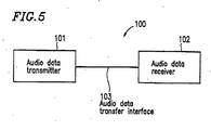
- FIG. 5 shows an audio data transfer apparatus 100 as a consumer-use digital audio apparatus .
- the audio data transfer apparatus 100 includes an audio data transmitter 101 for transmitting audio data and an audio data receiver 102 for receiving the transmitted audio data, the transmitter 101 and the receiver 102 being interconnected via an audio data transfer interface 103 designed for audio data, transfer.
- Tables 1 and 2 show transfer conditions for transferring audio data from the audio data transmitter 101 in the aforementioned audio data transfer apparatus 100.
- the transfer conditions for the audio data transfer apparatus 100 include up-sampling, down-sampling, sampling conversion, N times speed transfer, 1/N times speed transfer, etc., in addition to transferring the original audio data at the originally-intended speed.
- the sampling frequency of the transferred audio data differs from that of the original audio data.
- the audio-related information which is transferred in the conventional audio data transfer apparatus 100 does not include information concerning the sampling frequency of the original audio data.
- the audio data receiver 102 cannot obtain any information concerning the sampling frequency of the original audio data.
- Figure 6 illustrates an example of a conventional audio data/audio-related information recording format 300.
- the conventional audio data/audio-related information recording format 300 contains no information indicating the sampling frequency of the original audio data or no information indicating the transfer speed of the transferred audio data. Hence, it is impossible for the audio data receiver 102 to detect the sampling frequency of the original audio data or the transfer speed of the transferred audio data.
- US 5,577,044 relates to a serial data bus protocol for audio data transmission and reception and teaches that the protocol involves multiplexing the audio data and control/status data. The multiplexed data is then transferred between a first audio unit and a second audio unit on two wires each corresponding to the direction of data flow, and according to a clock and a synchronization pattern on third and fourth wires, respectively.
- US 5, 892,746 discloses a system for recording or reproducing PCM audio signals having different sampling frequencies, wherein the audio data is transformed into transformation coefficients in a frequency domain.
- a method for transferring audio data and audio-related information comprising: a generation step of generating second audio data from first audio data; a transmission step of transmitting the second audio data and audio-related information associated with the second audio data; and a reception step of receiving the second audio data and the audio-related information, wherein the audio-related information includes information representing a sampling frequency of the first audio data.
- the transmission step comprises a conversion step of converting the sampling frequency of the first audio data into a sampling frequency which is suitable for reproduction at the reception step.
- the conversion step comprises a down-sampling.
- the conversion step comprises an up-sampling.
- the conversion step comprises a sampling conversion.
- the reception step comprises displaying the sampling frequency of the first audio data on a display.
- an audio data/audio-related information transfer apparatus for transferring audio data and audio-related information, comprising: a transmission for transmitting second audio data and audio-related information associated with the second audio data, the second audio data being generated from first audio data; and a receiver for receiving the second audio data and the audio-related information, wherein the audio-related information includes information representing a sampling frequency of the first audio data.
- the transmitter converts the sampling frequency of the first audio data into a sampling frequency which is suitable for reproduction by the receiver.
- the transmitter performs a down-sampling for the sampling frequency of the first audio data.
- the transmitter performs an up-sampling for the sampling frequency of the first audio data.
- the' transmitter performs a sampling conversion for the sampling frequency of the first audio data.
- the receiver comprises a display for displaying the sampling frequency of the first audio data.
- a transmitter for transmitting second audio data and audio-related information associated with the second audio data, the second audio data being generated from first audio data, wherein the audio-related information includes information representing a sampling frequency of the first audio data.
- the transmitter converts the sampling frequency of the first audio data into a sampling frequency which is suitable for reproduction by the receiver.
- the transmitter performs a down-sampling for the sampling frequency of the first audio data.
- the transmitter performs an up-sampling for the sampling frequency of the first audio data.
- the transmitter performs a sampling conversion for the sampling frequency of the first audio data.
- a receiver for receiving second audio data and audio-related information associated with the second audio data, the second audio data being generated from first audio data and transmitted from a transmitter, wherein the audio-related information includes information representing a sampling frequency of the first audio data.
- the receiver comprises a display for displaying the sampling frequency of the first audio data.
- the invention described herein makes possible the advantage of providing a method and apparatus for performing digital transfer of audio data which involves concurrently transferring, information indicating a sampling frequency, thereby enabling a mode of audio reproduction which is in accordance with the particular audio data that is being transferred.
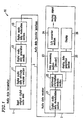
- FIG. 1 illustrates an audio data transfer apparatus 10 according to an example of the present invention.
- the audio data transfer apparatus 10 includes an audio data transmitter 1 for transmitting audio data and an audio data receiver 2 for receiving the transmitted audio data, the audio data transmitter 1 and the audio data receiver 2 being interconnected via an audio data transfer interface 3 designed for audio data transfer.
- the audio data transmitter 1 may be a DVD player or a set top box (STB), for example.
- the audio data receiver 2 may be an AV decoder or a minidisk apparatus, for example.
- the audio data transfer interface 3 may be a conductive cable or an optical fiber, for example.
- audio data is first analyzed by a digital audio data attribute analysis section 11. Then, a digital audio data generation section 12 adds appropriate audio-related information to the audio data (described below). Thereafter, the audio data is modulated by a digital audio data modulation section 13, and-output to the audio data transfer interface 3 so as to be transferred to the audio data receiver 2.
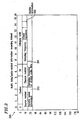
- Figure 2 illustrates an audio data/audio-related information recording format 200 according to an example of the present invention.
- sampling frequency data of the original audio data are assigned in a region 201 spanning the 36th to 39th bits.
- Table 3 shows the correspondence between the sampling frequency of the original audio data and bit information.
- sampling frequencies which are currently in common use (i.e., 32 kHz, 44.1 kHz, and 48 kHz); frequencies twice those values (i.e., 64 kHz, 88.2 kHz, and96 kHz); and frequencies half those values (i.e., 16 kHz, 22.05 kHz, and 24 kHz).
- the audio data/audio-related information recording format 200 ( Figure 2 ) includes information representing the sampling frequency of the original audio data as illustrated in Table 3, it is possible for the audio data receiver 2 to detect the sampling frequency of the original audio data even in the case where the audio data to be transferred are down-sampled from the sampling frequencies 96 kHz and 88.2 kHz, which are adopted by the DVD audio standards. Moreover, the audio data/audio-related information recording format 200 ( Figure 2 ) also supports half-rate frequencies of the MPEG2 frequencies, which are adopted by digital satellite broadcast. Even in the case where the audio data to be transferred are up-sampled from such frequencies, it is possible for the audio data receiver 2 to detect the audio-related information associated with the original audio data.
- monitor information is assigned in a region 202 at bit 30.
- the monitor information can be expressed by one bit as shown in Table 4.
- the audio data transmitter 1 sets bit 30 to "1'' if it is possible to monitor the audio data, and sets bit 30 to "0" if monitoring ability is not guaranteed (e.g., if it is impossible to monitor the audio data).
- transfer speed information is assigned in a region 203 spanning the 32nd to 35th bits.
- the transfer speed information may be expressed by four bits as shown in Table 5, for example.
- the audio data/audio-related information recording format 200 ( Figure 2 ) includes information representing the transfer speed information as illustrated in Table 5, it is possible for the audio data receiver 2 to detect the transfer speed of audio data even in the case where the audio data is transferred at an N times or 1/N times speed.
- the audio data receiver 2 includes a data processing means which is capable of reproducing audio data at varying speeds, it is possible to vary the reproduction speed of the received audio data on the basis of the detected transfer speed information.
- Table 5 illustrates 4 times to 1/4 times transfer speeds
- the present invention is applicable to any transfer speed.
- the audio data as well as audio-related information including the aforementioned additional information (e.g., sampling frequency information and transfer speed information), is transferred to the audio data receiver 2 in accordance with the audio data transfer apparatus 10 .
- additional information e.g., sampling frequency information and transfer speed information
- the received audio data and audio-related information is demodulated by a digital audio data demodulation section 21 , and the audio-related information is analyzed by an additional information analysis section 22 . Then, after the audio data is processed by a data processing section 23 , the audio data is converted into an analog signal by a D/A converter section 24 for output.
- a display data generation section 25 generates display data based on the audio-related information, which is displayed on a display 26.
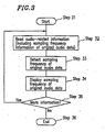
- Figure 3 is a flowchart showing a flow of steps for a processing of the sampling frequency information of original audio data which is performed by the audio data receiver 2 .
- audio-related information including the sampling frequency information of original audio data is read by an additional information analysis section 22 of the audio data receiver 2.
- the additional information analysis section 22 looks up in Table 3 the bit information representing the sampling frequency of the original audio data that has been read, thereby detecting the sampling frequency of the original audio data.
- the display data generation section 25 displays the detected sampling frequency of the original audio data on the display 26.
- Figure 4 is a flowchart showing the monitor information processing performed in the audio data receiver 2 . Specifically, Figure 4 illustrates monitor information processing performed in the case where the audio-related information does not include transfer speed information, or where the audio data receiver 2 does not include a data processing means which is capable of reproducing audio data at varying speeds.
- audio-related information including the monitor information of original audio data is read by the additional information analysis section 22 of the audio data receiver 2 .
- the additional information analysis section 22 detects or determines whether or not the monitor bit (e.g., bit 30) is "1". if the monitor bit is "1", it is possible to monitor the audio data, so that the transferred data is subjected to appropriate signal processing at the data processing section 23 and the D/A converter section 24 , and thereafter output as audio data at Step 44 .
- the display 26 displays information indicating that the audio data can be monitored or is being monitored.
- the audio data transmitter 1 transmits "0" as the monitor bit to indicate that the audio data cannot be monitored.
- the monitor information indicating that monitoring is impossible is read by the additional information analysis section 22 in the audio data receiver 2 , the audio output is muted at Step 45 , and the display 26 displays information indicating that the audio data cannot be monitored or is being muted at Step 49 .
- the transfer speed information is analyzed by the additional information analysis section 22, and the transfer speed is displayed on the display 26.
- the audio data receiver 2 includes a data processing means which is capable of reproducing audio data at varying speeds
- the speed of the audio data is changed based on the detected transfer speed information, and the audio data is reproduced at the changed speed.
- sampling frequency information, the monitor information, and the transfer speed information of the original audio data may all be included in the audio data/audio-related information recording format 200.
- each type of information may be selectively included depending on the needs of the particular application.
- the audio data/audio-related information recording format 200 may only include the sampling frequency information of the original audio data.
- the audio data/audio-related information recording format 200 described above is only illustrative. Any other format may be employed as the audio data/audio-related information recording format 200.
- audio data transfer is achieved via an audio data transfer interface 3
- audio data may be transferred by any other transfer means that is capable of transferring digital information.
- the present invention is applicable not only to the IEC 60958 and IEC61937 transfer standards but also any digital data transfer standards, e.g., IEEE 1394, which is a set of audio video data transfer standards to be enforced in future.
- any digital data transfer standards e.g., IEEE 1394, which is a set of audio video data transfer standards to be enforced in future.
- an audio data transmitter adds, to audio data to be transferred, information indicating a sampling frequency of the original audio data.
- various information concerning the transferred data can be detected by the audio data receiver. This enables a mode of audio reproduction which is in accordance with the particular audio data that is being transferred.
Landscapes
- Engineering & Computer Science (AREA)
- Signal Processing (AREA)
- Human Computer Interaction (AREA)
- Computational Linguistics (AREA)
- Health & Medical Sciences (AREA)
- Audiology, Speech & Language Pathology (AREA)
- Computer Networks & Wireless Communication (AREA)
- Physics & Mathematics (AREA)
- Acoustics & Sound (AREA)
- Multimedia (AREA)
- Signal Processing For Digital Recording And Reproducing (AREA)
- Communication Control (AREA)
- Stereophonic System (AREA)
Claims (12)
- Verfahren zum Übertragen von Audiodaten und von Informationen bezüglich der Audiodaten, das umfasst:dadurch gekennzeichnet, dass die Informationen bezüglich der Audiodaten Informationen enthalten, die eine Abtastfrequenz der ersten Audiodaten repräsentieren.einen Erzeugungsschritt zum Erzeugen zweiter Audiodaten aus ersten Audiodaten, der eine Abtastumsetzung umfasst;einen Übertragungsschritt zum Übertragen der zweiten Audiodaten und der den zweiten Audiodaten zugeordneten Informationen bezüglich der Audiodaten; undeinen Empfangsschritt zum Empfangen der zweiten Audiodaten und der Informationen bezüglich der Audiodaten,
- Verfahren nach Anspruch 1, bei dem die Abtastfrequenz der ersten Audiodaten in eine Abtastfrequenz umgesetzt wird, die für die Wiedergabe in dem Empfangsschritt geeignet ist.
- Verfahren nach Anspruch 2, bei dem die Abtastumsetzung eine Abwärtsabtastung umfasst.
- Verfahren nach Anspruch 2, bei dem die Abtastumsetzung eine Aufwärtsabtastung umfasst.
- Verfahren nach Anspruch 1, bei dem der Empfangsschritt das Anzeigen der Abtastfrequenz der ersten Audiodaten auf einer Anzeige umfasst.
- Sender, der Mittel zum Senden zweiter Audiodaten und den zweiten Audiodaten zugeordneter Informationen bezüglich der Audiodaten, sowie Mittel zum Erzeugen der zweiten Audiodaten aus ersten Audiodaten durch Abtastumsetzung umfasst, dadurch gekennzeichnet, dass die Informationen bezüglich der Audiodaten Informationen enthalten, die eine Abtastfrequenz der ersten Audiodaten repräsentieren.
- Sender nach Anspruch 6, wobei der Sender Mittel umfasst, um die Abtastfrequenz der ersten Audiodaten in eine Abtastfrequenz umzusetzen, die für die Wiedergabe durch einen Empfänger (2) geeignet ist.
- Sender nach Anspruch 7, wobei der Sender Mittel umfasst, um eine Abwärtsabtastung für die Abtastfrequenz der ersten Audiodaten auszuführen.
- Sender nach Anspruch 7, wobei der Sender Mittel umfasst, um eine Aufwärtsabtastung der Abtastfrequenz der ersten Audiodaten auszuführen.
- Empfänger, der Mittel zum Empfangen zweiter Audiodaten und Informationen bezüglich der Audiodaten, die den zweiten Audiodaten zugeordnet sind, umfasst, wobei die zweiten Audiodaten durch Abtastumsetzung aus ersten Audiodaten erzeugt und von einem Sender (1) gesendet werden,
dadurch gekennzeichnet, dass die audiorelevanten Informationen Informationen enthalten, die eine Abtastfrequenz der ersten Audiodaten repräsentieren,
und dass er Erfassungsmittel umfasst, um die Abtastfrequenz der ersten Audiodaten zu erfassen. - Empfänger nach Anspruch 10, wobei der Empfänger (2) eine Anzeige (26) zum Anzeigen der Abtastfrequenz der ersten Audiodaten umfasst.
- Vorrichtung zum Übertragen von Audiodaten/Informationen bezüglich der Audiodaten, um Audiodaten und Informationen bezüglich der Audiodaten zu übertragen, die umfasst:einen Sender (1) nach einem der Ansprüche 6 bis 9; undeinen Empfänger (2) nach einem der Ansprüche 10 oder 11.
Priority Applications (1)
| Application Number | Priority Date | Filing Date | Title |
|---|---|---|---|
| EP03029484A EP1404039B1 (de) | 1999-04-23 | 2000-04-20 | Gerät und Verfahren zum Übertragen von Audiodaten und Audiobezogenen Informationen |
Applications Claiming Priority (4)
| Application Number | Priority Date | Filing Date | Title |
|---|---|---|---|
| JP11588599 | 1999-04-23 | ||
| JP11588599 | 1999-04-23 | ||
| JP2000102883 | 2000-04-04 | ||
| JP2000102883A JP2001005499A (ja) | 1999-04-23 | 2000-04-04 | 音楽データ情報伝送方法および装置 |
Related Child Applications (1)
| Application Number | Title | Priority Date | Filing Date |
|---|---|---|---|
| EP03029484A Division EP1404039B1 (de) | 1999-04-23 | 2000-04-20 | Gerät und Verfahren zum Übertragen von Audiodaten und Audiobezogenen Informationen |
Publications (3)
| Publication Number | Publication Date |
|---|---|
| EP1047212A2 EP1047212A2 (de) | 2000-10-25 |
| EP1047212A3 EP1047212A3 (de) | 2001-11-14 |
| EP1047212B1 true EP1047212B1 (de) | 2004-06-02 |
Family
ID=26454305
Family Applications (2)
| Application Number | Title | Priority Date | Filing Date |
|---|---|---|---|
| EP03029484A Expired - Lifetime EP1404039B1 (de) | 1999-04-23 | 2000-04-20 | Gerät und Verfahren zum Übertragen von Audiodaten und Audiobezogenen Informationen |
| EP00108036A Expired - Lifetime EP1047212B1 (de) | 1999-04-23 | 2000-04-20 | Gerät und Verfahren zum Übertragen von Audiodaten und Informationen bezüglich der Audiodaten |
Family Applications Before (1)
| Application Number | Title | Priority Date | Filing Date |
|---|---|---|---|
| EP03029484A Expired - Lifetime EP1404039B1 (de) | 1999-04-23 | 2000-04-20 | Gerät und Verfahren zum Übertragen von Audiodaten und Audiobezogenen Informationen |
Country Status (6)
| Country | Link |
|---|---|
| US (2) | US6584443B1 (de) |
| EP (2) | EP1404039B1 (de) |
| JP (1) | JP2001005499A (de) |
| CN (1) | CN100356473C (de) |
| CA (1) | CA2306298C (de) |
| DE (2) | DE60011182T2 (de) |
Families Citing this family (10)
| Publication number | Priority date | Publication date | Assignee | Title |
|---|---|---|---|---|
| JP2001005499A (ja) * | 1999-04-23 | 2001-01-12 | Matsushita Electric Ind Co Ltd | 音楽データ情報伝送方法および装置 |
| EP1223696A3 (de) | 2001-01-12 | 2003-12-17 | Matsushita Electric Industrial Co., Ltd. | System zur Übertragung von digitalen Audiodaten nach dem MOST-Verfahren |
| US6804655B2 (en) * | 2001-02-06 | 2004-10-12 | Cirrus Logic, Inc. | Systems and methods for transmitting bursty-asnychronous data over a synchronous link |
| DE10291762B4 (de) * | 2001-04-25 | 2014-07-10 | Sony Corporation | Datenübertragungsverfahren und Datenübertragungsgerät zum Übertragen von Datenstromdaten |
| US7333934B1 (en) * | 2003-04-06 | 2008-02-19 | Apple Inc. | Pre-processing individual audio items in a media project in order to improve real-time processing of the media project |
| JP4353278B2 (ja) | 2007-05-30 | 2009-10-28 | ソニー株式会社 | デジタル記録装置及び方法、デジタル再生装置及び方法、並びにデジタルデータ変換装置 |
| US11074031B1 (en) | 2016-09-06 | 2021-07-27 | Colin Leonard | Systems and methods for dynamic audio processing |
| US10546610B2 (en) * | 2011-08-13 | 2020-01-28 | Colin Leonard | Systems and methods for dynamic audio processing |
| CN113012722B (zh) | 2019-12-19 | 2022-06-10 | 腾讯科技(深圳)有限公司 | 采样率处理方法、装置、系统、存储介质和计算机设备 |
| CN116781180B (zh) * | 2023-06-05 | 2023-11-10 | 广州市高科通信技术股份有限公司 | 一种pcm通道扩容方法及扩容系统 |
Family Cites Families (20)
| Publication number | Priority date | Publication date | Assignee | Title |
|---|---|---|---|---|
| US44309A (en) * | 1864-09-20 | Improvement in the manufacture of wash-boilers and other vessels | ||
| US4553129A (en) | 1983-08-05 | 1985-11-12 | Gte Communication Systems Corporation | Data transmission by subrate grouping |
| JPS63253568A (ja) * | 1987-04-09 | 1988-10-20 | Victor Co Of Japan Ltd | デジタル信号記録再生装置 |
| US5228059A (en) | 1989-11-21 | 1993-07-13 | Nippon Hoso Kyokai | Differential code transmission system |
| US5689534A (en) | 1992-05-12 | 1997-11-18 | Apple Computer, Inc. | Audio functional unit and system and method for configuring the same |
| CN1084306A (zh) | 1992-09-17 | 1994-03-23 | 鲍炜 | 自由录放方法及系统 |
| JP3197766B2 (ja) * | 1994-02-17 | 2001-08-13 | 三洋電機株式会社 | Mpegオーディオデコーダ、mpegビデオデコーダおよびmpegシステムデコーダ |
| JP3591011B2 (ja) * | 1994-11-04 | 2004-11-17 | ソニー株式会社 | ディジタル信号処理装置 |
| JPH09232962A (ja) * | 1996-02-27 | 1997-09-05 | Sony Corp | 信号伝送方法及び装置 |
| US5777997A (en) * | 1996-03-07 | 1998-07-07 | Hughes Electronics Corporation | Method and system for transmitting audio-associated text information in a multiplexed transmission stream |
| US5892746A (en) * | 1996-06-15 | 1999-04-06 | Samsung Electronics Co., Ltd. | System for recording and/or reproducing a pulse code modulation digital audio signal |
| JP3131564B2 (ja) * | 1996-07-03 | 2001-02-05 | 松下電器産業株式会社 | 放送システム、サービス提供装置及び受信端末装置 |
| US6049272A (en) * | 1997-01-22 | 2000-04-11 | Boyd B. Moore et al. | Automated data transmission link to law enforcement and security personnel |
| US6175592B1 (en) * | 1997-03-12 | 2001-01-16 | Matsushita Electric Industrial Co., Ltd. | Frequency domain filtering for down conversion of a DCT encoded picture |
| CN1098518C (zh) | 1997-07-11 | 2003-01-08 | 三星电子株式会社 | 与数字通用盘视频标准兼容的数字音频处理系统 |
| JP3994360B2 (ja) | 1998-05-20 | 2007-10-17 | ソニー株式会社 | 情報処理装置、情報処理方法、および記録媒体 |
| JP2000259195A (ja) * | 1999-01-08 | 2000-09-22 | Matsushita Electric Ind Co Ltd | デコード回路及びそれを用いた再生装置 |
| JP2000278136A (ja) * | 1999-03-19 | 2000-10-06 | Mitsubishi Electric Corp | 復号装置 |
| JP2001005499A (ja) * | 1999-04-23 | 2001-01-12 | Matsushita Electric Ind Co Ltd | 音楽データ情報伝送方法および装置 |
| US6673995B2 (en) * | 2000-11-06 | 2004-01-06 | Matsushita Electric Industrial Co., Ltd. | Musical signal processing apparatus |
-
2000
- 2000-04-04 JP JP2000102883A patent/JP2001005499A/ja active Pending
- 2000-04-20 EP EP03029484A patent/EP1404039B1/de not_active Expired - Lifetime
- 2000-04-20 DE DE60011182T patent/DE60011182T2/de not_active Expired - Lifetime
- 2000-04-20 DE DE60042346T patent/DE60042346D1/de not_active Expired - Lifetime
- 2000-04-20 US US09/553,590 patent/US6584443B1/en not_active Expired - Lifetime
- 2000-04-20 EP EP00108036A patent/EP1047212B1/de not_active Expired - Lifetime
- 2000-04-20 CA CA002306298A patent/CA2306298C/en not_active Expired - Lifetime
- 2000-04-24 CN CNB001062484A patent/CN100356473C/zh not_active Expired - Lifetime
-
2003
- 2003-04-28 US US10/249,650 patent/US7069224B2/en not_active Expired - Lifetime
Also Published As
| Publication number | Publication date |
|---|---|
| US6584443B1 (en) | 2003-06-24 |
| EP1404039B1 (de) | 2009-06-03 |
| DE60011182T2 (de) | 2004-10-07 |
| DE60042346D1 (de) | 2009-07-16 |
| EP1047212A3 (de) | 2001-11-14 |
| CA2306298A1 (en) | 2000-10-23 |
| CA2306298C (en) | 2005-07-05 |
| DE60011182D1 (de) | 2004-07-08 |
| US7069224B2 (en) | 2006-06-27 |
| CN100356473C (zh) | 2007-12-19 |
| EP1404039A3 (de) | 2004-04-07 |
| EP1404039A2 (de) | 2004-03-31 |
| JP2001005499A (ja) | 2001-01-12 |
| CN1271936A (zh) | 2000-11-01 |
| EP1047212A2 (de) | 2000-10-25 |
| US20030171935A1 (en) | 2003-09-11 |
Similar Documents
| Publication | Publication Date | Title |
|---|---|---|
| US20020114359A1 (en) | Transmission system | |
| EP1047212B1 (de) | Gerät und Verfahren zum Übertragen von Audiodaten und Informationen bezüglich der Audiodaten | |
| JP3873821B2 (ja) | 信号再生装置および信号再生方法 | |
| JP2008252834A (ja) | 音声再生装置 | |
| JP3154967B2 (ja) | ディジタルビデオディスク再生装置においてデスクランブリング信頼度を向上させる方法及び装置 | |
| JP2009130768A (ja) | Hdmi送受信装置 | |
| JP5023662B2 (ja) | 信号処理システム、信号送信装置、信号受信装置およびプログラム | |
| JP2005295394A (ja) | 送信装置及び送信方法、受信装置及び受信方法、並びに送受信システム | |
| JP3491632B2 (ja) | 受信装置、受信方法 | |
| JP4151720B2 (ja) | 信号再生装置および信号再生方法 | |
| JP2007295514A (ja) | データ受信装置 | |
| JP3659145B2 (ja) | オーディオデータ伝送方法及びオーディオデータ伝送装置 | |
| KR100775705B1 (ko) | 송수신 시스템, 송신 장치, 수신 장치 및 송수신 방법 | |
| JP2001023294A (ja) | ディジタル信号記録装置及び再生装置 | |
| JP2001125596A (ja) | オーディオデータ伝送方法及びオーディオデータ伝送装置 | |
| KR100191314B1 (ko) | 멀티채널 오디오신호의 재생장치 | |
| JP3959317B2 (ja) | ディジタル音声処理装置 | |
| WO2003017275A3 (en) | Method and apparatus for transmitting audio and non-audio information with error correction | |
| JPH05119788A (ja) | 送受信装置 | |
| EP1410627B1 (de) | Digitale videoanlage zur integration in einem netzwerk und verfahren | |
| JP2001083993A (ja) | 音楽データ情報伝送方法及び音楽データ情報伝送装置 | |
| JP2000173173A (ja) | 伝送方法、送信装置及び受信装置 | |
| JP2002074827A (ja) | コピー制御方法 | |
| JP2003259246A (ja) | オーディオ再生装置 | |
| JPH1125593A (ja) | 送受信装置 |
Legal Events
| Date | Code | Title | Description |
|---|---|---|---|
| PUAI | Public reference made under article 153(3) epc to a published international application that has entered the european phase |
Free format text: ORIGINAL CODE: 0009012 |
|
| AK | Designated contracting states |
Kind code of ref document: A2 Designated state(s): AT BE CH CY DE DK ES FI FR GB GR IE IT LI LU MC NL PT SE Kind code of ref document: A2 Designated state(s): DE FR GB IT |
|
| AX | Request for extension of the european patent |
Free format text: AL;LT;LV;MK;RO;SI |
|
| PUAL | Search report despatched |
Free format text: ORIGINAL CODE: 0009013 |
|
| AK | Designated contracting states |
Kind code of ref document: A3 Designated state(s): AT BE CH CY DE DK ES FI FR GB GR IE IT LI LU MC NL PT SE |
|
| AX | Request for extension of the european patent |
Free format text: AL;LT;LV;MK;RO;SI |
|
| RIC1 | Information provided on ipc code assigned before grant |
Free format text: 7H 04B 14/04 A, 7H 04H 1/00 B |
|
| 17P | Request for examination filed |
Effective date: 20020219 |
|
| AKX | Designation fees paid |
Free format text: DE FR GB IT |
|
| 17Q | First examination report despatched |
Effective date: 20030423 |
|
| GRAP | Despatch of communication of intention to grant a patent |
Free format text: ORIGINAL CODE: EPIDOSNIGR1 |
|
| GRAS | Grant fee paid |
Free format text: ORIGINAL CODE: EPIDOSNIGR3 |
|
| GRAA | (expected) grant |
Free format text: ORIGINAL CODE: 0009210 |
|
| AK | Designated contracting states |
Kind code of ref document: B1 Designated state(s): DE FR GB IT |
|
| REG | Reference to a national code |
Ref country code: GB Ref legal event code: FG4D |
|
| REF | Corresponds to: |
Ref document number: 60011182 Country of ref document: DE Date of ref document: 20040708 Kind code of ref document: P |
|
| ET | Fr: translation filed | ||
| PLBE | No opposition filed within time limit |
Free format text: ORIGINAL CODE: 0009261 |
|
| STAA | Information on the status of an ep patent application or granted ep patent |
Free format text: STATUS: NO OPPOSITION FILED WITHIN TIME LIMIT |
|
| 26N | No opposition filed |
Effective date: 20050303 |
|
| REG | Reference to a national code |
Ref country code: GB Ref legal event code: 732E Free format text: REGISTERED BETWEEN 20140612 AND 20140618 |
|
| REG | Reference to a national code |
Ref country code: DE Ref legal event code: R082 Ref document number: 60011182 Country of ref document: DE Representative=s name: SCHWABE SANDMAIR MARX, DE |
|
| REG | Reference to a national code |
Ref country code: DE Ref legal event code: R081 Ref document number: 60011182 Country of ref document: DE Owner name: PANASONIC INTELLECTUAL PROPERTY CORPORATION OF, US Free format text: FORMER OWNER: PANASONIC CORPORATION, KADOMA-SHI, OSAKA, JP Effective date: 20140711 Ref country code: DE Ref legal event code: R082 Ref document number: 60011182 Country of ref document: DE Representative=s name: SCHWABE SANDMAIR MARX PATENTANWAELTE RECHTSANW, DE Effective date: 20140711 Ref country code: DE Ref legal event code: R082 Ref document number: 60011182 Country of ref document: DE Representative=s name: SCHWABE SANDMAIR MARX, DE Effective date: 20140711 Ref country code: DE Ref legal event code: R081 Ref document number: 60011182 Country of ref document: DE Owner name: SUN PATENT TRUST, NEW YORK, US Free format text: FORMER OWNER: PANASONIC CORPORATION, KADOMA-SHI, OSAKA, JP Effective date: 20140711 |
|
| REG | Reference to a national code |
Ref country code: FR Ref legal event code: TP Owner name: PANASONIC INTELLECTUAL PROPERTY CORPORATION OF, US Effective date: 20140722 |
|
| REG | Reference to a national code |
Ref country code: FR Ref legal event code: PLFP Year of fee payment: 17 |
|
| REG | Reference to a national code |
Ref country code: FR Ref legal event code: PLFP Year of fee payment: 18 |
|
| REG | Reference to a national code |
Ref country code: DE Ref legal event code: R082 Ref document number: 60011182 Country of ref document: DE Representative=s name: SSM SANDMAIR PATENTANWAELTE RECHTSANWALT PARTN, DE Ref country code: DE Ref legal event code: R082 Ref document number: 60011182 Country of ref document: DE Representative=s name: SCHWABE SANDMAIR MARX PATENTANWAELTE RECHTSANW, DE Ref country code: DE Ref legal event code: R081 Ref document number: 60011182 Country of ref document: DE Owner name: SUN PATENT TRUST, NEW YORK, US Free format text: FORMER OWNER: PANASONIC INTELLECTUAL PROPERTY CORPORATION OF AMERICA, TORRANCE, CALIF., US |
|
| REG | Reference to a national code |
Ref country code: FR Ref legal event code: PLFP Year of fee payment: 19 |
|
| REG | Reference to a national code |
Ref country code: GB Ref legal event code: 732E Free format text: REGISTERED BETWEEN 20180222 AND 20180228 |
|
| REG | Reference to a national code |
Ref country code: FR Ref legal event code: TP Owner name: SUN PATENT TRUST, US Effective date: 20180517 |
|
| PGFP | Annual fee paid to national office [announced via postgrant information from national office to epo] |
Ref country code: FR Payment date: 20190313 Year of fee payment: 20 |
|
| PGFP | Annual fee paid to national office [announced via postgrant information from national office to epo] |
Ref country code: DE Payment date: 20190410 Year of fee payment: 20 Ref country code: IT Payment date: 20190419 Year of fee payment: 20 |
|
| PGFP | Annual fee paid to national office [announced via postgrant information from national office to epo] |
Ref country code: GB Payment date: 20190417 Year of fee payment: 20 |
|
| REG | Reference to a national code |
Ref country code: DE Ref legal event code: R071 Ref document number: 60011182 Country of ref document: DE |
|
| REG | Reference to a national code |
Ref country code: GB Ref legal event code: PE20 Expiry date: 20200419 |
|
| PG25 | Lapsed in a contracting state [announced via postgrant information from national office to epo] |
Ref country code: GB Free format text: LAPSE BECAUSE OF EXPIRATION OF PROTECTION Effective date: 20200419 |
|
| REG | Reference to a national code |
Ref country code: GB Ref legal event code: 732E Free format text: REGISTERED BETWEEN 20231214 AND 20231220 |