EP1046441A2 - Ritzel mit Kauenverzahnung - Google Patents
Ritzel mit Kauenverzahnung Download PDFInfo
- Publication number
- EP1046441A2 EP1046441A2 EP20000106733 EP00106733A EP1046441A2 EP 1046441 A2 EP1046441 A2 EP 1046441A2 EP 20000106733 EP20000106733 EP 20000106733 EP 00106733 A EP00106733 A EP 00106733A EP 1046441 A2 EP1046441 A2 EP 1046441A2
- Authority
- EP
- European Patent Office
- Prior art keywords
- sprocket
- dog gear
- workpiece
- rough
- gear
- Prior art date
- Legal status (The legal status is an assumption and is not a legal conclusion. Google has not performed a legal analysis and makes no representation as to the accuracy of the status listed.)
- Granted
Links
- 238000005242 forging Methods 0.000 claims abstract description 20
- 238000010273 cold forging Methods 0.000 claims abstract description 19
- 238000005520 cutting process Methods 0.000 claims abstract description 17
- 239000012467 final product Substances 0.000 claims 1
- 238000004519 manufacturing process Methods 0.000 abstract description 3
- 238000009826 distribution Methods 0.000 description 10
- 238000000034 method Methods 0.000 description 9
- 239000011159 matrix material Substances 0.000 description 8
- 239000000463 material Substances 0.000 description 3
- 238000012546 transfer Methods 0.000 description 3
- 230000015572 biosynthetic process Effects 0.000 description 2
- 238000013459 approach Methods 0.000 description 1
- 238000007796 conventional method Methods 0.000 description 1
- 238000011161 development Methods 0.000 description 1
Images


Classifications
-
- F—MECHANICAL ENGINEERING; LIGHTING; HEATING; WEAPONS; BLASTING
- F16—ENGINEERING ELEMENTS AND UNITS; GENERAL MEASURES FOR PRODUCING AND MAINTAINING EFFECTIVE FUNCTIONING OF MACHINES OR INSTALLATIONS; THERMAL INSULATION IN GENERAL
- F16H—GEARING
- F16H57/00—General details of gearing
- F16H57/04—Features relating to lubrication or cooling or heating
- F16H57/048—Type of gearings to be lubricated, cooled or heated
- F16H57/0493—Gearings with spur or bevel gears
-
- B—PERFORMING OPERATIONS; TRANSPORTING
- B21—MECHANICAL METAL-WORKING WITHOUT ESSENTIALLY REMOVING MATERIAL; PUNCHING METAL
- B21K—MAKING FORGED OR PRESSED METAL PRODUCTS, e.g. HORSE-SHOES, RIVETS, BOLTS OR WHEELS
- B21K1/00—Making machine elements
- B21K1/28—Making machine elements wheels; discs
- B21K1/30—Making machine elements wheels; discs with gear-teeth
-
- B—PERFORMING OPERATIONS; TRANSPORTING
- B23—MACHINE TOOLS; METAL-WORKING NOT OTHERWISE PROVIDED FOR
- B23P—METAL-WORKING NOT OTHERWISE PROVIDED FOR; COMBINED OPERATIONS; UNIVERSAL MACHINE TOOLS
- B23P15/00—Making specific metal objects by operations not covered by a single other subclass or a group in this subclass
- B23P15/14—Making specific metal objects by operations not covered by a single other subclass or a group in this subclass gear parts, e.g. gear wheels
-
- F—MECHANICAL ENGINEERING; LIGHTING; HEATING; WEAPONS; BLASTING
- F16—ENGINEERING ELEMENTS AND UNITS; GENERAL MEASURES FOR PRODUCING AND MAINTAINING EFFECTIVE FUNCTIONING OF MACHINES OR INSTALLATIONS; THERMAL INSULATION IN GENERAL
- F16H—GEARING
- F16H55/00—Elements with teeth or friction surfaces for conveying motion; Worms, pulleys or sheaves for gearing mechanisms
- F16H55/02—Toothed members; Worms
- F16H55/17—Toothed wheels
- F16H55/171—Toothed belt pulleys
Definitions
- the invention relates to a sprocket with dog gear comprising a sprocket and a dog gear coaxially, which is exclusively used as the sprocket for a transfer for a four-wheeled vehicle.
- a sprocket with dog gear is known to be manufactured by a method in which a matrix having no gear tooth is formed by hot forging means and then the respective tooth profiles of the dog gear and the sprocket are cut in the matrix, a method in which the dog gear and the sprocket are separately formed by cutting and then they are combined with each other, or a method in which the matrix having the tooth profile of the dog gear is formed by cold forging means and then the tooth profile of the sprocket is cut in the matrix.
- Any conventional method uses cutting means to form the tooth profile of the sprocket and thus has bad productivity, thereby causing an increase in cost.
- the method in which the sprocket and the dog gear separately formed are combined with each other is provided with a step of combination, thereby causing a further increase in the cost.
- a groove 3 is formed in a boundary between a dog gear 1 and a sprocket 2 so as to secure a clearance for a cutting tool in order to avoid interference with the cutting tool, whereby a distance L between an effective portion M of the gear tooth of the sprocket 2 and the dog gear 1 must be increased.
- a thickness of the sprocket with dog gear is axially increased.
- the forging means is suitable for a formation of the sprocket with dog gear with a thickness axially reduced.
- the forging means requires high pressure, thus a heavy load is applied to a die, and consequently the forging means is disadvantageous in the formation of the highly accurate tooth profile.
- a forging technique capable of obtaining high accuracy at low pressure and a development of an axially thin product are therefore desired.
- the invention provides a sprocket with dog gear comprising a dog gear and a sprocket coaxially, which is suitable for a reduction in axial thickness and makes it feasible to reduce a pressure for a forging process and to increase accuracy of a product.
- the sprocket with dog gear is integrally formed by the following steps: a first step of upsetting by hot forging means, thereby forming a rough having a shape comprising the sprocket and the dog gear; and a second step of increasing accuracy of the respective tooth profiles of the dog gear and the sprocket by setting the rough in a cold forging apparatus and drawing the rough by the cold forging apparatus.
- a sprocket with dog gear comprising a dog gear and a sprocket having a diameter smaller than the diameter of the dog gear is formed by the following steps: a first step of upsetting by hot forging means, thereby forming a rough having a shape comprising the sprocket and the dog gear; a second step of increasing accuracy of the respective tooth profiles of the dog gear and the sprocket by setting the rough in a cold forging apparatus and drawing the rough by the cold forging apparatus; and a third step of forming by cutting means a cut-in groove of a fixed depth perpendicularly to an axial direction in a boundary between the dog gear and the sprocket.
- a ring-shaped concave groove is coaxially formed in the dog gear of the rough in a surface close to the sprocket, a margin for drawing is set in the tooth profile of the sprocket, and an incompletely-drawn portion produced by the margin for drawing can be formed in the concave groove.
- the incompletely-drawn portion can be removed when the cut-in groove is formed.
- a distance between the sprocket and the dog gear can be shorter than a clearance for a cutting tool required to form the sprocket.
- a sprocket with dog gear in which a ring-shaped concave groove is coaxially formed in one surface of a sprocket and a dog gear having a diameter smaller than the diameter of the sprocket is located on an inner wall of the concave groove so that the dog gear and the sprocket axially overlap each other, is formed by the following steps: a first step of upsetting by hot forging means, thereby forming a rough having a shape comprising the sprocket and the dog gear; and a second step of increasing accuracy of the respective tooth profiles of the dog gear and the sprocket by setting the rough in a cold forging apparatus and drawing the rough by the cold forging apparatus.
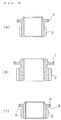
- Fig. 1 shows a shape of work formed in each step.
- a first step i.e., hot forging
- a cylindrical material A is formed into a primary workpiece B by upsetting.
- a matrix having double-stacked large and small diameter portions is upset so as to form the primary workpiece B, which is a rough having a dog gear 1a and a sprocket 2a in the small and large diameter portions, respectively.
- the rough namely, the primary workpiece B does not yet sufficiently assume the detailed shapes of the respective tooth profiles of the dog gear 1a and the sprocket 2a but has a volume distribution simply matched to the volume distribution of the product.
- the primary workpiece B is drawn so as to form a secondary workpiece C whose accuracy is increased in details including the respective tooth profiles of a dog gear 1 and a sprocket 2.
- the secondary workpiece C thus obtained is taken as the product.
- the primary workpiece B (the rough) whose volume distribution is matched to the volume distribution of the product is formed.
- the rough formed in the first step is pressed into a die, whereby the secondary workpiece C is formed by using drawing to increase the accuracy.
- the product formed by this method is considered to be of types as shown in Fig. 2: a type (a) in which the dog gear 1 is separated from the sprocket 2 by a distance equivalent to a clearance for a cutting tool; a type (b) in which the distance required for the clearance for the cutting tool is not secured between the dog gear and the sprocket; a type (c) in which the dog gear is adjacent to and in close contact with the sprocket; and so on.
- the types (a) and (b) of these types are suitable for an alternative to the product formed by cutting.
- the product having the dog gear whose diameter is smaller than the diameter of the sprocket it is not absolutely necessary to provide the clearance for the tool in a boundary between the dog gear and the sprocket.
- the type (c) is not only advantageous in reduction in size of the whole transfer but also greatly increases strength of the dog gear because the root of the dog gear and the matrix have a continuous structure.
- the cylindrical material A is formed into the primary workpiece B by upsetting.
- the matrix having the double-stacked large and small diameter portions is upset so as to form the primary workpiece B, which is the rough having the dog gear 1a and the sprocket 2a in the large and small diameter portions, respectively.
- the rough, namely, the primary workpiece B does not yet sufficiently assume the detailed shapes of the respective tooth profiles of the dog gear 1a and the sprocket 2a but has the volume distribution simply matched to the volume distribution of the product.
- the primary workpiece B is drawn so as to form the secondary workpiece C whose accuracy is increased in details including the tooth profiles.
- a groove 3 is cut in the secondary workpiece C, whereby a worked product D is formed.
- a flange 4 is formed adjacent to the dog gear, whereby the tooth profile is strengthened.
- a not-drawn portion 5 produced in the boundary between the sprocket and the dog gear is removed by cutting the groove 3 (see Fig. 4).
- a margin for drawing is intentionally set in the sprocket, whereby a load to be applied to the die can be reduced.
- the not-drawn portion produced is cut off by utilizing grooving.
- Such a product having the sprocket whose diameter is smaller than the diameter of the dog gear is also considered to be of types (d) to (f) as shown in Fig. 5: the types of the long and short distances between the sprocket 2 and the dog gear 1. Any type can be suitably used for any product and may be used for the product not having the flange 4.
- a drop-in step 6 is formed in the dog gear 1 in the surface close to the sprocket (Fig. 6A), and then the gear tooth of the sprocket 2 is formed so as to enter into the drop-in step 6.
- the cut-in groove 3 is cut off so as to reach to a bottom surface of the drop-in step 6, whereby a finished product can be obtained (Fig. 6B).
- the tooth profile of the sprocket and the bottom surface of the drop-in step have the continuous structure, and the not-drawn portion is formed only in the drop-in step. Consequently, the not-drawn portion is completely cut off by forming the cut-in groove.
- the tooth profile of the dog gear can be reversely tapered, or the product can be lightened by thinning the side surface of the dog gear.
- Forging means is adopted, whereby the dog gear can be formed on an inner wall of a concave groove formed in the side surface of the matrix.
- the first step the rough having the incomplete tooth profiles of the dog gear and the sprocket is formed.
- the accuracy is increased.
- the product having such a shape is further thinned, compared to the product in which the sprocket and the dog gear are axially adjacent to and in close contact with each other.
- the volume distribution of the rough is previously matched to the volume distribution of the product by hot forging tending to have a large amount of deformation.
- drawing is effectively used to increase the accuracy.
- the highly accurate sprocket with dog gear can be formed at low pressure, and various types of products having a large diameter or a small diameter, i.e., including the shapes that cannot be formed by cutting can be manufactured. Therefore, a thickness of the product can be minimized.
- the rough in the first step, is already set so that the volume distribution of the rough may be matched to the volume distribution of the product.
- the second step i.e., a cold forging step
- the amount of deformation is small, thus the load to be applied to the die is reduced, and therefore a longevity of the die is dramatically improved.
- both of the first and second steps adopt the forging means, it is not necessary to consider the clearance for the tool.
- the dog gear and the sprocket are brought close to each other, whereby the product can be axially thinned.
- the not-drawn portion can be produced in the drop-in step, and thus the not-drawn portion is completely removed by forming the cut-in groove.
- the not-drawn portion is produced in the drop-in step.
- the not-drawn portion can be removed when the cut-in groove is formed.
- the load to be applied to the die can be reduced.
Applications Claiming Priority (2)
| Application Number | Priority Date | Filing Date | Title |
|---|---|---|---|
| JP11275199 | 1999-04-20 | ||
| JP11275199A JP3586133B2 (ja) | 1999-04-20 | 1999-04-20 | ドッグギヤ付きスプロケット |
Publications (3)
| Publication Number | Publication Date |
|---|---|
| EP1046441A2 true EP1046441A2 (de) | 2000-10-25 |
| EP1046441A3 EP1046441A3 (de) | 2001-10-31 |
| EP1046441B1 EP1046441B1 (de) | 2004-02-04 |
Family
ID=14594651
Family Applications (1)
| Application Number | Title | Priority Date | Filing Date |
|---|---|---|---|
| EP00106733A Expired - Lifetime EP1046441B1 (de) | 1999-04-20 | 2000-03-29 | Verfahren zur Herstellung eines Ritzels mit Kauenverzahnung |
Country Status (6)
| Country | Link |
|---|---|
| US (1) | US6432017B1 (de) |
| EP (1) | EP1046441B1 (de) |
| JP (1) | JP3586133B2 (de) |
| CA (1) | CA2300689C (de) |
| DE (1) | DE60008035T2 (de) |
| ES (1) | ES2215510T3 (de) |
Cited By (6)
| Publication number | Priority date | Publication date | Assignee | Title |
|---|---|---|---|---|
| US6432017B1 (en) * | 1999-04-20 | 2002-08-13 | O-Oka Corporation | Sprocket with dog gear |
| EP2896471A1 (de) * | 2014-01-17 | 2015-07-22 | Shivam Autotech Ltd. | Verfahren zur Herstellung eines Zahnrads mit Zähnen mit Schmieden |
| CN106352051A (zh) * | 2016-11-30 | 2017-01-25 | 深圳市密姆科技有限公司 | 镶嵌式齿轮 |
| CN107160119A (zh) * | 2017-07-12 | 2017-09-15 | 安徽凯密克企业管理咨询有限公司 | 一种轿车直齿圆锥齿轮冷精锻工艺 |
| CN110270802A (zh) * | 2019-07-05 | 2019-09-24 | 哈尔滨汽轮机厂有限责任公司 | 一种双联齿轮的加工方法 |
| CN111408632A (zh) * | 2020-03-13 | 2020-07-14 | 中铝沈阳有色金属加工有限公司 | 一种锆无氧铜锻棒的加工方法 |
Families Citing this family (19)
| Publication number | Priority date | Publication date | Assignee | Title |
|---|---|---|---|---|
| JP4795543B2 (ja) * | 2001-01-31 | 2011-10-19 | 大岡技研株式会社 | 歯車の製造方法 |
| JP2003098674A (ja) * | 2001-09-21 | 2003-04-04 | Fuji Photo Film Co Ltd | 光重合性平版印刷版 |
| KR100482266B1 (ko) * | 2002-03-04 | 2005-04-14 | 김근화 | 컨베이어용 스프로켓휠의 제조 방법 |
| US6988479B2 (en) * | 2002-04-23 | 2006-01-24 | Cloyes Gear And Products, Inc. | Integrated drive sprocket and gear for balance shaft |
| JP4234366B2 (ja) * | 2002-07-15 | 2009-03-04 | 大岡技研株式会社 | スプライン付きボス部を有するクラッチギヤの製造方法 |
| JP3799549B2 (ja) * | 2002-07-25 | 2006-07-19 | 愛知機械工業株式会社 | 変速装置用ギヤの製造方法 |
| US6981324B2 (en) | 2003-03-26 | 2006-01-03 | American Axle & Manufacturing, Inc. | Method of manufacturing net-shaped gears for a differential assembly |
| JP4907846B2 (ja) * | 2004-03-12 | 2012-04-04 | 大岡技研株式会社 | 歯車、歯車の製造方法および装置 |
| US7174763B2 (en) * | 2005-05-05 | 2007-02-13 | American Axle & Manufacturing, Inc. | Hotformed hubs and method |
| CN101279417B (zh) * | 2008-05-15 | 2010-10-13 | 宁夏天地奔牛实业集团有限公司 | 重型矿用链轮的制造方法 |
| SE534106C2 (sv) * | 2009-09-01 | 2011-05-03 | Scania Cv Ab | Kugghjul |
| CN102069423B (zh) * | 2010-12-12 | 2012-09-26 | 湖北虎牌链条制造有限责任公司 | 一种大型非标准链轮齿形部位加工工艺 |
| DE102011110169B4 (de) * | 2011-08-13 | 2022-10-13 | Volkswagen Aktiengesellschaft | Verfahren zur Herstellung eines Schaltrads für ein Schaltgetriebe |
| KR101393791B1 (ko) * | 2011-09-23 | 2014-05-13 | 현대자동차주식회사 | Bldc모터의 워엄휠 기어 |
| DE102012105123B3 (de) * | 2012-06-13 | 2013-09-12 | Hipp Medical Ag | Fixierungsvorrichtung zum Fixieren von Bruchenden von Knochen einer Knochenfraktur |
| CN102764847B (zh) * | 2012-07-12 | 2014-06-18 | 南昌大学 | 一种直/斜齿柱形齿轮精密成形方法 |
| CN103791059A (zh) * | 2014-02-13 | 2014-05-14 | 长治泽洋锻压机械有限公司 | 一种型材弯曲机的传动装置 |
| CN106352047B (zh) * | 2016-10-08 | 2020-10-30 | 珠海格力节能环保制冷技术研究中心有限公司 | 齿轮 |
| CN115365773B (zh) * | 2022-08-08 | 2024-01-26 | 中国第一汽车股份有限公司 | 一种分动器主动链轮及其加工方法 |
Citations (6)
| Publication number | Priority date | Publication date | Assignee | Title |
|---|---|---|---|---|
| JPS6127138A (ja) * | 1984-07-16 | 1986-02-06 | Goushiyuu Tanzou Kogyosho:Kk | 変速歯車の鍛造法 |
| JPH01127134A (ja) * | 1987-11-09 | 1989-05-19 | Honda Motor Co Ltd | 複合歯車の製造方法 |
| JPH0252139A (ja) * | 1988-08-10 | 1990-02-21 | Honda Motor Co Ltd | 歯車の製造方法 |
| US4938089A (en) * | 1988-01-29 | 1990-07-03 | Ohoka Forge Co Ltd. | Forged gear for a transmission |
| US4939829A (en) * | 1987-07-13 | 1990-07-10 | Honda Giken Kogyo Kabushiki Kaisha | Method of and apparatus for manufacturing a gear |
| EP0552021A1 (de) * | 1992-01-14 | 1993-07-21 | O-Oka Forge Co., Ltd. | Zahnraderzeugnis |
Family Cites Families (3)
| Publication number | Priority date | Publication date | Assignee | Title |
|---|---|---|---|---|
| DE4129149C2 (de) * | 1991-09-02 | 1996-01-11 | Bahr Modultechnik Gmbh | Mit einem Motor verbindbares Zahn- oder Riemenrad |
| US5860882A (en) * | 1996-01-31 | 1999-01-19 | Borg-Warner Automotive, Inc. | Process for manufacturing phased sprocket assemblies by capacitor discharge welding |
| JP3586133B2 (ja) * | 1999-04-20 | 2004-11-10 | 大岡技研株式会社 | ドッグギヤ付きスプロケット |
-
1999
- 1999-04-20 JP JP11275199A patent/JP3586133B2/ja not_active Expired - Lifetime
-
2000
- 2000-02-29 US US09/515,465 patent/US6432017B1/en not_active Expired - Lifetime
- 2000-03-14 CA CA002300689A patent/CA2300689C/en not_active Expired - Lifetime
- 2000-03-29 ES ES00106733T patent/ES2215510T3/es not_active Expired - Lifetime
- 2000-03-29 EP EP00106733A patent/EP1046441B1/de not_active Expired - Lifetime
- 2000-03-29 DE DE60008035T patent/DE60008035T2/de not_active Expired - Lifetime
Patent Citations (6)
| Publication number | Priority date | Publication date | Assignee | Title |
|---|---|---|---|---|
| JPS6127138A (ja) * | 1984-07-16 | 1986-02-06 | Goushiyuu Tanzou Kogyosho:Kk | 変速歯車の鍛造法 |
| US4939829A (en) * | 1987-07-13 | 1990-07-10 | Honda Giken Kogyo Kabushiki Kaisha | Method of and apparatus for manufacturing a gear |
| JPH01127134A (ja) * | 1987-11-09 | 1989-05-19 | Honda Motor Co Ltd | 複合歯車の製造方法 |
| US4938089A (en) * | 1988-01-29 | 1990-07-03 | Ohoka Forge Co Ltd. | Forged gear for a transmission |
| JPH0252139A (ja) * | 1988-08-10 | 1990-02-21 | Honda Motor Co Ltd | 歯車の製造方法 |
| EP0552021A1 (de) * | 1992-01-14 | 1993-07-21 | O-Oka Forge Co., Ltd. | Zahnraderzeugnis |
Non-Patent Citations (3)
| Title |
|---|
| PATENT ABSTRACTS OF JAPAN vol. 010, no. 176 (M-491), 20 June 1986 (1986-06-20) -& JP 61 027138 A (GOUSHIYUU TANZOU KOGYOSHO:KK), 6 February 1986 (1986-02-06) * |
| PATENT ABSTRACTS OF JAPAN vol. 013, no. 373 (M-861), 18 August 1989 (1989-08-18) -& JP 01 127134 A (HONDA MOTOR CO LTD), 19 May 1989 (1989-05-19) * |
| PATENT ABSTRACTS OF JAPAN vol. 014, no. 217 (M-0970), 8 May 1990 (1990-05-08) -& JP 02 052139 A (HONDA MOTOR CO LTD), 21 February 1990 (1990-02-21) * |
Cited By (6)
| Publication number | Priority date | Publication date | Assignee | Title |
|---|---|---|---|---|
| US6432017B1 (en) * | 1999-04-20 | 2002-08-13 | O-Oka Corporation | Sprocket with dog gear |
| EP2896471A1 (de) * | 2014-01-17 | 2015-07-22 | Shivam Autotech Ltd. | Verfahren zur Herstellung eines Zahnrads mit Zähnen mit Schmieden |
| CN106352051A (zh) * | 2016-11-30 | 2017-01-25 | 深圳市密姆科技有限公司 | 镶嵌式齿轮 |
| CN107160119A (zh) * | 2017-07-12 | 2017-09-15 | 安徽凯密克企业管理咨询有限公司 | 一种轿车直齿圆锥齿轮冷精锻工艺 |
| CN110270802A (zh) * | 2019-07-05 | 2019-09-24 | 哈尔滨汽轮机厂有限责任公司 | 一种双联齿轮的加工方法 |
| CN111408632A (zh) * | 2020-03-13 | 2020-07-14 | 中铝沈阳有色金属加工有限公司 | 一种锆无氧铜锻棒的加工方法 |
Also Published As
| Publication number | Publication date |
|---|---|
| US6432017B1 (en) | 2002-08-13 |
| ES2215510T3 (es) | 2004-10-16 |
| CA2300689A1 (en) | 2000-10-20 |
| EP1046441A3 (de) | 2001-10-31 |
| EP1046441B1 (de) | 2004-02-04 |
| DE60008035D1 (de) | 2004-03-11 |
| DE60008035T2 (de) | 2004-09-16 |
| CA2300689C (en) | 2008-02-05 |
| JP2000301281A (ja) | 2000-10-31 |
| JP3586133B2 (ja) | 2004-11-10 |
Similar Documents
| Publication | Publication Date | Title |
|---|---|---|
| EP1046441B1 (de) | Verfahren zur Herstellung eines Ritzels mit Kauenverzahnung | |
| US5125256A (en) | Method of manufacturing outside ring | |
| US4672729A (en) | Method for machining clutch gear for automobile transmission | |
| US7866198B2 (en) | Method of producing a stepped shaft | |
| US20030213125A1 (en) | Ball valve body manufacturing method | |
| JP3787767B2 (ja) | 鍔付き連結シャフトの製造方法 | |
| US4433465A (en) | Process for manufacturing universal joint | |
| JPS6361102B2 (de) | ||
| US3069756A (en) | Method of forming gear blanks | |
| US7823432B2 (en) | Method of forming spring washer blind-holes into a piston for an automobile transmission | |
| EP1371431A2 (de) | Verfahren zum Herstellen von Elementen eines Treibriemens für stufenlos regelbare Getriebe | |
| US7766575B2 (en) | Internally splined part | |
| EP0277269B1 (de) | Verfahren zur Herstellung eines ein Zahnprofil und eine Nabe aufweisenden Werkstückes | |
| US6558263B1 (en) | Forging method of a hollow part | |
| JP3583614B2 (ja) | 歯車の製造方法 | |
| JP2829270B2 (ja) | 板状製品のプレス自動製造方法 | |
| US20040231447A1 (en) | Gear, and method and apparatus for manufacturing the same | |
| JP3513818B2 (ja) | 座金付きナットの製造方法 | |
| US4051709A (en) | Method of producing connector fittings for pipes | |
| JP2000071047A (ja) | スリーブ弁部材の製造方法 | |
| CN102574252A (zh) | 活塞组件多级形成处理 | |
| RU2135319C1 (ru) | Способ получения глубоких цилиндрических изделий из многогранных заготовок | |
| JPH0771566A (ja) | 歯車及びその製造方法 | |
| JP2851591B2 (ja) | 歯車製造用の圧造工具セット | |
| KR0174782B1 (ko) | 봉부재의 헤드부 홈 냉간단조방법 |
Legal Events
| Date | Code | Title | Description |
|---|---|---|---|
| PUAI | Public reference made under article 153(3) epc to a published international application that has entered the european phase |
Free format text: ORIGINAL CODE: 0009012 |
|
| AK | Designated contracting states |
Kind code of ref document: A2 Designated state(s): AT BE CH CY DE DK ES FI FR GB GR IE IT LI LU MC NL PT SE Kind code of ref document: A2 Designated state(s): DE ES FR GB IT |
|
| AX | Request for extension of the european patent |
Free format text: AL;LT;LV;MK;RO;SI |
|
| PUAL | Search report despatched |
Free format text: ORIGINAL CODE: 0009013 |
|
| RIC1 | Information provided on ipc code assigned before grant |
Free format text: 7B 21K 1/30 A, 7B 23P 15/14 B, 7F 16H 55/17 B |
|
| AK | Designated contracting states |
Kind code of ref document: A3 Designated state(s): AT BE CH CY DE DK ES FI FR GB GR IE IT LI LU MC NL PT SE |
|
| AX | Request for extension of the european patent |
Free format text: AL;LT;LV;MK;RO;SI |
|
| 17P | Request for examination filed |
Effective date: 20020121 |
|
| AKX | Designation fees paid |
Free format text: DE ES FR GB IT |
|
| 17Q | First examination report despatched |
Effective date: 20020607 |
|
| RTI1 | Title (correction) |
Free format text: METHOD FOR MANUFACTURING A SPROCKET WITH DOG GEAR |
|
| GRAH | Despatch of communication of intention to grant a patent |
Free format text: ORIGINAL CODE: EPIDOS IGRA |
|
| RTI1 | Title (correction) |
Free format text: METHOD FOR MANUFACTURING A SPROCKET WITH DOG GEAR |
|
| GRAS | Grant fee paid |
Free format text: ORIGINAL CODE: EPIDOSNIGR3 |
|
| GRAA | (expected) grant |
Free format text: ORIGINAL CODE: 0009210 |
|
| AK | Designated contracting states |
Kind code of ref document: B1 Designated state(s): DE ES FR GB IT |
|
| REG | Reference to a national code |
Ref country code: GB Ref legal event code: FG4D |
|
| REF | Corresponds to: |
Ref document number: 60008035 Country of ref document: DE Date of ref document: 20040311 Kind code of ref document: P |
|
| ET | Fr: translation filed | ||
| REG | Reference to a national code |
Ref country code: ES Ref legal event code: FG2A Ref document number: 2215510 Country of ref document: ES Kind code of ref document: T3 |
|
| PLBE | No opposition filed within time limit |
Free format text: ORIGINAL CODE: 0009261 |
|
| STAA | Information on the status of an ep patent application or granted ep patent |
Free format text: STATUS: NO OPPOSITION FILED WITHIN TIME LIMIT |
|
| 26N | No opposition filed |
Effective date: 20041105 |
|
| PGFP | Annual fee paid to national office [announced via postgrant information from national office to epo] |
Ref country code: ES Payment date: 20080325 Year of fee payment: 9 |
|
| PGFP | Annual fee paid to national office [announced via postgrant information from national office to epo] |
Ref country code: GB Payment date: 20080331 Year of fee payment: 9 |
|
| GBPC | Gb: european patent ceased through non-payment of renewal fee |
Effective date: 20090329 |
|
| PG25 | Lapsed in a contracting state [announced via postgrant information from national office to epo] |
Ref country code: GB Free format text: LAPSE BECAUSE OF NON-PAYMENT OF DUE FEES Effective date: 20090329 |
|
| REG | Reference to a national code |
Ref country code: ES Ref legal event code: FD2A Effective date: 20090330 |
|
| PG25 | Lapsed in a contracting state [announced via postgrant information from national office to epo] |
Ref country code: ES Free format text: LAPSE BECAUSE OF NON-PAYMENT OF DUE FEES Effective date: 20090330 |
|
| REG | Reference to a national code |
Ref country code: FR Ref legal event code: PLFP Year of fee payment: 17 |
|
| PG25 | Lapsed in a contracting state [announced via postgrant information from national office to epo] |
Ref country code: IT Free format text: LAPSE BECAUSE OF NON-PAYMENT OF DUE FEES Effective date: 20160329 |
|
| REG | Reference to a national code |
Ref country code: FR Ref legal event code: PLFP Year of fee payment: 18 |
|
| PG25 | Lapsed in a contracting state [announced via postgrant information from national office to epo] |
Ref country code: IT Free format text: LAPSE BECAUSE OF NON-PAYMENT OF DUE FEES Effective date: 20160329 |
|
| PGRI | Patent reinstated in contracting state [announced from national office to epo] |
Ref country code: IT Effective date: 20170710 |
|
| REG | Reference to a national code |
Ref country code: FR Ref legal event code: PLFP Year of fee payment: 19 |
|
| PGFP | Annual fee paid to national office [announced via postgrant information from national office to epo] |
Ref country code: FR Payment date: 20190328 Year of fee payment: 20 Ref country code: DE Payment date: 20190329 Year of fee payment: 20 Ref country code: IT Payment date: 20190321 Year of fee payment: 20 |
|
| REG | Reference to a national code |
Ref country code: DE Ref legal event code: R071 Ref document number: 60008035 Country of ref document: DE |