EP1045467A1 - Electrode de carbone en couches pour piles électrochimiques - Google Patents
Electrode de carbone en couches pour piles électrochimiques Download PDFInfo
- Publication number
- EP1045467A1 EP1045467A1 EP00101596A EP00101596A EP1045467A1 EP 1045467 A1 EP1045467 A1 EP 1045467A1 EP 00101596 A EP00101596 A EP 00101596A EP 00101596 A EP00101596 A EP 00101596A EP 1045467 A1 EP1045467 A1 EP 1045467A1
- Authority
- EP
- European Patent Office
- Prior art keywords
- layer
- carbon particles
- particles
- carbon
- group
- Prior art date
- Legal status (The legal status is an assumption and is not a legal conclusion. Google has not performed a legal analysis and makes no representation as to the accuracy of the status listed.)
- Granted
Links
Images


Classifications
-
- H—ELECTRICITY
- H01—ELECTRIC ELEMENTS
- H01M—PROCESSES OR MEANS, e.g. BATTERIES, FOR THE DIRECT CONVERSION OF CHEMICAL ENERGY INTO ELECTRICAL ENERGY
- H01M4/00—Electrodes
- H01M4/86—Inert electrodes with catalytic activity, e.g. for fuel cells
- H01M4/90—Selection of catalytic material
- H01M4/92—Metals of platinum group
- H01M4/925—Metals of platinum group supported on carriers, e.g. powder carriers
- H01M4/926—Metals of platinum group supported on carriers, e.g. powder carriers on carbon or graphite
-
- H—ELECTRICITY
- H01—ELECTRIC ELEMENTS
- H01M—PROCESSES OR MEANS, e.g. BATTERIES, FOR THE DIRECT CONVERSION OF CHEMICAL ENERGY INTO ELECTRICAL ENERGY
- H01M4/00—Electrodes
- H01M4/86—Inert electrodes with catalytic activity, e.g. for fuel cells
- H01M4/8605—Porous electrodes
-
- H—ELECTRICITY
- H01—ELECTRIC ELEMENTS
- H01M—PROCESSES OR MEANS, e.g. BATTERIES, FOR THE DIRECT CONVERSION OF CHEMICAL ENERGY INTO ELECTRICAL ENERGY
- H01M4/00—Electrodes
- H01M4/86—Inert electrodes with catalytic activity, e.g. for fuel cells
- H01M4/96—Carbon-based electrodes
-
- H—ELECTRICITY
- H01—ELECTRIC ELEMENTS
- H01M—PROCESSES OR MEANS, e.g. BATTERIES, FOR THE DIRECT CONVERSION OF CHEMICAL ENERGY INTO ELECTRICAL ENERGY
- H01M8/00—Fuel cells; Manufacture thereof
- H01M8/10—Fuel cells with solid electrolytes
- H01M8/1004—Fuel cells with solid electrolytes characterised by membrane-electrode assemblies [MEA]
-
- H—ELECTRICITY
- H01—ELECTRIC ELEMENTS
- H01M—PROCESSES OR MEANS, e.g. BATTERIES, FOR THE DIRECT CONVERSION OF CHEMICAL ENERGY INTO ELECTRICAL ENERGY
- H01M2300/00—Electrolytes
- H01M2300/0017—Non-aqueous electrolytes
- H01M2300/0065—Solid electrolytes
- H01M2300/0082—Organic polymers
-
- Y—GENERAL TAGGING OF NEW TECHNOLOGICAL DEVELOPMENTS; GENERAL TAGGING OF CROSS-SECTIONAL TECHNOLOGIES SPANNING OVER SEVERAL SECTIONS OF THE IPC; TECHNICAL SUBJECTS COVERED BY FORMER USPC CROSS-REFERENCE ART COLLECTIONS [XRACs] AND DIGESTS
- Y02—TECHNOLOGIES OR APPLICATIONS FOR MITIGATION OR ADAPTATION AGAINST CLIMATE CHANGE
- Y02E—REDUCTION OF GREENHOUSE GAS [GHG] EMISSIONS, RELATED TO ENERGY GENERATION, TRANSMISSION OR DISTRIBUTION
- Y02E60/00—Enabling technologies; Technologies with a potential or indirect contribution to GHG emissions mitigation
- Y02E60/30—Hydrogen technology
- Y02E60/50—Fuel cells
-
- Y—GENERAL TAGGING OF NEW TECHNOLOGICAL DEVELOPMENTS; GENERAL TAGGING OF CROSS-SECTIONAL TECHNOLOGIES SPANNING OVER SEVERAL SECTIONS OF THE IPC; TECHNICAL SUBJECTS COVERED BY FORMER USPC CROSS-REFERENCE ART COLLECTIONS [XRACs] AND DIGESTS
- Y10—TECHNICAL SUBJECTS COVERED BY FORMER USPC
- Y10T—TECHNICAL SUBJECTS COVERED BY FORMER US CLASSIFICATION
- Y10T29/00—Metal working
- Y10T29/53—Means to assemble or disassemble
- Y10T29/5313—Means to assemble electrical device
- Y10T29/532—Conductor
- Y10T29/53204—Electrode
Definitions
- This invention relates to electrodes for use in electrochemical cells.
- Electrochemical cells are desirable for various applications, particularly when operated as fuel cells. Fuel cells have been proposed for many applications including electrical vehicular power plants to replace internal combustion engines.
- One fuel cell design uses a solid polymer electrolyte (SPE) membrane or proton exchange membrane (PEM), to provide ion exchange between the cathode and anode.
- SPE solid polymer electrolyte
- PEM proton exchange membrane
- Gaseous and liquid fuels are useable within fuel cells. Examples include hydrogen and methanol, and hydrogen is favored. Hydrogen is supplied to the fuel cell's anode. Oxygen (as air) is the cell oxidant and is supplied to the cell's cathode.
- the electrodes are formed of porous conductive materials, such as woven graphite, graphitized sheets, or carbon paper to enable the fuel to disperse over the surface of the membrane facing the fuel supply electrode.
- porous conductive materials such as woven graphite, graphitized sheets, or carbon paper to enable the fuel to disperse over the surface of the membrane facing the fuel supply electrode.
- a typical fuel cell is described in USPN 5,272,017 and USPN 5,316,871 (Swathirajan et al.).
- Important aspects of a fuel cell include reaction surfaces where electrochemical reactions take place, catalysts which catalyze such reaction, ion conductive media, and mass transport media.
- the cost of power produced by a fuel cell is in part dependent on the cost of the catalyst.
- the cost of power produced by a fuel cell is significantly greater than competitive power generation alternatives, partly because of relatively poor utilization of precious metal catalysts in conventional electrodes.
- power produced from hydrogen-based fuel cells is desirable because hydrogen is environmentally acceptable and hydrogen fuel cells are efficient. Therefore, it is desirable to improve the catalyst utilization in fuel cell assemblies to render fuel cells more attractive for power generation. It is also desirable to improve reactant gas diffusion and movement of product water in the fuel cell.
- an electrode structure comprising a current collector sheet, a first electrode layer, and a second electrode layer.
- the first electrode layer is between the current collector sheet and the second electrode layer.
- the first layer comprises a first group of carbon particles and the second layer comprises a second group of carbon particles.
- the first layer is uncatalyzed or catalyzed with a first group of very finely divided catalytic particles; and the second layer is catalyzed with a second group of very finely divided catalytic particles.
- the weight ratio of catalytic particles to carbon particles of the first layer is less than that of the second layer.
- each one of the carbon particle groups comprises a plurality of the carbon particles having internal and external surfaces defining a plethora of pores within and between the carbon particles.
- the very finely divided catalytic particles are supported on the internal and the external surfaces of the carbon particles.
- the first layer is uncatalyzed and the second layer comprises the carbon particles having very finely divided catalytic particles supported on the internal and the external surfaces of the carbon particles.
- the first group of carbon particles is characterized by a density of 0.1 grams per cubic centimeter or less, corresponding to a volume per gram of at least 10 cubic centimeters per gram.
- the second group of carbon particles is characterized by a pH which is in a range of about 6 to about 9.
- each one of the carbon particle groups is characterized by a pH which is in a range of about 6 to about 9.
- the second group of carbon particles is characterized by an average pore radius which is greater than 5 nanometers.
- Each one of the layers further comprises a proton conductive material intermingled with the carbon particles and the catalytic particles.
- the catalytic particle loading of the second layer is less than about 0.30 mg per cm 2 of electrode surface area.
- the catalytic loading of the first layer is less than that of the second layer, desirably is on the order of up to about 0.15 mg/cm 2 , and preferably is on the order of up to about 0.02 mg/cm 2 .
- the second layer comprises catalytic particles and carbon particles in a weight ratio of about 20:80.
- the proton conductive material constitutes 30 to 35 percent by weight of said second layer, and catalytic and carbon particles constitute the balance.
- the first layer of the electrode is produced by forming a mixture comprising proton-conductive material, a first group of carbon particles, and optimally catalytic particles.
- the mixture is applied to a current collector sheet to form a film.
- the second layer of the electrode is produced by forming a second layer over the first layer, where said second layer comprises proton-conductive material, a second group of carbon particles, and catalytic particles.
- the amount by weight of catalytic particles relative to carbon particles of the second layer is greater than that of the first layer.
- a method of making a combination electrolyte and electrode structure for an electrochemical cell having an electrolyte membrane of solid polymer proton-conductive material and first and second electrodes disposed on either side of the electrolyte membrane. At least one of the electrodes is formed by the method of the invention described above. The electrode produced in this method is then placed on a first surface of the electrolyte membrane such that the second layer faces the membrane. A second electrode is placed on the opposite surface of the membrane and the resulting structure is heated and compressed to adhere the electrodes to the membrane.
- the electrodes are adhered to the membrane by subjecting the assembly to a compressive load and an elevated temperature to result in some of the particles becoming at least partially embedded in the membrane, thereby providing a continuous path for protons to the catalyst site where reaction occurs.
- the first and second groups of carbon particles are the same or different. That is, they may have the same characteristics or differ in at least one characteristic. In the case where both layers are catalyzed, the catalyst of the respective layers may be the same or different.
- the invention provides improved catalyst utilization and improved water management.
- the membrane/electrode assembly of the invention provides relatively high power output with unexpectedly low catalyst loading.
- an electrode structure comprising a current collector sheet and first and second layers of electrode material. Together, the layers improve catalyst utilization and water management. This layered arrangement is particularly useful as a cathode.
- Electrochemical cell 10 with a combination membrane electrolyte and electrode assembly (MEA) 12 incorporated therein is shown in pictorial unassembled form.
- Electrochemical cell 10 is constructed as a fuel cell. However, the invention described herein is applicable to electrochemical cells generally.
- Electrochemical cell 10 comprises stainless steel endplates 14, 16, graphite blocks 18, 20 with openings 22, 24 to facilitate gas distribution, gaskets 26, 28, carbon sheet current collectors 30, 32 with respective connections 31, 33 and the membrane electrolyte and electrode assembly (MEA) 12.
- the two sets of graphite blocks, gaskets, and current collectors namely 18, 26, 30 and 20, 28, 32 are each referred to as respective gas and current transport means 36, 38.
- Anode connection 31 and cathode connection 33 are used to interconnect with an external circuit which may include other fuel cells.
- Electrochemical fuel cell 10 operates with gaseous reactants, one of which is a fuel supplied from fuel source 37, and another is an oxidizer supplied from source 39.
- the gases from sources 37, 39 diffuse through respective gas and current transport means 36 and 38 to opposite sides of the MEA 12.
- FIG. 2 shows a schematic view of the assembly 12 according to the present invention.
- porous electrodes 40 form anode 42 at the fuel side and cathode 44 at the oxygen side.
- Anode 42 is separated from cathode 44 by a solid polymer electrolytic (SPE) membrane 46.
- SPE membrane 46 provides for ion transport to facilitate reactions in the fuel cell 10.
- the electrodes of the invention provide more effective proton transfer by close contact between the electrode and the ionomer membrane to provide essentially continuous polymeric contact for such proton transfer.
- the electrode is inset or at least partially embedded in the membrane.
- the MEA 12 of cell 10 has membrane 46 with spaced apart first and second opposed surfaces 50, 52, a thickness or an intermediate membrane region 53 between surfaces 50, 52.
- Respective electrodes 40 namely anode 42 and cathode 44 are well adhered to membrane 46, at a corresponding one of the surfaces 50, 52.
- respective electrodes 40 (anode 42, cathode 44) further comprise respective first and second Teflonated (polytetrafluoroethylene coated, impregnated) graphite sheets 80, 82, at respective sides of membrane 46.
- the anode active material is disposed between the first surface 50 of the membrane and the first sheet 80; the cathode active material is disposed between the second surface 52 and the second sheet 82.
- SPE membrane 46 of the present invention is well known in the art as an ion conductive material. Such SPE membranes are also referred to as polymer electrolyte membranes (PEM). Typical SPE membranes are described in U.S. Pat. Nos. 4,272,353, 3,134,697, and 5,211,984.
- the SPE membranes or sheets are ion exchange resin membranes.
- the resins include ionic groups in their polymeric structure; one ionic component of which is fixed or retained by the polymeric matrix and at least one other ionic component being a mobile replaceable ion electrostatically associated with the fixed component. The ability of the mobile ion to be replaced under appropriate conditions with other ions imparts ion exchange characteristics to these materials.
- the ion exchange resins can be prepared by polymerizing a mixture of ingredients, one of which contains an ionic constituent.
- One broad class of cation exchange, proton conductive resins is the so-called sulfonic acid cation exchange resin.
- the cation ion exchange groups are hydrated sulfonic acid radicals which are attached to the polymer backbone by sulfonation.
- these ion exchange resins into membranes or sheets is also well known in the art.
- the preferred type is perfluorinated sulfonic acid polymer electrolyte in which the entire membrane structure has ion exchange characteristics.
- These membranes are commercially available, and a typical example of a commercial sulfonated perfluorocarbon, proton conductive membrane is sold by E.I. Dupont de Nemours & Co., under the trade designation Nafion®. Another was developed by Dow Chemical.
- Nafion® is a fluoropolymer, and more specifically, a copolymer which comprises perfluorinated carboxylic or sulfonic acid monomeric units.
- Nafion® polymers and polymer membranes are Nafion® polymers prepared from copolymers of tetrafluoroethylene and perfluorinated monomers containing sulfonic or carboxylic acid groups. The perfluorinated sulfonic copolymer is preferred for the invention.
- the membrane 46 is a cation permeable, proton conductive membrane, having H+ ions as the mobile ion; the fuel gas is hydrogen (or reformate) and the oxidant is oxygen or air.
- the product of the overall cell reaction is water.
- the product water is rejected at the cathode 44 which is the electrode 40 on the oxygen side.
- water escapes by simple flow or by evaporation.
- means may be provided if desired, for collecting the water as it is formed and carrying it away from the cell.
- Water management in the cell is important to the successful long-term operation of the electrochemical fuel cell. Water management techniques and cell designs related thereto are described in U.S. Patent Nos. 5,272,017 ('017) and 5,316,871 ('871), each incorporated herein by reference in its entirety.
- the present invention further improves water management during fuel cell operation, and is also directed to other features such as effective electrode utilization, effective proton transfer between electrodes and the membrane, and good gas diffusion. These features are at least partially enhanced by the improved electrode design of the invention.
- the electrodes of the invention comprise a current collector and electrode active material which engages in cell reactions. Electrochemical reactions in a fuel cell occur in an interface region among the proton conductive ionomer, catalyst, electron-conducting carbon, and the gaseous reactant.
- the electrode should be designed so that the catalyst sites are in intimate contact with the proton exchange membrane, the gaseous reactant, and the electron-conducting carbon.
- a conventional electrode may be made by methods as described in U.S. Pat. Nos. 5,272,017 and 5,316,871 incorporated herein above by reference. This is exemplified by the anode of Figures 2 and 3 .
- catalyzed carbon particles are prepared and then combined with the proton conductive binder in solution with a casting solvent.
- the solution is applied to a Teflonated graphite sheet 80, the casting solvent is evaporated and the remaining layer comprising catalyzed carbon particles and binder is then brought into contact with, and hot-pressed to, the membrane.
- the catalyzed carbon particles 60 are in intimate contact with and adhered to the membrane 46.
- FIG. 4 is a pictorial illustration showing the magnified view of a catalyzed carbon particle 60 with very finely divided catalytic particles 62 carried thereon.
- a proton conductive material 64 is intermingled with particles.
- the new electrode configuration of the invention is described herein for use as a cathode, but is not limited thereby. It is thought to be useable for either an anode or a cathode, and is here demonstrated to be particularly advantageous when used as a cathode.
- the electrode of the invention comprises a current collector sheet 82, a first electrode layer 70, and a second electrode layer 72.
- the first electrode layer 70 is between the current collector sheet 82 and the second layer 72.
- the first electrode layer comprises a first group of carbon particles 60 and the second layer comprises a second group of carbon particles 60.
- the carbon particles of the first and second group may be the same type of carbon particles and have the same physical characteristics as shown in the tables. In another embodiment, the carbon particles of the first and second group are different types of carbon particles and have different characteristics. Characteristics are as defined in Table 2.
- the carbon particles of the first group are uncatalyzed ( Figure 3 ).
- the carbon particles of the first group forming the first layer are catalyzed ( Figure 2 ).
- the catalyst 62 is in the form of very finely divided catalytic particles, and typically are metallic particles as further described below.
- the second layer 72 is catalyzed with finely divided catalytic particles 62.
- the relative content of catalytic 62 and carbon particles 60 of the first and second layers is selected so that the weight ratio of catalytic particles to carbon particles of the first layer 70 is less than that of the second layer 72. It is evident that where the first layer does not contain any catalyst particles and the second layer is catalyzed, this condition will be met. In the embodiment where catalytic particles are included in both layers, the weight ratio of catalytic particles to carbon particles in the second layer is greater than that of the first.
- the carbon particles of the first layer comprise a plurality of internal and external surfaces defining a plethora of pores; and the very finely divided catalytic particles are supported on the internal and external surfaces of the carbon particles ( Figure 4 ).
- the carbon particles 60 are catalyzed with the catalytic particles 62 before being mixed with a proton conductive material 64 to form the first layer.
- the second layer is formed in essentially the same way as the first layer. That is, carbon particles are catalyzed with the catalytic particles and then the catalyzed carbon particles are mixed with the proton conductive material. This mixture is then applied to the first layer in order to form the second layer.
- the catalytic particles are preferably metallic, metals or alloys. Most preferred are noble metal catalysts such as platinum (Pt) and palladium (Pd). In addition, other relatively stable metals can be used, including for alloying. Examples are titanium, ruthenium, rhodium, tungsten, tin or molybdenum.
- the invention provides a method for forming the multilayered electrode, having at least first and second layers.
- the first layer is also referred to as primary layer and the second layer being the main layer.
- the method of making an electrode structure comprises the steps of (a) providing a current collector sheet 82; (b) forming a first layer 70 on the sheet which comprises proton conductive material 64, a first group of carbon particles 60, and optionally catalytic particles 62; and (c) forming a second layer 72 over the first layer, where the second layer comprises proton conductive material 64, a second group of carbon particles 60, and catalytic particles 62.
- the amount by weight of catalytic particles relative to carbon particles of the second layer is greater than that of the first layer.
- step (a) is conducted by forming a first mixture of proton conductive material, a first group of carbon particles; and a first group of finely divided catalytic particles supported on and in the carbon particles; and applying the first mixture onto the surface of the current collector and forming a first film from the mixture.
- step (c) is conducted by forming a second mixture of proton conductive material, a second group of carbon particles and a second group of finely divided catalytic particles supported on and in the carbon particles; and applying the second mixture onto the first layer.
- the membrane electrode assembly is prepared by applying the multi-layer electrode and a counter-electrode to a respective surface of the membrane and then hot-pressing at a temperature and compressive load sufficient to adhere the electrodes to the membrane.
- the active material of the anode 42 is applied to Teflonated graphite sheet 80. Then, the anode active material side carried on sheet 80 is contacted with the first surface 50 of the membrane 46. The multi-layer active material of the cathode 44 on sheet 82 is contacted with second surface 52 of the membrane 46.
- the applied sheets 80, 82 are hot-pressed to the membrane while being heated for a time and at a temperature and compressive load sufficient to soften the membrane 46 and at least partially embed at least a portion of the particles in the membrane to thereby form the first and second electrodes 42, 44.
- the embedded or inset particles are at least partially set in respective surfaces of the membrane although they may not be totally encompassed by the membrane or disposed below its surface.
- the step of heating while pressing is conducted at about 250 to about 1000 pounds per square inch compressive load for about one to about five minutes, and at a temperature of about 280°F (130°C) to about 320°F (160°C). It has been found that a compressive load of about 500 pounds per square inch for about 1 to about 2 minutes at a temperature of about 300°F (about 150°C) is effective.
- the compressive load may vary with time. That is, less load and longer times may be used and the converse also applies.
- the embedding of electrodes into the membrane under pressure provides for a continuous path of proton conductive material from one side of the membrane electrode assembly to the other.
- the intimate intermingling of proton conductive material with catalyst and carbon particles provides a continuous path for protons to the catalyst site where reaction occurs.
- the method also achieves a relative optimum utilization of catalytic particles, including adjacent the membrane at the electrode.
- the proton conductive material and the catalytic and carbon particles, forming the anode and the cathode main (second) layer, are in a weight proportion based on 100 parts, of about 30 to about 70 parts proton conductive material and the balance being catalytic and carbon particles. And, the catalytic and carbon particles are in a proportion based on 100 parts by weight of up to about 20 parts catalytic particles and the balance being carbon particles.
- the cathode primary (first layer) is uncatalyzed or contains a lesser proportion of catalytic particles. The amount is on the order of 0.02 mg/cm 2 catalytic particles. This corresponds to about 5 parts by weight catalytic particles and 95 parts by weight carbon particles.
- the cathode comprises a first layer which contains carbon particles intermingled with proton conductive material; alternatively, the first layer contains carbon particles catalyzed with a low amount of platinum on the order of 0.02 mg/cm 2 (5 weight percent platinum) and the balance carbon.
- This layer generally contains 40 weight percent proton conductive material (Nafion) and the balance, the carbon or catalyzed carbon, on the order of 60 weight percent.
- This layer typically has a thickness of about 10 to about 13 microns.
- the second layer contains carbon particles catalyzed with 20 weight percent platinum.
- the weight proportion of Nafion to catalyzed carbon in the main layer is in a range of 30 to 35 weight percent Nafion (proton conductive material) and 65 to 70 weight percent catalyzed carbon. It is desirable that the carbon exhibit a pH in a slurry constituting the carbon and water of about 6 to 9 pH. Preferably, the pH is greater than 6.5, and is about 6.5 to about 9. It is preferred that the average pore size be equivalent to a radius of greater than 5 nanometers. This represents the average pore size of both mesopores and micropores. It is preferred that the current collector, supporting the primary (first layer) and main (second layer), has a density on the order of 0.3 - 0.35 gm/cm 2 .
- a membrane electrode assembly (MEA) 12 was made.
- the anode was made by conventional means and the cathode electrode was made by the improved method of the invention.
- carbon paper was used for the current collector and supported the active material components of the electrode.
- Nafion® and Teflon® are used.
- Nafion® membrane and Nafion® solution were obtained from DuPont and Solution Technology, respectively.
- Nafion® is a registered trademark of DuPont.
- Teflon® is also a trademark of DuPont.
- Carbon sheets for the current collector were obtained from Spectra Corp. Lawrence, MA, in the thickness range 8 - 11 mils and density varying from 0.26 g/cc to 0.7 g/cc.
- Carbon paper was coated with Teflon by placing it horizontally on a rack and then dipping the paper and rack in a well-stirred Teflon/water mixture for 2 minutes.
- Teflon suspension was prepared by mixing 1 part of Teflon 30 B solution from DuPont with 24 parts of de-ionized water by volume. After drying the sheet at 120°C for 15 - 20 minutes, the paper was sintered at 320°C for 15 minutes and 380°C for 30 - 60 minutes in a muffle oven.
- the Teflon content of the sheet was calculated by weighing the sheet before and after the Teflon treatment. The distribution of Teflon in the carbon sheet was measured using electron microprobe analysis. It was observed that the top portion of the sheet had a higher Teflon content than the bottom side.
- the primary layer consisted of a barrier layer to prevent the penetration of the catalyst slurry into the carbon sheet.
- the slurry for the primary carbon/barrier layer was prepared by mixing 1 g acetylene black (AB) with 5 w/o Pt, 10 g de-ionized water and 13.4 g Nafion solution (5% solution, Solution Technology) in an ultrasonic bath for 2 - 3 minutes to form a thick slurry.
- the sheet After applying a layer of the AB slurry on the top side of a Teflonated carbon sheet using a brush, doctor blade, or spray gun, the sheet was dried under a heat lamp for 15 minutes at 100°C.
- the dry film had a catalyst loading of 0.02 mg/cm 2 , Nafion loading of 40 w/o and carbon black loading of 60 w/o.
- TEM studies revealed the thickness of the primary layer to be 10 - 13 ⁇ m.
- the anode catalyst support was Vulcan XC-72R prepared by conventional means. Carbons used for the cathode catalyst were used both in the as-received and heat treated forms. Heat treatment was done at 1000°C for 1 hour in argon. The carbons were catalyzed with a platinum (Pt) catalyst. The catalyst was prepared by adding an aqueous solution of hexachloroplatinic acid (Johnson Matthey) to a carbon/water mixture followed by agitation for 1 hour. Pt (IV) was then reduced to the metallic state by the addition of an excess of sodium borohydride that was added drop-wise to the carbon slurry.
- Pt platinum
- the membrane electrode assembly with a 25 cm 2 active electrode area was positioned in the single cell test fixture (Electrochem, Inc.) made of graphite.
- the single cell was operated by a Globe-Tech fuel cell test station that controlled the cell potential or current, temperature, pressure, mass flow of gases, and humidification of reactant gases using an IBM PC-based data acquisition and control system.
- the current-voltage curve was recorded with H 2 /air as reactants at 80°C and various gas pressures.
- the reactant stoichiometry was 2.5-3 for air and 1.2 - 1.5 for H 2 .
- cyclic voltammograms (CV) of the MEA were recorded to determine the electrochemical active surface area of the Pt catalyst at the cathode, as described earlier.
- Graphite sheets were used as current collector and gas diffuser after loading them with a wet-proofing agent such as Teflon®.
- Teflon® a wet-proofing agent
- the density of the carbon sheet was also varied. 20 w/o Pt (supported on Vulcan XC-72R carbon) was used as the catalyst and the MEA was made with Nafion 112 membrane and a Pt loading of 0.28 mg/cm 2 /electrode.
- Figure 5 shows the effect of varying the current collector Teflon content on the fuel cell performance. As the Teflon loading is increased, the cell performance drops off at lower current densities.
- the effect of applying a primary carbon layer on the graphite sheet prior to coating the main catalyst layer is shown in Figure 6 .
- the primary layer helps improve the fuel cell performance by densifying the main catalyst layer near the membrane interface.
- the catalyst slurry now does not penetrate the graphite sheet and hence the primary carbon layer (first layer) is an important enabler for the use of low-density carbon sheets that show superior performance as described below.
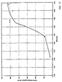
- the maximum current density in the linear region of the current-voltage curve (prior to the sharp drop) increased from 0.6 A/cm 2 to a value as high as 1.8 A/cm 2 at the lowest density of 0.26 g/cc.
- a current collector density of 0.3 to 0.35 g/cc appears to be optimum for cathode applications.
- the catalyst layer needs the proton conducting Nafion polymer in its matrix to ensure good contact of all catalyst particles with the electrolyte.
- the amount of Nafion must be optimized, since any excess can lead to water retention and the consequent flooding of catalyst sites.
- Figure 8 shows the effect of cathode Nafion content on the PEM fuel cell performance. This series of experiments used 20 w/o Pt/Vulcan XC-72R catalyst prepared in house, graphite paper (10 mil, 0.42 g/cc) from SpectraCorp, with Teflon content of 19 w/o. An increase in Nafion content from 20 w/o to 30 w/o (weight percent) saw a dramatic improvement in the fuel cell performance whereas any further increases led to a decrease in cell performance.
- Table 2 lists various physicochemical properties of carbon blacks that are of interest to fuel cell electrode performance. Micropores in carbons have pore sizes less than 2 nm in diameter, whereas mesopores have pore diameters in the range 2-50 nm. Acetylene Black has the highest percentage mesopore area and AX-21 the least. Carbons have both acidic and alkaline pH in the as-received forms, but heat treatment makes them all alkaline.
- Ketjen Black and Black Pearls 2000 carbons have the highest pH and Raven 5000 the lowest pH in the as-received form. Also of interest in electrode fabrication is the density of carbon particles and the pore volume available for gas diffusion. This may be assessed from the volume of 1 gram of carbon black loaded with 10 w/o Pt and shown in Figure 9 . Acetylene Black and Raven 5000 had the highest and the lowest carbon volumes, respectively. Vulcan XC-72R, Ketjen Black, Printex, and Black Pearls 2000 had similar pore volumes.
- Figure 10 gives the fuel cell performance for the various as-received and heat treated carbon blacks. Though these experiments were not carried out with the optimum current collector thickness or Teflon loading, they show an important trend in the results that could be correlated with the hydrophobicity of the supports. Unlike in the ambient case, when KB emerged as clearly the best, the high temperature and pressure experiments show that Acetylene Black, Ketjen Black and Vulcan XC-72R show similar performances. Heat treatment of Acetylene Black, Ketjen Black, Printex and Vulcan XC-72R resulted in a drop in cell performance compared to the as-received carbons.
- Vulcan XC-72R was subjected to various physical treatments such as ball milling, heat treatment, and a combination of ball mill and heat treatment and the results are shown in Figure 11 .
- Ball milling the Vulcan XC-72R or the combination of ball milling/heating resulted in a 40% drop in cell performance.
- One possible explanation could be the decrease in carbon volume (by 60%) and the average pore radius (by 30%) due to ball milling that may have led to mass transport limitations.
- the pH of the primary carbon layer (first layer) was not varied, since acetylene black (AB) had an optimum pH for a semi-hydrophobic support. Also, the optimum pH range for the primary layer (first layer) is unlikely to be very different from the main or catalyst layer (second layer).
- the optimum pore radius for the primary layer may be similar to, and need not be different from the catalyst layer.
- the carbon volume per unit mass is thought to be important.
- AB has the lowest density and hence the highest volume per gram ( Figure 9 ).
- AB will ensure the mechanical blocking of pores in the carbon sheet without appreciably impeding gas transport through the pores in the primary layer.
- these carbon particles are characterized by a volume per gram of at least about 10 cm 3 /gm. This corresponds to a density of about 0.1 gm/cm 3 or less for the carbon particles of the primary layer.
- catalysts may optionally be included in the primary layer (first layer) it is not necessary, since it is unlikely that the reaction zone would extend beyond the main or catalyst layer (second layer).
- the addition of trace amounts of catalysts does improve the conductivity of the matrix and thus facilitates cell performance. Since an ultralow loading of 0.02 mg/cm 2 was sufficient to yield the benefit, an amount of this magnitude is adequate and there appears to be no useful purpose to increase the loading further. It is thought that a range on the order of zero up to 0.15 mg/cm 2 is adequate.
- the present invention improves a vital component of the PEM fuel cell which includes the membrane-electrode assembly (MEA) comprising a membrane sandwiched between two carbon sheet current collectors carrying catalyst layers for the fuel cell reactions.
- MEA membrane-electrode assembly
- the features described herein improve removal of product water and enhance the rate of oxygen transport to the reaction sites at the membrane/electrode interface. This is accomplished by careful optimization of the design and structure of the air electrode (cathode): the graphite paper density and its Teflon content; the Nafion loading in the reaction layer; and the pore distribution and slurry pH of the carbon support used to disperse the catalysts. These features improve catalyst dispersion, gas transport to the catalyst layer, and water management.
- Nafion in the electrode acts as a binder as well as the proton-conducting electrolyte in the catalyst layer.
- Carbon supports were investigated earlier for cells operated at room temperature and near atmospheric pressure. Ketjen Black at the cathode and ball milled Vulcan XC-72R at the anode were found to be the best carbon black supports for dispersing platinum catalyst and for optimum water management (U.S. Patent Nos. 5,272,017 and 5,316,817).
- the method of making the membrane electrode assembly involves coating the membrane with platinized carbon slurry and then attaching a carbon sheet as current collector to the membrane. This had the drawback of being suitable mainly for thick membranes with high equivalent weight such as Nafion 117.
- the method of U.S. Patent Nos. 5,272,017 and 5,316,817 involves applying the catalyzed carbon slurry directly on the carbon sheet followed by hot pressing the electrodes to a membrane.
- the present approach uses a multilayered electrode structure that can be readily adapted for mass production and also for any type of proton exchange membrane or carbon sheet for the gas diffusion backing.
- the multilayered cathode structure consisted of a primary carbon black layer with ultralow amounts of Pt (0.02 mg/cm 2 ) and a main primary catalyst layer of a suitably treated carbon black loaded with 20 w/o Pt.
- the primary layer improved the coatability of the main catalyst layer and helped improve the cell performance by localizing the layer closer to the membrane interface.
- the main catalyst layer performance was optimized with carbon supports that had adequate hydrophobicity to reject water from the electrode matrix, but sufficient hydrophobicity to disperse the Pt catalyst for high catalyst utilization.
- the loading of Nafion polymer in the main catalyst layer, and Teflon polymer in the carbon sheet current collector were also optimized for better gas distribution and catalyst utilization.
- Carbon sheets with densities in the range 0.3 to 0.35 g/cc and Teflon content less than 5 w/o were found to be optimum for the current collector.
- Cathode Nafion content of 30 to 35 w/o yielded acceptable Pt utilization while keeping electrode flooding to the minimum.
- carbons with average pore radii greater than 5 nm and a slurry pH in the neutral range 6 - 9 were found to be best suited for cathode applications.
Landscapes
- Chemical & Material Sciences (AREA)
- Chemical Kinetics & Catalysis (AREA)
- Electrochemistry (AREA)
- General Chemical & Material Sciences (AREA)
- Engineering & Computer Science (AREA)
- Manufacturing & Machinery (AREA)
- Life Sciences & Earth Sciences (AREA)
- Sustainable Development (AREA)
- Sustainable Energy (AREA)
- Materials Engineering (AREA)
- Inert Electrodes (AREA)
- Fuel Cell (AREA)
- Electrodes For Compound Or Non-Metal Manufacture (AREA)
- Electrolytic Production Of Non-Metals, Compounds, Apparatuses Therefor (AREA)
Applications Claiming Priority (2)
| Application Number | Priority Date | Filing Date | Title |
|---|---|---|---|
| US09/290,206 US6277513B1 (en) | 1999-04-12 | 1999-04-12 | Layered electrode for electrochemical cells |
| US290206 | 1999-04-12 |
Publications (2)
| Publication Number | Publication Date |
|---|---|
| EP1045467A1 true EP1045467A1 (fr) | 2000-10-18 |
| EP1045467B1 EP1045467B1 (fr) | 2003-08-20 |
Family
ID=23114970
Family Applications (1)
| Application Number | Title | Priority Date | Filing Date |
|---|---|---|---|
| EP00101596A Expired - Lifetime EP1045467B1 (fr) | 1999-04-12 | 2000-01-27 | Electrode de carbone en couches pour piles électrochimiques |
Country Status (5)
| Country | Link |
|---|---|
| US (1) | US6277513B1 (fr) |
| EP (1) | EP1045467B1 (fr) |
| JP (1) | JP3650567B2 (fr) |
| CA (1) | CA2297316C (fr) |
| DE (1) | DE60004594T2 (fr) |
Cited By (12)
| Publication number | Priority date | Publication date | Assignee | Title |
|---|---|---|---|---|
| WO2001059859A1 (fr) * | 2000-02-08 | 2001-08-16 | Johnson Matthey Public Limited Company | Structure d'anode dotee d'un composant a base de carbone presentant une faible resistance a la corrosion |
| WO2002035624A2 (fr) * | 2000-10-21 | 2002-05-02 | Ballard Power Systems Inc. | Ensemble electrode a membrane, a structure d'electrode optimisee |
| WO2002073723A1 (fr) * | 2001-03-08 | 2002-09-19 | Matsushita Electric Industrial Co., Ltd. | Pile a combustible d'electrolyte polymere |
| FR2826781A1 (fr) * | 2001-06-29 | 2003-01-03 | Commissariat Energie Atomique | Assemblage de pile a combustible a diffuseur bicouche et procede de creation |
| WO2003026035A2 (fr) * | 2001-09-18 | 2003-03-27 | Ballard Power Systems Inc. | Unite d'electrodes a membrane destinee a une pile a combustible a humidification automatique |
| WO2004045011A2 (fr) * | 2002-11-12 | 2004-05-27 | General Motors Corporation | Revetement anticorrosion a conductivite electrique et thermique destine a de multiples applications |
| WO2008101635A1 (fr) * | 2007-02-21 | 2008-08-28 | Solvicore Gmbh & Co. Kg | Procédé de dépôt électrochimique de particules de catalyseur sur des substrats renfermant des fibres de carbone et appareil afférent |
| US7700211B2 (en) | 2002-04-17 | 2010-04-20 | Nec Corporation | Fuel cell, fuel cell electrode and method for fabricating the same |
| EP2360760A4 (fr) * | 2008-12-16 | 2012-06-20 | Cataler Corp | Couche de catalyseur d'anode pour pile à combustible à polymère solide |
| WO2013109283A1 (fr) * | 2012-01-20 | 2013-07-25 | Utc Power Corporation | Électrode de pile à combustible à structure de catalyseur en gradient |
| WO2018206491A1 (fr) * | 2017-05-08 | 2018-11-15 | Bayerische Motoren Werke Aktiengesellschaft | Utilisation d'un matériau carbone électriquement conducteur |
| CN112106242A (zh) * | 2017-11-16 | 2020-12-18 | 日清纺控股株式会社 | 正极、膜电极组件和电池 |
Families Citing this family (47)
| Publication number | Priority date | Publication date | Assignee | Title |
|---|---|---|---|---|
| ATE285625T1 (de) * | 1999-04-30 | 2005-01-15 | Du Pont | Elektrochemische anwendungen von amorphen fluoropolymeren |
| US6238534B1 (en) * | 1999-05-14 | 2001-05-29 | 3M Innovative Properties Company | Hybrid membrane electrode assembly |
| JP3640608B2 (ja) * | 2000-10-16 | 2005-04-20 | 本田技研工業株式会社 | 燃料電池における集電構造 |
| JP2004513529A (ja) * | 2000-11-09 | 2004-04-30 | エフオーシー フランケンブルク オイル カンパニー エスト. | スーパーキャパシタおよび当該スーパーキャパシタを製造する方法 |
| DE10112232A1 (de) * | 2001-03-07 | 2002-09-19 | Deutsch Zentr Luft & Raumfahrt | Verfahren zur Herstellung einer mehrschichtigen Elektrode oder Elektrodenverbundeinheit und Gasdiffusionselektrode |
| US6593023B2 (en) * | 2001-04-27 | 2003-07-15 | The Gillette Company | Battery and method of making the same |
| US6998188B2 (en) * | 2002-02-19 | 2006-02-14 | Petillo Phillip J | Fuel cell components |
| WO2003088386A1 (fr) * | 2002-04-17 | 2003-10-23 | Nec Corporation | Pile a combustible, electrode pour pile a combustible et procede de fabrication de celles-ci |
| WO2003088397A1 (fr) * | 2002-04-17 | 2003-10-23 | Nec Corporation | Pile a combustible, electrode pour pile a combustible et procede de preparation correspondant |
| US7179553B2 (en) * | 2002-09-06 | 2007-02-20 | General Motors Corporation | Method for detecting electrical defects in membrane electrode assemblies |
| US7312174B2 (en) * | 2002-09-09 | 2007-12-25 | The Board Of Trustees Of The University Of Illinois | Method for preparing highly loaded, highly dispersed platinum metal on a carbon substrate |
| US7960072B2 (en) * | 2003-04-04 | 2011-06-14 | GM Global Technology Operations LLC | MEA with catalyst for oxidation of carbon monoxide |
| US7432221B2 (en) * | 2003-06-03 | 2008-10-07 | Korea Institute Of Energy Research | Electrocatalyst for fuel cells using support body resistant to carbon monoxide poisoning |
| US20050064260A1 (en) * | 2003-09-19 | 2005-03-24 | Jsr Corporation | Membrane-electrode structure for solid polymer fuel cell |
| US7955758B2 (en) * | 2004-01-22 | 2011-06-07 | GM Global Technology Operations LLC | Membrane electrode assembly prepared by direct spray of catalyst to membrane |
| US20060204831A1 (en) * | 2004-01-22 | 2006-09-14 | Yan Susan G | Control parameters for optimizing MEA performance |
| KR100721640B1 (ko) * | 2004-01-26 | 2007-05-23 | 마쯔시다덴기산교 가부시키가이샤 | 막촉매층 접합체, 막전극 접합체 및 고분자 전해질형연료전지 |
| TWI276654B (en) * | 2004-02-18 | 2007-03-21 | Ind Tech Res Inst | Proton exchange membrane (PEM) with different molecular permeation rates |
| JP4478009B2 (ja) * | 2004-03-17 | 2010-06-09 | 日東電工株式会社 | 燃料電池 |
| US7648788B2 (en) † | 2004-04-28 | 2010-01-19 | Nissan Motor Co., Ltd. | Membrane-electrode assembly for fuel cell and fuel cell using same |
| KR100951345B1 (ko) * | 2005-02-18 | 2010-04-08 | 지엠 글로벌 테크놀러지 오퍼레이션스, 인코포레이티드 | 연료전지용 내산화성 전극 |
| US20060199061A1 (en) * | 2005-03-02 | 2006-09-07 | Fiebig Bradley N | Water management in bipolar electrochemical cell stacks |
| US7399549B2 (en) * | 2005-04-22 | 2008-07-15 | Gm Global Technology Operations, Inc. | Altering zeta potential of dispersions for better HCD performance and dispersion stability |
| US7767330B2 (en) | 2005-05-04 | 2010-08-03 | Gm Global Technology Operations, Inc. | Conductive matrices for fuel cell electrodes |
| US20070037041A1 (en) | 2005-08-12 | 2007-02-15 | Gm Global Technology Operations, Inc. | Electrocatalyst Supports for Fuel Cells |
| US20070059580A1 (en) * | 2005-09-15 | 2007-03-15 | Budinski Michael K | Design strategies for corrosion mitigation |
| US20070178341A1 (en) * | 2006-01-27 | 2007-08-02 | Christian Wieser | Gas channel coating with water-uptake related volume change for influencing gas velocity |
| US7955750B2 (en) * | 2006-02-21 | 2011-06-07 | GM Global Technology Operations LLC | Controlled electrode overlap architecture for improved MEA durability |
| US8343452B2 (en) * | 2006-03-20 | 2013-01-01 | GM Global Technology Operations LLC | Acrylic fiber bonded carbon fiber paper as gas diffusion media for fuel cell |
| US7687185B2 (en) * | 2006-07-24 | 2010-03-30 | Gm Global Technology Operations, Inc. | Using sacrificial material to mitigate catalyst support corrosion in fuel cell electrode |
| US7569299B2 (en) | 2006-07-25 | 2009-08-04 | Gm Global Technology Operations, Inc. | Multi-component fuel cell gasket for low temperature sealing and minimal membrane contamination |
| US7749632B2 (en) | 2006-07-27 | 2010-07-06 | Gm Global Technology Operations, Inc. | Flow shifting coolant during freeze start-up to promote stack durability and fast start-up |
| US7883810B2 (en) * | 2006-11-09 | 2011-02-08 | GM Global Technology Operations LLC | Slow purge for improved water removal, freeze durability, purge energy efficiency and voltage degradation due to shutdown/startup cycling |
| JP5121290B2 (ja) * | 2007-04-17 | 2013-01-16 | 新日鐵住金株式会社 | 固体高分子形燃料電池電極用触媒 |
| US9056449B2 (en) * | 2007-10-01 | 2015-06-16 | Intelligent Energy Limited | Methods of manufacturing electrochemical cells |
| US8168340B2 (en) | 2007-11-07 | 2012-05-01 | GM Global Technology Operations LLC | Water removal features for PEMfc stack manifolds |
| US8409769B2 (en) | 2007-12-07 | 2013-04-02 | GM Global Technology Operations LLC | Gas diffusion layer for fuel cell |
| US20100035125A1 (en) * | 2008-08-06 | 2010-02-11 | Gm Global Technology Operations, Inc. | Layered electrode for electrochemical cells |
| US9077009B2 (en) * | 2008-08-12 | 2015-07-07 | General Electric Company | Fuel cell element electrode including layers with varying hydrophobicity |
| FR2958799B1 (fr) * | 2010-04-08 | 2012-09-14 | Pragma Ind | Bandelettes de liaison d'anodes et de cathodes d'un convertisseur electrochimique et convertisseur le comprenant |
| CN105142779A (zh) * | 2013-04-25 | 2015-12-09 | 日产自动车株式会社 | 催化剂及其制造方法以及使用该催化剂的电极催化剂层 |
| JP6156490B2 (ja) | 2013-04-25 | 2017-07-05 | 日産自動車株式会社 | 燃料電池用電極触媒ならびに当該触媒を用いる電極触媒層、膜電極接合体および燃料電池 |
| EP3214679B1 (fr) | 2014-10-29 | 2019-12-25 | Nissan Motor Co., Ltd | Couche de catalyseur d'électrode pour pile à combustible, son procédé de fabrication, et ensemble d'électrodes à membrane et pile à combustible l'utilisant |
| JP6358342B2 (ja) * | 2014-12-26 | 2018-07-18 | 新日鐵住金株式会社 | 金属空気電池用電極 |
| FR3060862A1 (fr) * | 2016-12-20 | 2018-06-22 | Compagnie Generale Des Etablissements Michelin | Procede de fabrication d'assemblage membrane-electrode pour pile a combustible |
| FR3060861A1 (fr) * | 2016-12-20 | 2018-06-22 | Compagnie Generale Des Etablissements Michelin | Procede de fabrication d'assemblage membrane-electrode pour pile a combustible et ligne de fabrication |
| JP6566331B2 (ja) * | 2017-04-17 | 2019-08-28 | パナソニックIpマネジメント株式会社 | 電気化学デバイスの電極触媒層、電気化学デバイスの膜/電極接合体、電気化学デバイス、および電気化学デバイスの電極触媒層の製造方法 |
Citations (4)
| Publication number | Priority date | Publication date | Assignee | Title |
|---|---|---|---|---|
| US4362790A (en) * | 1977-12-28 | 1982-12-07 | Electrochemische Energieconversie, N.V. | Porous electrode |
| JPS584270A (ja) * | 1981-06-29 | 1983-01-11 | Hitachi Maxell Ltd | ガス電極 |
| EP0569062A2 (fr) * | 1992-04-03 | 1993-11-10 | General Motors Corporation | Méthode de fabrication d'assemblages membrane-électrode et assemblages ainsi fabriqués |
| EP0872906A1 (fr) * | 1997-04-18 | 1998-10-21 | De Nora S.P.A. | Electrodes à diffusion gazeuse pour piles à combustible à membrane polymèrique |
Family Cites Families (7)
| Publication number | Priority date | Publication date | Assignee | Title |
|---|---|---|---|---|
| US4876115A (en) | 1987-01-30 | 1989-10-24 | United States Department Of Energy | Electrode assembly for use in a solid polymer electrolyte fuel cell |
| US5211984A (en) | 1991-02-19 | 1993-05-18 | The Regents Of The University Of California | Membrane catalyst layer for fuel cells |
| US5234777A (en) | 1991-02-19 | 1993-08-10 | The Regents Of The University Of California | Membrane catalyst layer for fuel cells |
| US5350643A (en) * | 1992-06-02 | 1994-09-27 | Hitachi, Ltd. | Solid polymer electrolyte type fuel cell |
| US5431800A (en) | 1993-11-05 | 1995-07-11 | The University Of Toledo | Layered electrodes with inorganic thin films and method for producing the same |
| BE1008455A3 (nl) * | 1994-06-07 | 1996-05-07 | Vito | Gasdiffusie elektrode met katalysator voor een elektrochemische cel met vast elektrolyt en werkwijze ter vervaardiging van dergelijke elektrode. |
| US5882810A (en) * | 1996-03-08 | 1999-03-16 | The Dow Chemicalcompany | Active layer for membrane electrode assembly |
-
1999
- 1999-04-12 US US09/290,206 patent/US6277513B1/en not_active Expired - Lifetime
-
2000
- 2000-01-27 EP EP00101596A patent/EP1045467B1/fr not_active Expired - Lifetime
- 2000-01-27 CA CA002297316A patent/CA2297316C/fr not_active Expired - Fee Related
- 2000-01-27 DE DE60004594T patent/DE60004594T2/de not_active Expired - Lifetime
- 2000-04-11 JP JP2000108982A patent/JP3650567B2/ja not_active Expired - Fee Related
Patent Citations (4)
| Publication number | Priority date | Publication date | Assignee | Title |
|---|---|---|---|---|
| US4362790A (en) * | 1977-12-28 | 1982-12-07 | Electrochemische Energieconversie, N.V. | Porous electrode |
| JPS584270A (ja) * | 1981-06-29 | 1983-01-11 | Hitachi Maxell Ltd | ガス電極 |
| EP0569062A2 (fr) * | 1992-04-03 | 1993-11-10 | General Motors Corporation | Méthode de fabrication d'assemblages membrane-électrode et assemblages ainsi fabriqués |
| EP0872906A1 (fr) * | 1997-04-18 | 1998-10-21 | De Nora S.P.A. | Electrodes à diffusion gazeuse pour piles à combustible à membrane polymèrique |
Non-Patent Citations (3)
| Title |
|---|
| GIORGI L ET AL: "Influence of the PTFE content in the diffusion layer of low-Pt loading electrodes for polymer electrolyte fuel cells", ELECTROCHIMICA ACTA,GB,ELSEVIER SCIENCE PUBLISHERS, BARKING, vol. 43, no. 24, 21 August 1998 (1998-08-21), pages 3675 - 3680, XP004132406, ISSN: 0013-4686 * |
| LEE S J ET AL: "Effects of Nafion impregnation on performances of PEMFC electrodes", ELECTROCHIMICA ACTA,GB,ELSEVIER SCIENCE PUBLISHERS, BARKING, vol. 43, no. 24, 21 August 1998 (1998-08-21), pages 3693 - 3701, XP004137725, ISSN: 0013-4686 * |
| PATENT ABSTRACTS OF JAPAN vol. 007, no. 076 (E - 167) 30 March 1983 (1983-03-30) * |
Cited By (26)
| Publication number | Priority date | Publication date | Assignee | Title |
|---|---|---|---|---|
| WO2001059859A1 (fr) * | 2000-02-08 | 2001-08-16 | Johnson Matthey Public Limited Company | Structure d'anode dotee d'un composant a base de carbone presentant une faible resistance a la corrosion |
| WO2002035624A2 (fr) * | 2000-10-21 | 2002-05-02 | Ballard Power Systems Inc. | Ensemble electrode a membrane, a structure d'electrode optimisee |
| WO2002035624A3 (fr) * | 2000-10-21 | 2002-08-08 | Daimler Chrysler Ag | Ensemble electrode a membrane, a structure d'electrode optimisee |
| US6916575B2 (en) | 2001-03-08 | 2005-07-12 | Matsushita Electric Industrial Co., Ltd. | Polymer electrolyte type fuel cell |
| WO2002073723A1 (fr) * | 2001-03-08 | 2002-09-19 | Matsushita Electric Industrial Co., Ltd. | Pile a combustible d'electrolyte polymere |
| FR2826781A1 (fr) * | 2001-06-29 | 2003-01-03 | Commissariat Energie Atomique | Assemblage de pile a combustible a diffuseur bicouche et procede de creation |
| WO2003003490A2 (fr) * | 2001-06-29 | 2003-01-09 | Commissariat A L'energie Atomique | Assemblage de pile a combustible a diffuseur bicouche et procede de creation |
| WO2003003490A3 (fr) * | 2001-06-29 | 2004-01-22 | Commissariat Energie Atomique | Assemblage de pile a combustible a diffuseur bicouche et procede de creation |
| WO2003026035A2 (fr) * | 2001-09-18 | 2003-03-27 | Ballard Power Systems Inc. | Unite d'electrodes a membrane destinee a une pile a combustible a humidification automatique |
| WO2003026035A3 (fr) * | 2001-09-18 | 2003-12-04 | Ballard Power Systems | Unite d'electrodes a membrane destinee a une pile a combustible a humidification automatique |
| US7700211B2 (en) | 2002-04-17 | 2010-04-20 | Nec Corporation | Fuel cell, fuel cell electrode and method for fabricating the same |
| US7261963B2 (en) | 2002-11-12 | 2007-08-28 | General Motors Corporation | Corrosion resistant, electrically and thermally conductive coating for multiple applications |
| WO2004045011A3 (fr) * | 2002-11-12 | 2005-03-03 | Gen Motors Corp | Revetement anticorrosion a conductivite electrique et thermique destine a de multiples applications |
| WO2004045011A2 (fr) * | 2002-11-12 | 2004-05-27 | General Motors Corporation | Revetement anticorrosion a conductivite electrique et thermique destine a de multiples applications |
| DE10393695B4 (de) * | 2002-11-12 | 2011-01-20 | General Motors Corp. (N.D.Ges.D. Staates Delaware), Detroit | Elektrisch leitende Fluidverteilungsplatte und Brennstoffzelle |
| WO2008101635A1 (fr) * | 2007-02-21 | 2008-08-28 | Solvicore Gmbh & Co. Kg | Procédé de dépôt électrochimique de particules de catalyseur sur des substrats renfermant des fibres de carbone et appareil afférent |
| EP2360760A4 (fr) * | 2008-12-16 | 2012-06-20 | Cataler Corp | Couche de catalyseur d'anode pour pile à combustible à polymère solide |
| US9761899B2 (en) | 2012-01-20 | 2017-09-12 | Audi Ag | Fuel cell electrode with gradient catalyst structure |
| WO2013109283A1 (fr) * | 2012-01-20 | 2013-07-25 | Utc Power Corporation | Électrode de pile à combustible à structure de catalyseur en gradient |
| WO2018206491A1 (fr) * | 2017-05-08 | 2018-11-15 | Bayerische Motoren Werke Aktiengesellschaft | Utilisation d'un matériau carbone électriquement conducteur |
| CN110603675A (zh) * | 2017-05-08 | 2019-12-20 | 宝马股份公司 | 导电的碳材料的应用 |
| CN110603675B (zh) * | 2017-05-08 | 2022-09-02 | 宝马股份公司 | 导电的碳材料的应用 |
| CN112106242A (zh) * | 2017-11-16 | 2020-12-18 | 日清纺控股株式会社 | 正极、膜电极组件和电池 |
| US11387465B2 (en) | 2017-11-16 | 2022-07-12 | Nisshinbo Holdings Inc. | Cathode, membrane electrode assembly, and battery |
| CN112106242B (zh) * | 2017-11-16 | 2022-09-06 | 日清纺控股株式会社 | 正极、膜电极组件和电池 |
| US11764366B2 (en) | 2017-11-16 | 2023-09-19 | Nisshinbo Holdings Inc. | Cathode, membrane electrode assembly, and battery |
Also Published As
| Publication number | Publication date |
|---|---|
| CA2297316C (fr) | 2005-08-23 |
| DE60004594T2 (de) | 2004-06-24 |
| US6277513B1 (en) | 2001-08-21 |
| DE60004594D1 (de) | 2003-09-25 |
| JP2000311694A (ja) | 2000-11-07 |
| EP1045467B1 (fr) | 2003-08-20 |
| JP3650567B2 (ja) | 2005-05-18 |
| CA2297316A1 (fr) | 2000-10-12 |
Similar Documents
| Publication | Publication Date | Title |
|---|---|---|
| EP1045467B1 (fr) | Electrode de carbone en couches pour piles électrochimiques | |
| EP0569062B1 (fr) | Méthode de fabrication d'assemblages membrane-électrode et assemblages ainsi fabriqués | |
| CA2368258C (fr) | Substrats de diffusion gazeuse | |
| US6344291B1 (en) | Solid polymer electrolyte-catalyst composite electrode, electrode for fuel cell, and process for producing these electrodes | |
| US6521381B1 (en) | Electrode and membrane-electrode assemblies for electrochemical cells | |
| EP1721355B1 (fr) | Membrane-electrode-assemblage | |
| KR100756498B1 (ko) | 액체연료전지용 발전소자와 그 제조방법 및 그것을 사용한액체연료전지 | |
| EP1519433A1 (fr) | Electrode à diffusion pour pile à combustible | |
| US20040166397A1 (en) | Cathode structure for direct methanol fuel cell | |
| CA2347033A1 (fr) | Impregnation avec des ionomeres de substrats d'electrodes pour obtenir des piles a combustible a performances ameliorees | |
| KR100814852B1 (ko) | 연료 전지용 막-전극 어셈블리, 이의 제조방법, 및 이를포함하는 연료 전지 시스템 | |
| KR101326190B1 (ko) | 연료전지용 막 전극 접합체 및 이를 이용한 연료전지 | |
| CN101978536B (zh) | 膜电极接合体和燃料电池 | |
| JP2006085984A (ja) | 燃料電池用mea、および、これを用いた燃料電池 | |
| KR102299218B1 (ko) | 이오노머-이오노머 지지체 복합체, 이의 제조방법 및 상기 이오노머-이오노머 지지체 복합체를 포함하는 연료전지용 촉매 전극 | |
| WO2008058199A1 (fr) | Couches d'électrocatalyseurs pour piles à combustible et leurs procédés de fabrication | |
| KR100442819B1 (ko) | 비가습 연료에서 작동가능한 연료전지용 전극/전해질 접합체 | |
| Lee et al. | Effects of polyamidoamine dendrimers on the catalytic layers of a membrane electrode assembly in fuel cells | |
| KR100881366B1 (ko) | 연료전지용 기체 확산층 및 이를 이용한 연료전지용 전극 | |
| US20220328847A1 (en) | Catalyst layer, membrane electrode assembly for solid polymer fuel cell, and solid polymer fuel cell | |
| EP4074418A1 (fr) | Catalyseur d'électrode pour pile à combustible, couche de catalyseur d'électrode pour pile à combustible, ensemble électrode/membrane, et pile à combustible | |
| JP3433170B2 (ja) | 固体高分子型燃料電池 | |
| KR100696672B1 (ko) | 혼합 주입형 연료 전지용 스택 및 이를 포함하는 혼합주입형 연료 전지 시스템 | |
| KR20200013993A (ko) | 막-전극 접합체, 연료 전지 및 막-전극 접합체의 제조방법 | |
| KR20080008605A (ko) | 연료전지용 막-전극 어셈블리, 이의 제조방법, 및 이를포함하는 연료전지 시스템 |
Legal Events
| Date | Code | Title | Description |
|---|---|---|---|
| PUAI | Public reference made under article 153(3) epc to a published international application that has entered the european phase |
Free format text: ORIGINAL CODE: 0009012 |
|
| 17P | Request for examination filed |
Effective date: 20000127 |
|
| AK | Designated contracting states |
Kind code of ref document: A1 Designated state(s): DE FR GB IT |
|
| AX | Request for extension of the european patent |
Free format text: AL;LT;LV;MK;RO;SI |
|
| 17Q | First examination report despatched |
Effective date: 20010228 |
|
| AKX | Designation fees paid |
Free format text: DE FR GB IT |
|
| GRAH | Despatch of communication of intention to grant a patent |
Free format text: ORIGINAL CODE: EPIDOS IGRA |
|
| GRAS | Grant fee paid |
Free format text: ORIGINAL CODE: EPIDOSNIGR3 |
|
| GRAA | (expected) grant |
Free format text: ORIGINAL CODE: 0009210 |
|
| AK | Designated contracting states |
Designated state(s): DE FR GB IT |
|
| PG25 | Lapsed in a contracting state [announced via postgrant information from national office to epo] |
Ref country code: FR Free format text: LAPSE BECAUSE OF FAILURE TO SUBMIT A TRANSLATION OF THE DESCRIPTION OR TO PAY THE FEE WITHIN THE PRESCRIBED TIME-LIMIT Effective date: 20030820 |
|
| REG | Reference to a national code |
Ref country code: GB Ref legal event code: FG4D |
|
| REF | Corresponds to: |
Ref document number: 60004594 Country of ref document: DE Date of ref document: 20030925 Kind code of ref document: P |
|
| PG25 | Lapsed in a contracting state [announced via postgrant information from national office to epo] |
Ref country code: GB Free format text: LAPSE BECAUSE OF NON-PAYMENT OF DUE FEES Effective date: 20040127 |
|
| PLBE | No opposition filed within time limit |
Free format text: ORIGINAL CODE: 0009261 |
|
| STAA | Information on the status of an ep patent application or granted ep patent |
Free format text: STATUS: NO OPPOSITION FILED WITHIN TIME LIMIT |
|
| 26N | No opposition filed |
Effective date: 20040524 |
|
| EN | Fr: translation not filed | ||
| GBPC | Gb: european patent ceased through non-payment of renewal fee |
Effective date: 20040127 |
|
| PGFP | Annual fee paid to national office [announced via postgrant information from national office to epo] |
Ref country code: IT Payment date: 20070519 Year of fee payment: 8 |
|
| PG25 | Lapsed in a contracting state [announced via postgrant information from national office to epo] |
Ref country code: IT Free format text: LAPSE BECAUSE OF NON-PAYMENT OF DUE FEES Effective date: 20080127 |
|
| PGFP | Annual fee paid to national office [announced via postgrant information from national office to epo] |
Ref country code: DE Payment date: 20190115 Year of fee payment: 20 |
|
| REG | Reference to a national code |
Ref country code: DE Ref legal event code: R071 Ref document number: 60004594 Country of ref document: DE |