EP1044154B1 - Vorrichtung zum umwandeln eines geschuppten haufens aus gegenständen in eine schuppenformation - Google Patents
Vorrichtung zum umwandeln eines geschuppten haufens aus gegenständen in eine schuppenformation Download PDFInfo
- Publication number
- EP1044154B1 EP1044154B1 EP98960981A EP98960981A EP1044154B1 EP 1044154 B1 EP1044154 B1 EP 1044154B1 EP 98960981 A EP98960981 A EP 98960981A EP 98960981 A EP98960981 A EP 98960981A EP 1044154 B1 EP1044154 B1 EP 1044154B1
- Authority
- EP
- European Patent Office
- Prior art keywords
- conveyor
- displacement
- formation
- conveying
- conveying direction
- Prior art date
- Legal status (The legal status is an assumption and is not a legal conclusion. Google has not performed a legal analysis and makes no representation as to the accuracy of the status listed.)
- Expired - Lifetime
Links
- 230000001131 transforming effect Effects 0.000 title 1
- 238000006073 displacement reaction Methods 0.000 claims description 51
- 230000015572 biosynthetic process Effects 0.000 claims description 31
- 238000011144 upstream manufacturing Methods 0.000 claims description 10
- 229910000639 Spring steel Inorganic materials 0.000 description 8
- 230000001154 acute effect Effects 0.000 description 1
- 238000010276 construction Methods 0.000 description 1
- 230000007423 decrease Effects 0.000 description 1
- 230000001419 dependent effect Effects 0.000 description 1
- 239000013013 elastic material Substances 0.000 description 1
- 230000001788 irregular Effects 0.000 description 1
- 230000036316 preload Effects 0.000 description 1
- 230000000452 restraining effect Effects 0.000 description 1
Images

Classifications
-
- B—PERFORMING OPERATIONS; TRANSPORTING
- B65—CONVEYING; PACKING; STORING; HANDLING THIN OR FILAMENTARY MATERIAL
- B65H—HANDLING THIN OR FILAMENTARY MATERIAL, e.g. SHEETS, WEBS, CABLES
- B65H29/00—Delivering or advancing articles from machines; Advancing articles to or into piles
- B65H29/66—Advancing articles in overlapping streams
- B65H29/6654—Advancing articles in overlapping streams changing the overlapping figure
-
- B—PERFORMING OPERATIONS; TRANSPORTING
- B65—CONVEYING; PACKING; STORING; HANDLING THIN OR FILAMENTARY MATERIAL
- B65H—HANDLING THIN OR FILAMENTARY MATERIAL, e.g. SHEETS, WEBS, CABLES
- B65H5/00—Feeding articles separated from piles; Feeding articles to machines
- B65H5/24—Feeding articles in overlapping streams, i.e. by separation of articles from a pile
-
- B—PERFORMING OPERATIONS; TRANSPORTING
- B65—CONVEYING; PACKING; STORING; HANDLING THIN OR FILAMENTARY MATERIAL
- B65H—HANDLING THIN OR FILAMENTARY MATERIAL, e.g. SHEETS, WEBS, CABLES
- B65H2511/00—Dimensions; Position; Numbers; Identification; Occurrences
- B65H2511/20—Location in space
- B65H2511/22—Distance
Definitions
- the present invention relates to an apparatus for converting a from flat objects accumulating on a first conveyor, in particular Printed products, formed shingled heap into one Imbricated formation.
- a device for increasing the distance between successive products of a scale formation or Converting the scale formation of printed products on a first conveyor operated at a conveying speed fed, with a displacement device individually from a first into a second scale formation and in the effective area of a second Transfer conveyor is known from DE 39 03 610 A1.
- This The device has two disk-shaped disks, each provided with a cam Beams that are driven by shafts that are perpendicular to the Direction of conveyance of the printed products. With every turn of the A single printed product is captured by the cams and disks conveyed. Because the cams running in a circular path are not are carried along the conveying direction of the printed products a relative movement between the Cams and the printed products that are used in capturing and Transporting the print products may be undesirable.
- Each object is individually formed to form the scale formation with positive entrainment to the downstream end of the Work area pushed.
- the number of working strokes per time unit one to grip on the rear edge the resulting objects are certain means of displacement greater than the largest possible number of items accruing per unit of time. This is the scaled at a given conveying speed Heap of given objects, the rear edges of a permissible have a minimum distance. Because the moving means even then, related perform more than one working stroke on a single object, it is ensured that each of the objects is moved individually and a second conveyor that is driven at a higher conveyor speed is fed.
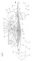
- the device shown in FIGS. 1 and 2 has a first conveyor 10 designed as a belt conveyor, which is driven in the conveying direction F at a first conveying speed v 1 .
- the conveyor belt 12 which is formed from a plurality of endless strips of rubber-elastic material arranged side by side, is guided around deflection rollers 14 and 14 ', respectively.
- the first conveyor 10 is immediately followed by a second conveyor 16, which is also designed as a belt conveyor and whose adjacent conveyor belts 18 are guided at the upstream beginning around deflection wheels which are arranged between the downstream deflection rollers 14 'of the first conveyor 10 and coaxially with them are stored.
- the second conveyor 16 is driven in the conveying direction F at a second conveying speed v 2 which is greater than the first conveying speed v 1 .
- the second conveyor 16 acts on the upstream one Beginning 18 'a pressing element 20 together. This points two in the direction Weight rollers arranged at a distance from the axis of the deflection rollers 14 ' 22, which together with the corresponding conveyor belts 18 form a conveyor gap at the deflection wheels.
- the first conveyor 10 is intended for flat, flexible objects 24, which are arranged in a closely scaled formation - forming a heap of S. are and in which each item on the following is almost complete overlapping to promote. It is in the example shown the objects 24 are thin printed products that are in the closely scaled Formation with minimum distance A between the trailing edges 26 successive objects 24 are arranged.
- a displacement device 28 is arranged above the first conveyor 10. This is intended to successively shift the objects 24 conveyed in the closely scaled heap S by means of the first conveyor 10 one by one in the conveying direction F at a speed v greater than the first conveying speed v 1 and to the effective area 30 of the second conveyor 16 by increasing the distance to the next object supply.
- a scale formation S 1 is thereby formed.
- the effective area 30 of the second conveyor 16 begins at its beginning 18 ', which is defined by the conveyor gap defined by the conveyor belts 18 and the weight rollers 22.
- the enlarged distance between the rear edges 26 of successive objects 24 is designated by B in FIG. 1.
- the displacement device 28 has a running in the conveying direction F, as a guide rail 32 formed guide means 32 '.
- a carriage 34 is freely movable, on the one Sliding means 36 'is arranged.
- This is a bow-like sliding element 36 formed and fixed at one end to the carriage 36.
- the Sliding element 36 is at the free end, as can be seen in particular from the 2 shows a hook 38 which is intended to due to the spring action of the displacement element 36 along the sliding flat overhead 40 of the objects 24 and then with the rear edge 26 of an object 24 in contact to get and this object 24 in the direction of conveyance F under positive To postpone taking.
- the carriage 34 is connected via a rod 42 to a drive 46 designed as a cylinder-piston unit 44.
- a drive 46 designed as a cylinder-piston unit 44.
- This is intended to cyclically move the carriage 34 together with the displacement element 36 from an upstream starting position by a working stroke H in the conveying direction F to an end position indicated by dash-dotted lines and back again.
- the cylinder-piston unit 44 is designed such that it accelerates the displacement element 36 to a constant speed v within a very short section of the stroke H, moves it further at this speed v, and then brakes it again to a standstill within a comparatively very short deceleration section.
- the frequency with which the cylinder-piston unit 44 reciprocates the displacement element 36 in and against the conveying direction is selected in such a way that the displacement element in each case within a period of time which is determined by the quotient from the permissible minimum distance A between the trailing edges 26 in succession, objects 24 transported by the first conveyor 10 and the first conveying speed v 1 executes at least two working strokes in the conveying direction F.
- a working area H 'of the displacement element 36 which is given by that section of the stroke H in which the displacement element 36 is moved at a speed v which is greater than the first conveying speed v 1 , is greater than the permissible minimum distance A.
- the displacement element 36 can catch up the rear edge 26 of an object 24, come to rest against the rear edge 26 and move this object 24 in the conveying direction F at the speed v.
- a reference roller 48 is mounted so as to be freely rotatable, around which an endless belt 50 is guided, which runs around a further roller 52, which is arranged upstream of the reference roller 48 and at a greater distance from the second conveyor 16 than the reference roller 48 is.
- the belt 50 forms, together with the conveyor belt 1 2 of the first conveyor 10, an inlet for the scale-like formation S and forms a reference 54 in the region of the reference roller 48 facing the conveyor belt 12 for the upper edge of the scale-like formation S, as seen in the direction of conveyance F
- Reference roller 48 at least approximately at the upstream start of the stroke H.
- the mutual position of the reference roller 48 and the guide rail 32 - seen at right angles to the conveying direction F - are coordinated with one another in such a way that the hook 38 of the displacement element 36 is preloaded on the flat side 40 of the respective one Object 24 rests when the scale-like formation S is held in contact with the reference 54 by means of the first conveyor 10.
- the conveyor belt 12 is designed to be rubber-elastic to form a corresponding sag and the deflection rollers 14, 14 'are arranged with respect to the reference roller 48 in such a way that the objects 24 definitely come into contact with the belt 50.
- the reference 54 is arranged with respect to the conveying plane defined by the second conveyor 16 such that it is approximately aligned with a plane parallel to the conveying plane and tangent to the formed scale S 1 from above.
- the downstream end of the work area H ' is from the beginning 18 'of the second conveyor 16 spaced a distance C equal to or is insignificantly smaller than the length L measured in the conveying direction F. the objects when they are acted upon by the displacement element 36. How this with the arrow D (Fig. 1) and the position of the dot-dash line shown Sliding device 28 is indicated, the distance C can be corresponding the format of the objects 24 to be processed.
- the first conveyor 10 which is also designed as a belt conveyor, is intended to convey the objects 24 accumulating in a closely scaled pile S, in which each object 24 rests on the preceding one, in the conveying direction F at the first conveying speed v 1 to transport.
- the displacement device 28 is of the same design as in the device 1, but arranged mirrored.
- the one at the free end of the self-bouncing trained displacement element 36 arranged hook 38 is located with preload on the flat side 40 of a respective one that is now downward Item 24.
- the conveyor belt 12 by spaced conveyor belts is formed and the sliding element 36 between two adjacent Conveyor belt is located.
- the in this case not rubber elastic trained conveyor belts run over a reference roller 48, located near the upstream start of the H located.
- the reference roller 48 is opposite a roller 48 'freely rotatable on a pivoted weight lever 56 stored.
- the belt 50 is guided, which in turn together with the conveyor belt 12 an inlet for the scale-like Formation S forms and is the same as in the embodiment shown above prevents the objects 24 from moving ahead Object that by means of the displacement element 36 with greater speed is moved by frictional forces can.
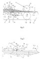
- FIGS. 4 and 5 show an embodiment of the device in which the displacement means 36 'several, in the specific case twenty-two displacement elements 36 has. These are alternately on the two sides a support disk 58 in the circumferential direction along one to the axis 58 ' the support disc concentric circle arranged evenly.
- the support disk 58 sits on a concentric to its axis 58 'on Machine frame freely rotatable drive shaft 60. This is by means of of a drive 46 driven continuously rotating in the direction of rotation D.
- Each displacement element 36 is designed like a double lever and attached to one parallel to the axis 58 ', bearing shaft 58 projecting from the support shaft 62 freely pivoting.
- the sliding element 36 a cross-sectionally U-shaped support member 64, on which the free end to a hook 38 made of spring steel sheet Bracket 36 "is attached.
- On the end facing away from the hook 38 of the support member 64 is a follow-up role on a pin 66 parallel to the bearing shaft 62 68 freely rotatably mounted, which is designed with the lateral surface of a associated control plate 70 attached to the machine frame.
- a tension spring 72 is attached to the pin 66, which in radial direction and is attached to the other side of the support disk.
- the lateral surface of the control disk 70 thus forms a control link 74 for controlling the pivoting position of the displacement elements 36 in dependence from their rotational position about axis 58 '.
- the first conveyor 10, of which the active run 12 ′ of the conveyor belt 12 is shown, runs below the displacement device 28. It is driven in the conveying direction F running perpendicular to the axis 58 'at the first conveying speed v 1 . As in the exemplary embodiments shown further above, it is followed by the second conveyor 16, which is driven at a greater conveying speed v 2 .
- the first conveyor 10 is intended to convey objects 24 arranged in the closely scaled heap S into the effective area of the shifting device 28, which successively shifts the objects 24 one after the other in the conveying direction F at a speed v 1 greater than the first conveying speed v 1 and by increasing the speed Distance to the next object 24 supplies the effective area of the second conveyor 16, whereby a scale formation S 1 is formed.
- a guide device 76 points above the first conveyor 10 and below the support disk 58 on two profile-shaped guide elements 78, which are attached to the machine frame. Both sides of the trajectory of the sliding elements 36 arranged guide elements 78 a rectilinear guide section 78 'running in the conveying direction F and one upstream from it at an obtuse angle adjoining inlet section 78 ". In the free end region of the Inlet section 78 ′′ is essentially on the guide elements 78 rectangular, arranged between the guide elements 78 Spring steel sheet 80 attached to its laterally projecting tab 80 '. It stands in a downward direction over the guide section 78 ' and including this with an acute angle and ending at upstream beginning of work area H '.
- the leadership section 78 ' forms the reference 54 for the trailing edges 26 of the supplied Objects 24 which, as a result of the pretensioning of the first conveyor 10 are held in the upward direction against the guide section 78 '.
- the inlet section 78 ′′ forms together with the first conveyor 10 a wedge-shaped narrowing inlet in the from the active strand 10 'of Conveyor belt 12 and the guide portion 78 'formed gap.
- the control link 74 runs concentrically to the axis 58 'from approximately 2 a.m. - counterclockwise - to approximately 7 a.m.
- the displacement elements 36 are in a position with respect to the circular support disk 58, in which the hook 38 is trailing with respect to the follower roller 68 in the direction of rotation D and the displacement elements 36 enclose an angle of approximately 45 ° to a tangent to the support disk 58.
- a straight link section 74 1 connects tangentially to this area. Since the distance between the link and the axis 58 ′ increases in the direction of rotation D, the displacement elements 36 are pivoted in this area counter to the direction of rotation D.
- displacement elements 36 come to rest with the free end of the hook 38 on the upper side of the spring steel sheet 80 and apply a force in the direction pointing downward.
- a link section 74 2 which has the shape of an elongated S and in which the increase in the distance between the control link 74 and the axis 58 ', initially decreases and then increases again, adjoins the link section 74 1 .
- the relevant displacement element 36 runs off the spring steel sheet 80, comes with the free end of the hook 38 on the flat side 40 above that object 24 on which the spring steel sheet 80 lies flat and then becomes due to the shape of the link section 74 2 pivoted such that the hook 38 in the working section H 'moves at least approximately along a straight line of motion running in the conveying direction F, the bracket 36 ′′ being slightly resiliently pushed back due to the counterforce of the first conveyor 10.
- the hook 38 When moving through the working section H ', the hook 38 comes to rest on the rear edge 26 of an object 24 and moves it in the conveying direction F at a speed v, which is greater than the speed v, of the first conveyor and guides this object while increasing the distance to the rear edge of the next item 24 to the second conveyor 16.
- a speed v which is greater than the speed v, of the first conveyor and guides this object while increasing the distance to the rear edge of the next item 24 to the second conveyor 16.
- the link section 74 2 is followed by a link section 74 3 , in which the distance to the axis 58 ′, seen in the direction of rotation D, increases sharply.
- the beginning of this link section 74 3 coincides with the end of the working area H 'for a displacement element 36.
- the displacement elements 36 are pivoted strongly clockwise in a very short time and the hook 38 in question is lifted out of the movement path of the objects 24.
- the guide sections 78 'of the guide elements 78 prevent the objects 24 under the influence of the Hook 38 can be bent open.
- Lateral hold-down rollers also prevent 82 that the objects 24 in their lateral edge areas can lift.
- the closely scaled pile S is "pulled apart" to form a scale formation S 1 .
- the movement of the displacement element need not be matched to a system cycle with regard to phase position or frequency. However, the condition is that the frequency of the movement of the displacement element is greater than the greatest possible frequency with which the objects can be obtained.
- the displacement means 36 'of the embodiment forms shown in FIGS. 1 to 3 have two displacement elements 36 which are driven in phase opposition at half the frequency, but in the conveying direction F at a higher speed v than the first conveying speed v 1 . It is also conceivable to provide more than two displacement elements.
- the device is particularly suitable for the distance between in one irregular close-scaled formation to falling objects enlarge. Since neither synchronization with a system clock, nor a phase adjustment is necessary, the structure and the drive extremely easy to train.
- the second conveying speed v 2 is preferably approximately 3 to 4 times as large as the first conveying speed v 1 .
- the number of working strokes of the displacement means 36 'per time interval, defined by the quotient of the minimum distance A and the first conveying speed v 1 is advantageously approximately 3 to 4.
- the working range H' is preferably 1, 5, advantageously about 2 to 3 times as large as the minimum distance A.
- the second conveying speed v 2 is predetermined.
- the first conveying speed v 1 is then set in such a way that the displacement means 36 ′ can certainly never detect and move two objects 24 together.
Landscapes
- Engineering & Computer Science (AREA)
- Mechanical Engineering (AREA)
- Separation, Sorting, Adjustment, Or Bending Of Sheets To Be Conveyed (AREA)
- Feeding Of Articles By Means Other Than Belts Or Rollers (AREA)
- Stacking Of Articles And Auxiliary Devices (AREA)
Description
- Fig. 1
- in Seitenansicht eine erste Ausbildungsform der Vorrichtung zum Vergrössern des Abstandes zwischen den Hinterkanten aufeinanderfolgender Gegenstände, die in einer verdichteten schuppenartigen Formation anfallen, in welcher jeder Gegenstand auf dem nachlaufenden aufliegt;
- Fig. 2
- ebenfalls in Seitenansicht und gegenüber Fig. 1 vergrössert einen Teil der dort gezeigten Vorrichtung;
- Fig. 3
- in Seitenansicht einen Teil einer Vorrichtung zum Vergrössern des Abstandes zwischen den Hinterkanten aufeinanderfolgender Gegenstände, die in einer verdichteten schuppenartigen Formation anfallen, in welcher jeder Gegenstand auf dem vorauslaufenden aufliegt;
- Fig. 4
- in Seitenansicht eine weitere Ausbildungsform der erfindungsgemässen Vorrichtung; und
- Fig. 5
- in Draufsicht und teilweise geschnitten die Ausbildungsform gemäss Fig. 4.
Claims (11)
- Vorrichtung zum Umwandeln der Formation von flächigen Gegenständen (24), insbesondere Druckereiprodukten, die auf einem ersten, mit einer ersten Fördergeschwindigkeit (v1) angetriebenen Förderer (10) zugeführt, mit einer Verschiebeeinrichtung (28) einzeln aus einer ersten Formation (S) in eine Schuppenformation (S1) sowie in den Wirkbereich (30) eines zweiten Förderers (16) überführt werden, der mit einer bezüglich der ersten Fördergeschwindigkeit (v1) grösseren zweiten Fördergeschwindigkeit (v2) angetrieben ist, dadurch gekennzeichnet, dass die Verschiebeeinrichtung (28) ein mit einem Haken (38) versehenes Verschiebemittel (36') aufweist, das mittels eines Antriebs (46) und eines Führungsmittels (32') in einem Arbeitsbereich (H') wenigstens annähernd in Förderrichtung (F) des ersten Förderers (10) mit einer Geschwindigkeit (v), die grösser als die erste Fördergeschwindigkeit (v1) ist, zyklisch derart verschiebbar ist, dass die flächigen Gegenstände (24) in der einen geschuppten Haufen bildenden ersten Formation (S) durch den Haken (38) einzeln erfasst und zum zweiten Förderer (16) in die Schuppenformation (51) überführt werden können.
- Vorrichtung nach Anspruch 1, dadurch gekennzeichnet, dass der Antrieb (46) das Verschiebemittel (36') in einer durch den Quotienten aus einem zulässigen minimalen Abstand (A) zwischen den Hinterkanten (26) aufeinanderfolgender Gegenstände (24) im anfallenden Haufen (S) und der ersten Födergeschwindigkeit (v1) bestimmten Zeitdauer mindestens wenigstens annähernd zweimal in Förderrichtung (F) durch den Arbeitsbereich (H') bewegt.
- Vorrichtung nach Anspruch 1 oder 2, dadurch gekennzeichnet, dass der erste Förderer (10) einen Bandförderer aufweist, dessen förderaktives Trum bei Anwesenheit eines Haufens (S) einen derartigen Durchhang bildenden kann, dass der jeweils vom Verschiebemittel (36') zu erfassende Gegenstand (24) sich wenigstens annähernd in einer zur Bewegungsbahn des Verschiebemittels (36') im Arbeitsbereich (H') parallelen Lage befindet.
- Vorrichtung nach einem der Ansprüche 1 bis 3, dadurch gekennzeichnet, dass der Arbeitsbereich (H') des Verschiebemittels (36') vom Wirkbereich (30) des zweiten Förderers (16) in einem Abstand, der wenigstens annähernd der in Förderrichtung (F) gemessenen Länge (L) der Gegenstände (24) entspricht, angeordnet ist.
- Vorrichtung nach einem der Ansprüche 1 bis 4, dadurch gekennzeichnet, dass der Arbeitsbereich (H') grösser als der zulässige minimale Abstand (A) zwischen den Hinterkanten (26) aufeinanderfolgender Gegenstände (24) in der anfallenden Formation (S) ist.
- Vorrichtung nach einem der Ansprüche 1 bis 5, dadurch gekennzeichnet, dass das Verschiebemittel (36') federnd ausgebildet ist, um unter Federvorspannung an der ihm zugewandten Flachseite (40) eines Gegenstandes (24) anzuliegen.
- Vorrichtung nach Anspruch 6, dadurch gekennzeichnet, dass das Verschiebemittel (36') ein an einem wenigstens annähernd in Förderrichtung (F) verlaufenden Führungsmittel (32') geführten Schlitten (34) einerends befestigtes und andernends mit einem Haken (38) versehenes, vorzugsweise selbstfederndes, bügelartiges Verschiebeelement (36) aufweist.
- Vorrichtung nach einem der Ansprüche 1 bis 6, dadurch gekennzeichnet, dass das Verschiebemittel (36') mehrere mit einem Haken (38) versehene, vorzugsweise selbstfedernde, bügelartige Verschiebeelemente (36) aufweist, die entlang einer geschlossenen Umlaufbahn, vorzugsweise Kreisbahn umlaufend angetrieben und in ihrer Schwenklage derart gesteuert sind, dass die Haken (38) beim Hindurchbewegen durch den Arbeitsbereich (H') sich wenigstens annähernd geradlinig und in Förderrichtung (F) bewegen.
- Vorrichtung nach einem der Ansprüche 1 bis 8, dadurch gekennzeichnet, dass der zweite Förderer (16) einen Bandförderer (18) und ein mit diesem am Anfang (18') des Wirkbereichs (30) zusammenwirkendes Andrückelement (20) aufweist, um den jeweils mittels des Verschiebemittels (36') zugeführten Gegenstand (24) mitnahmefest in Richtung gegen den Bandförderer (18) zu drücken.
- Vorrichtung nach einem der Ansprüche 1 bis 9, gekennzeichnet durch ein bezüglich des Führungsmittels (32') fest und stromaufwärts des Arbeitsbereichs (H') angeordnetes Referenzelement (48), das zum Anliegen an der Formation (S), gegebenenfalls über eine bandartige Zwischenlage (12,50), auf der dem Führungsmittel (32') zugewandten Seite bestimmt ist.
- Vorrichtung nach Anspruch 10, gekennzeichnet durch ein mit dem Referenzelement (48) einen an den Haufen (S) anpassbaren Spalt bildendes Andrückmittel (12,48') um die sich im Spalt befindenden Gegenstände (24) an den ersten Förderer (10) mitnahmefest anzudrücken und so gegen Mitnahme in Förderrichtung (F) mit grösserer Geschwindigkeit zu hindern.
Applications Claiming Priority (3)
| Application Number | Priority Date | Filing Date | Title |
|---|---|---|---|
| CH298297 | 1997-12-30 | ||
| CH298297 | 1997-12-30 | ||
| PCT/CH1998/000557 WO1999035071A1 (de) | 1997-12-30 | 1998-12-29 | Vorrichtung zum umwandeln eines geschuppten haufens aus gegenständen in eine schuppenformation |
Publications (2)
| Publication Number | Publication Date |
|---|---|
| EP1044154A1 EP1044154A1 (de) | 2000-10-18 |
| EP1044154B1 true EP1044154B1 (de) | 2002-05-22 |
Family
ID=4246008
Family Applications (1)
| Application Number | Title | Priority Date | Filing Date |
|---|---|---|---|
| EP98960981A Expired - Lifetime EP1044154B1 (de) | 1997-12-30 | 1998-12-29 | Vorrichtung zum umwandeln eines geschuppten haufens aus gegenständen in eine schuppenformation |
Country Status (7)
| Country | Link |
|---|---|
| US (1) | US6409168B1 (de) |
| EP (1) | EP1044154B1 (de) |
| AU (1) | AU733153C (de) |
| CA (1) | CA2313129C (de) |
| DE (1) | DE59804214D1 (de) |
| DK (1) | DK1044154T3 (de) |
| WO (1) | WO1999035071A1 (de) |
Families Citing this family (2)
| Publication number | Priority date | Publication date | Assignee | Title |
|---|---|---|---|---|
| EP1059256B9 (de) * | 1999-06-01 | 2005-01-19 | Ferag AG | Vorrichtung zum Korrigieren der Lage von geschuppt anfallenden flächigen Gegenständen |
| DE102005012029B3 (de) * | 2005-03-16 | 2006-07-13 | Siemens Ag | Vorrichtung zum Vereinzeln von überlappenden flachen Sendungen |
Family Cites Families (9)
| Publication number | Priority date | Publication date | Assignee | Title |
|---|---|---|---|---|
| CH610276A5 (de) * | 1975-05-20 | 1979-04-12 | Ferag Ag | |
| CH631410A5 (en) * | 1978-08-17 | 1982-08-13 | Ferag Ag | Device for homogenising an imbricated stream formed from flat products, in particular printed products |
| CH649264A5 (de) | 1980-12-11 | 1985-05-15 | Grapha Holding Ag | Einrichtung zum vergleichmaessigen eines schuppenstromes von druckbogen. |
| US4688781A (en) * | 1984-09-11 | 1987-08-25 | Levi Strauss & Co. | Separating and feeding fabric parts |
| CH664343A5 (fr) * | 1985-11-11 | 1988-02-29 | Bobst Sa | Dispositif pour former des lots separes d'objets plats a partir d'une nappe d'objets en mouvement. |
| EP0254851B1 (de) * | 1986-07-29 | 1990-03-28 | Ferag AG | Vorrichtung zum Vergleichmässigen des Abstandes zwischen aufeinanderfolgenden Produkten einer Schuppenformation |
| CH677778A5 (de) * | 1988-03-14 | 1991-06-28 | Ferag Ag | |
| US5158277A (en) | 1990-05-21 | 1992-10-27 | SFT AG Spontanfordertichnik | Method and apparatus for conveying printed products |
| US6016747A (en) * | 1998-12-16 | 2000-01-25 | Becmar Corp. | Printing press coupler accumulator |
-
1998
- 1998-12-29 DE DE59804214T patent/DE59804214D1/de not_active Expired - Lifetime
- 1998-12-29 AU AU16581/99A patent/AU733153C/en not_active Ceased
- 1998-12-29 US US09/582,124 patent/US6409168B1/en not_active Expired - Fee Related
- 1998-12-29 EP EP98960981A patent/EP1044154B1/de not_active Expired - Lifetime
- 1998-12-29 DK DK98960981T patent/DK1044154T3/da active
- 1998-12-29 WO PCT/CH1998/000557 patent/WO1999035071A1/de not_active Ceased
- 1998-12-29 CA CA002313129A patent/CA2313129C/en not_active Expired - Fee Related
Also Published As
| Publication number | Publication date |
|---|---|
| WO1999035071A1 (de) | 1999-07-15 |
| AU733153C (en) | 2002-02-07 |
| EP1044154A1 (de) | 2000-10-18 |
| DE59804214D1 (de) | 2002-06-27 |
| AU733153B2 (en) | 2001-05-10 |
| US6409168B1 (en) | 2002-06-25 |
| CA2313129C (en) | 2007-03-13 |
| DK1044154T3 (da) | 2002-07-08 |
| AU1658199A (en) | 1999-07-26 |
| CA2313129A1 (en) | 1999-07-15 |
Similar Documents
| Publication | Publication Date | Title |
|---|---|---|
| DE2305709B2 (de) | Vorrichtung zum Vereinzeln des obersten Blattes eines Blattstapels | |
| EP0067399B1 (de) | Vorrichtung zur Produktausrichtung | |
| DD287463A5 (de) | Einrichtung zum sammeln von gefalzten druckbogen | |
| DE19510649C2 (de) | Transportvorrichtung | |
| EP2415700A2 (de) | Vorrichtung zur Ausrichtung eines flächigen Produkts | |
| EP0503531A1 (de) | Vorrichtung zur Bildung einer Folge von sich unterlappenden Gegenständen | |
| EP0510525B1 (de) | Verfahren und Einrichtung zum Verarbeiten von Druckereiprodukten | |
| DE69414869T2 (de) | Vorrichtung zum überführen von druckprodukten in schuppenformation zu einer greiferkette | |
| EP2386512B1 (de) | Vorrichtung und Verfahren zum Transportieren von flexiblen, flächigen Produkten | |
| AT395576B (de) | Verfahren und vorrichtung zum herstellen von stapeln aus biegsamen, flaechigen erzeugnissen, insbesondere druckprodukte | |
| DE3541594A1 (de) | Vorrichtung zum beschicken einer verarbeitungseinrichtung fuer biegsame, flaechige erzeugnisse, insbesondere druckprodukte | |
| EP0407763B1 (de) | Vorrichtung zum Übernehmen von Druckereierzeugnissen von einem drehend angetriebenen Schaufelrad einer Druckereimaschine | |
| EP0242702B1 (de) | Verfahren und Vorrichtung zum Wenden kontinuierlich geförderter Flächengebilde | |
| EP0606549A1 (de) | Vorrichtung zum Transportieren von flächigen Erzeugnissen | |
| EP0478911B1 (de) | Vorrichtung zum wahlweisen Überführen von Erzeugnissen aus einer entlang eines ersten Förderweges transportierten Schuppenformation auf einen zweiten Förderweg | |
| EP2055660B1 (de) | Vorrichtung zum getakteten Umlenken von flächigen Gegenständen | |
| EP1155996B1 (de) | Verfahren zum Zuführen von Blechtafeln | |
| EP1044154B1 (de) | Vorrichtung zum umwandeln eines geschuppten haufens aus gegenständen in eine schuppenformation | |
| EP0254851B1 (de) | Vorrichtung zum Vergleichmässigen des Abstandes zwischen aufeinanderfolgenden Produkten einer Schuppenformation | |
| EP0216023B1 (de) | Vorrichtung zum Ordnen eines Schuppenstroms | |
| EP0499691A1 (de) | Verfahren zur Verarbeitung von in einem Schuppenstrom ununterbrochen zugeführten Druckprodukten sowie Vorrichtung zur Ausübung des Verfahrens | |
| EP1075445B1 (de) | Verfahren und vorrichtung zum weiterfördern von in einem schuppenstrom anfallenden flächigen gegenständen | |
| EP1044155B1 (de) | Vorrichtung zum verändern der lage von in einem schuppenstrom geförderten gegenständen | |
| EP1059256B9 (de) | Vorrichtung zum Korrigieren der Lage von geschuppt anfallenden flächigen Gegenständen | |
| EP0458733B1 (de) | Verfahren und Vorrichtung zum Fördern von Druckprodukten |
Legal Events
| Date | Code | Title | Description |
|---|---|---|---|
| PUAI | Public reference made under article 153(3) epc to a published international application that has entered the european phase |
Free format text: ORIGINAL CODE: 0009012 |
|
| 17P | Request for examination filed |
Effective date: 20000607 |
|
| AK | Designated contracting states |
Kind code of ref document: A1 Designated state(s): CH DE DK FR GB IT LI NL SE |
|
| GRAG | Despatch of communication of intention to grant |
Free format text: ORIGINAL CODE: EPIDOS AGRA |
|
| 17Q | First examination report despatched |
Effective date: 20010717 |
|
| GRAG | Despatch of communication of intention to grant |
Free format text: ORIGINAL CODE: EPIDOS AGRA |
|
| GRAH | Despatch of communication of intention to grant a patent |
Free format text: ORIGINAL CODE: EPIDOS IGRA |
|
| GRAH | Despatch of communication of intention to grant a patent |
Free format text: ORIGINAL CODE: EPIDOS IGRA |
|
| GRAA | (expected) grant |
Free format text: ORIGINAL CODE: 0009210 |
|
| REG | Reference to a national code |
Ref country code: GB Ref legal event code: FG4D Free format text: NOT ENGLISH |
|
| REG | Reference to a national code |
Ref country code: CH Ref legal event code: NV Representative=s name: PATENTANWAELTE SCHAAD, BALASS, MENZL & PARTNER AG Ref country code: CH Ref legal event code: EP |
|
| REF | Corresponds to: |
Ref document number: 59804214 Country of ref document: DE Date of ref document: 20020627 |
|
| REG | Reference to a national code |
Ref country code: DK Ref legal event code: T3 |
|
| GBT | Gb: translation of ep patent filed (gb section 77(6)(a)/1977) |
Effective date: 20020814 |
|
| ET | Fr: translation filed | ||
| PLBE | No opposition filed within time limit |
Free format text: ORIGINAL CODE: 0009261 |
|
| STAA | Information on the status of an ep patent application or granted ep patent |
Free format text: STATUS: NO OPPOSITION FILED WITHIN TIME LIMIT |
|
| 26N | No opposition filed |
Effective date: 20030225 |
|
| PGFP | Annual fee paid to national office [announced via postgrant information from national office to epo] |
Ref country code: NL Payment date: 20041210 Year of fee payment: 7 |
|
| REG | Reference to a national code |
Ref country code: CH Ref legal event code: PFA Owner name: FERAG AG Free format text: FERAG AG#ZUERICHSTRASSE 74#8340 HINWIL (CH) -TRANSFER TO- FERAG AG#PATENTABTEILUNG Z. H. MARKUS FELIX ZUERICHSTRASSE 74#8340 HINWIL (CH) |
|
| PG25 | Lapsed in a contracting state [announced via postgrant information from national office to epo] |
Ref country code: NL Free format text: LAPSE BECAUSE OF NON-PAYMENT OF DUE FEES Effective date: 20060701 |
|
| NLV4 | Nl: lapsed or anulled due to non-payment of the annual fee |
Effective date: 20060701 |
|
| PGFP | Annual fee paid to national office [announced via postgrant information from national office to epo] |
Ref country code: GB Payment date: 20061221 Year of fee payment: 9 |
|
| PGFP | Annual fee paid to national office [announced via postgrant information from national office to epo] |
Ref country code: IT Payment date: 20061231 Year of fee payment: 9 |
|
| PGFP | Annual fee paid to national office [announced via postgrant information from national office to epo] |
Ref country code: DK Payment date: 20071214 Year of fee payment: 10 |
|
| PGFP | Annual fee paid to national office [announced via postgrant information from national office to epo] |
Ref country code: SE Payment date: 20071213 Year of fee payment: 10 |
|
| PGFP | Annual fee paid to national office [announced via postgrant information from national office to epo] |
Ref country code: FR Payment date: 20061212 Year of fee payment: 9 |
|
| GBPC | Gb: european patent ceased through non-payment of renewal fee |
Effective date: 20071229 |
|
| REG | Reference to a national code |
Ref country code: FR Ref legal event code: ST Effective date: 20081020 |
|
| PG25 | Lapsed in a contracting state [announced via postgrant information from national office to epo] |
Ref country code: GB Free format text: LAPSE BECAUSE OF NON-PAYMENT OF DUE FEES Effective date: 20071229 |
|
| PG25 | Lapsed in a contracting state [announced via postgrant information from national office to epo] |
Ref country code: FR Free format text: LAPSE BECAUSE OF NON-PAYMENT OF DUE FEES Effective date: 20071231 |
|
| REG | Reference to a national code |
Ref country code: DK Ref legal event code: EBP |
|
| EUG | Se: european patent has lapsed | ||
| PG25 | Lapsed in a contracting state [announced via postgrant information from national office to epo] |
Ref country code: IT Free format text: LAPSE BECAUSE OF NON-PAYMENT OF DUE FEES Effective date: 20071229 |
|
| PG25 | Lapsed in a contracting state [announced via postgrant information from national office to epo] |
Ref country code: DK Free format text: LAPSE BECAUSE OF NON-PAYMENT OF DUE FEES Effective date: 20090105 |
|
| PG25 | Lapsed in a contracting state [announced via postgrant information from national office to epo] |
Ref country code: SE Free format text: LAPSE BECAUSE OF NON-PAYMENT OF DUE FEES Effective date: 20081230 |
|
| PGFP | Annual fee paid to national office [announced via postgrant information from national office to epo] |
Ref country code: CH Payment date: 20121205 Year of fee payment: 15 |
|
| PGFP | Annual fee paid to national office [announced via postgrant information from national office to epo] |
Ref country code: DE Payment date: 20121220 Year of fee payment: 15 |
|
| REG | Reference to a national code |
Ref country code: DE Ref legal event code: R119 Ref document number: 59804214 Country of ref document: DE |
|
| REG | Reference to a national code |
Ref country code: CH Ref legal event code: PL |
|
| REG | Reference to a national code |
Ref country code: DE Ref legal event code: R119 Ref document number: 59804214 Country of ref document: DE Effective date: 20140701 |
|
| PG25 | Lapsed in a contracting state [announced via postgrant information from national office to epo] |
Ref country code: LI Free format text: LAPSE BECAUSE OF NON-PAYMENT OF DUE FEES Effective date: 20131231 Ref country code: CH Free format text: LAPSE BECAUSE OF NON-PAYMENT OF DUE FEES Effective date: 20131231 Ref country code: DE Free format text: LAPSE BECAUSE OF NON-PAYMENT OF DUE FEES Effective date: 20140701 |