EP1041355B1 - Geschossansetzer für ein Artilleriegeschütz - Google Patents
Geschossansetzer für ein Artilleriegeschütz Download PDFInfo
- Publication number
- EP1041355B1 EP1041355B1 EP00104243A EP00104243A EP1041355B1 EP 1041355 B1 EP1041355 B1 EP 1041355B1 EP 00104243 A EP00104243 A EP 00104243A EP 00104243 A EP00104243 A EP 00104243A EP 1041355 B1 EP1041355 B1 EP 1041355B1
- Authority
- EP
- European Patent Office
- Prior art keywords
- pressure
- valve
- barrel
- elevation
- piston
- Prior art date
- Legal status (The legal status is an assumption and is not a legal conclusion. Google has not performed a legal analysis and makes no representation as to the accuracy of the status listed.)
- Expired - Lifetime
Links
- 230000001133 acceleration Effects 0.000 claims description 6
- 230000001747 exhibiting effect Effects 0.000 claims 1
- 239000006096 absorbing agent Substances 0.000 description 4
- 230000035939 shock Effects 0.000 description 4
- 230000007423 decrease Effects 0.000 description 3
- 230000003247 decreasing effect Effects 0.000 description 3
- 238000002474 experimental method Methods 0.000 description 3
- 238000000034 method Methods 0.000 description 3
- 238000013459 approach Methods 0.000 description 1
- 238000010276 construction Methods 0.000 description 1
- 230000001419 dependent effect Effects 0.000 description 1
- 238000011161 development Methods 0.000 description 1
- 230000018109 developmental process Effects 0.000 description 1
- 238000010586 diagram Methods 0.000 description 1
- 230000002996 emotional effect Effects 0.000 description 1
- 238000007789 sealing Methods 0.000 description 1
- 238000012546 transfer Methods 0.000 description 1
- 230000007704 transition Effects 0.000 description 1
Images



Classifications
-
- F—MECHANICAL ENGINEERING; LIGHTING; HEATING; WEAPONS; BLASTING
- F41—WEAPONS
- F41A—FUNCTIONAL FEATURES OR DETAILS COMMON TO BOTH SMALLARMS AND ORDNANCE, e.g. CANNONS; MOUNTINGS FOR SMALLARMS OR ORDNANCE
- F41A9/00—Feeding or loading of ammunition; Magazines; Guiding means for the extracting of cartridges
- F41A9/38—Loading arrangements, i.e. for bringing the ammunition into the firing position
- F41A9/39—Ramming arrangements
- F41A9/42—Rammers separate from breech-block
- F41A9/44—Fluid-operated piston rammers
Definitions
- the invention relates to a Geschoßansetzer for an artillery gun with the Features of the preamble of claim 1.
- CH 662 175 A is an acceleration device for a loading device of a gun for the introduction of a projectile in the gun barrel described with a behind the gun barrel Sled on which the projectile to be loaded is launched and which by means of Roles on a guided tour.
- About an arm of the carriage is a arranged below the carriage hydraulic cylinder unit emotional.
- To the impulse transmitted to the projectile according to the To adjust tube elevation is in a return line of the hydraulic cylinder unit a throttle is turned on, which can be configured variable. How and according to which regularities the variable throttle is set is not described in the document.
- the invention has the object of providing a bullet with the Features of the preamble of claim 1 in such a way that the strong increase in Ansetz mechanism with decreasing elevation and the resulting disadvantages are avoided.
- the basic idea of the invention is that of the piston-cylinder drive the batch applicator applied piecing with decreasing Elevation to reduce so far that the attachment speeds at different elevation angles within a given, predetermined Remain area.
- Fig. 1 shows the rear end of the barrel 1 of an otherwise not shown Artillery gun, on which the bottom piece 2 with a sealing wedge 2.1 is arranged.
- the weapon barrel 1 has in the area in which the bullet is to start, a transition cone 1.1 and is the trunnion axis 1.2 swiveling.
- a projectile transfer arm 2.2 To the same trunnion axis 1.2 pivotable is a projectile transfer arm 2.2, on which a bulldozer is arranged with a base frame 3, on which a guideway 5 attached on which a carriage 4 is parallel over sliding guides in one direction led to the tube core axis R.
- the carriage 4 is provided with a piston-cylinder drive 6, by which it is accelerated in the direction of arrow B. can.
- a shock absorber 7 is arranged, the on his out of the carriage forward led out piston rod 7.2 has a stop 7.3.
- Projectile 8 On the carriage 4 is to be attached Projectile 8, and at the rear end of the carriage 4 is an attack element 4.1 arranged.
- the stop In the End position of the carriage 4, the stop is 7.3 directly at the rear end of the weapon barrel 1.
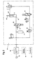
- the piston-cylinder drive 6 is controlled by a pneumatic control system 19th driven, which is shown in Figs. 2 and 3 in more detail. As shown in FIG. 2, is the working port 6.1 of the piston-cylinder drive 6 via a quick-opening, electromagnetically actuated control valve 10 on the one hand with an outlet and on the other hand with a pressure reduction unit 20, the will be described in more detail below, and a compressed air reservoir 11 connectable.
- the pressure reducing unit 20 is in the usual way to a compressed air source 14 connected.
- the return port 6.2 of the piston-cylinder drive 6 is a quick exhaust valve 12 on the one hand to a Outlet and on the other hand via a second electromagnetically controllable Control valve 13, with the interposition of a pressure limiter 16, on the one hand connectable to the compressed air reservoir 11 and on the other hand to an outlet. Due to the short switching time of the control valve 10 is achieved that the required volume flow quickly at the piston-cylinder drive 6 available stands.
- the acceleration is initiated, there is a sudden pressure available, through which the piston is guided to the front and the carriage accelerated. This is the one located on the other side of the piston Air column during the acceleration stroke via the quick exhaust valve 12th pushed out. At the end of the acceleration stroke, the carriage 4 is decelerated and the carriage returned to the starting position.
- the pressure reduction unit 20 which, as shown in FIG. 3, a Proportional pressure control valve 20.1, which has an electrical control unit 18 is controlled.
- the electric control unit 18 are the determined for the respective elevation of the gun barrel 1 control signals from the fire control system 17 or another position transmitter, e.g. the Encoder 17.1 supplied to the gun. This ensures that at decreasing elevation of the piecing pressure is reduced, according to regularities as explained at the beginning and below of Fig. 4 are illustrated again.
- the input pressure P 1 of the pressure reducing unit 20 is the pressure supplied by the pressure source 14, while the output pressure P 2 corresponds to the reduced pressure in dependence on the elevation angle.
- the proportional pressure control valve 20.1 is connected in parallel with a manually actuatable pressure reducing valve 20.3.
- the proportional pressure control valve 20.1 and the pressure reducing valve 20.3 are selectively connected via an electromagnetic switching valve 20.2 with the quick-opening control valve 10, wherein the circuit is such that the electromagnetic switching valve 20.2 in the de-energized state, ie in an emergency, the manually operable pressure reducing valve 20.3 with the quick-opening control valve 10 leading line connects.
- FIG. 4 shows the dependency of the attachment speed V Ans on the elevation angle El in graphic representations.
- the dashed curve ST shows the dependence of the attachment speed from the elevation angle in a conventional Geschoßansetzer after the state the technique in which over the entire elevation range with the same Starting pressure is worked.
- Curves I and II define upper and lower limits for the range of attachment speeds allowed at certain elevation angles.
Landscapes
- Engineering & Computer Science (AREA)
- General Engineering & Computer Science (AREA)
- Aiming, Guidance, Guns With A Light Source, Armor, Camouflage, And Targets (AREA)
- Laminated Bodies (AREA)
- Toys (AREA)
- Fluid-Pressure Circuits (AREA)
- Manipulator (AREA)
- Mechanically-Actuated Valves (AREA)
- Servomotors (AREA)
- Medicines Containing Antibodies Or Antigens For Use As Internal Diagnostic Agents (AREA)
- Glass Compositions (AREA)
- Superconductors And Manufacturing Methods Therefor (AREA)
Description
Claims (3)
- Geschoßansetzer für ein Artilleriegeschütz, das ein in Elevation schwenkbares Rohr aufweist, mit einem hinter dem Waffenrohr angeordneten Schlitten, der eine fluchtend zum Ladungsraum angeordnete Aufnahmevorrichtung mit einem Angriffselement am hinteren Ende für das Geschoß trägt und über eine Führung bewegbar auf einer parallel zur Waffenrohrachse verlaufenden Führungsbahn geführt ist und der mit einem pneumatischen Kolben-Zylinderantrieb zur Beschleunigung in Richtung auf das Waffenrohr gekoppelt ist und eine Bremsvorrichtung zur Abbremsung in einem vorgegebenen Abstand vor dem Waffenrohrende aufweist, wobei der Antrieb des Kolben-Zylinderantriebs über ein pneumatisches Steuersystem erfolgt mit einem schnellöffnenden Steuerventil, über welches der Arbeitsanschluß des Kolben-Zylinderantriebs wahlweise an eine Druckluftquelle oder einen Auslaß anschließbar ist, dadurch gekennzeichnet, daß zwischen der Druckluftquelle (14) und dem schnellöffnenden Steuerventil (10) eine Druckreduziereinheit (20) angeordnet ist mit einem von einer elektrischen Steuereinheit (18) angesteuerten Proportional-Druckregelventil (20.1), wobei der elektrischen Steuereinheit (18) Signale zugeführt werden, die von der Feuerleitanlage (17) oder einem Stellungsgeber (17.1) bereitgestellt werden, und die Ansteuerung des Proportional-Druckregel ventils (20.1) derart ist, daß bei abnehmender Elevation der Ansetzdruck gemäß einer Gesetzmäßigkeit derart reduziert wird, daß die Ansetzgeschwindigkeit (VAns) in Abhängigkeit von der Elevation (El) folgender Beziehung genügt
- Geschoßansetzer nach Anspruch 1, dadurch gekennzeichnet, daß dem Proportional-Druckregelventil (20.1) ein manuell betätigbares Druckreduzierventil (20.3) parallel geschaltet ist, welches bei Stromausfall im Notbetrieb an Stelle des Proportional-Druckregelventils (20.1) zwischen die Druckluftquelle (14) und dem schnellöffnenden Steuerventil (10) einschaltbar ist.
- Geschoßansetzer nach Anspruch 2, dadurch gekennzeichnet, daß das Proportional-Druckregelventil (20.1) und das Druckreduzierventil (20.3) wahlweise über ein elektromagnetisches Umschaltventil (20.2) mit dem schnellöffnenden Steuerventil (10) verbindbar sind, wobei das elektromagnetische Umschaltventil (20.2) im stromlosen Zustand auf das Druckreduzierventil (20.3) schaltet.
Applications Claiming Priority (2)
| Application Number | Priority Date | Filing Date | Title |
|---|---|---|---|
| DE19914663A DE19914663A1 (de) | 1999-03-31 | 1999-03-31 | Geschoßansetzer für ein Artilleriegeschütz |
| DE19914663 | 1999-03-31 |
Publications (3)
| Publication Number | Publication Date |
|---|---|
| EP1041355A2 EP1041355A2 (de) | 2000-10-04 |
| EP1041355A3 EP1041355A3 (de) | 2002-01-16 |
| EP1041355B1 true EP1041355B1 (de) | 2005-05-11 |
Family
ID=7903116
Family Applications (1)
| Application Number | Title | Priority Date | Filing Date |
|---|---|---|---|
| EP00104243A Expired - Lifetime EP1041355B1 (de) | 1999-03-31 | 2000-03-02 | Geschossansetzer für ein Artilleriegeschütz |
Country Status (6)
| Country | Link |
|---|---|
| US (1) | US6443045B1 (de) |
| EP (1) | EP1041355B1 (de) |
| AT (1) | ATE295525T1 (de) |
| DE (2) | DE19914663A1 (de) |
| ES (1) | ES2241516T3 (de) |
| NO (1) | NO317815B1 (de) |
Cited By (1)
| Publication number | Priority date | Publication date | Assignee | Title |
|---|---|---|---|---|
| WO2018184632A1 (de) | 2017-04-06 | 2018-10-11 | Krauss-Maffei Wegmann Gmbh & Co. Kg | Vorrichtung zum laden einer rohrwaffe mit munitionskörpern |
Families Citing this family (1)
| Publication number | Priority date | Publication date | Assignee | Title |
|---|---|---|---|---|
| SE513006C2 (sv) * | 1999-01-20 | 2000-06-19 | Bofors Weapon Sys Ab | Sätt och anordning för att hantera artillerigranater vid laddning av artilleripjäser |
Family Cites Families (4)
| Publication number | Priority date | Publication date | Assignee | Title |
|---|---|---|---|---|
| US3884119A (en) * | 1955-05-02 | 1975-05-20 | Aai Corp | Loading device for guns |
| CH662175A5 (en) * | 1984-11-15 | 1987-09-15 | Sig Schweiz Industrieges | Acceleration device for a loading device of a gun |
| CH664627A5 (de) * | 1986-11-20 | 1988-03-15 | Sig Schweiz Industrieges | Beschleunigungseinrichtung fuer eine ladevorrichtung eines geschuetzes. |
| DE3825662A1 (de) * | 1988-07-28 | 1990-02-08 | Wegmann & Co | Geschossansetzer fuer artillerie |
-
1999
- 1999-03-31 DE DE19914663A patent/DE19914663A1/de not_active Withdrawn
-
2000
- 2000-03-02 DE DE50010257T patent/DE50010257D1/de not_active Expired - Lifetime
- 2000-03-02 ES ES00104243T patent/ES2241516T3/es not_active Expired - Lifetime
- 2000-03-02 AT AT00104243T patent/ATE295525T1/de active
- 2000-03-02 EP EP00104243A patent/EP1041355B1/de not_active Expired - Lifetime
- 2000-03-23 US US09/533,129 patent/US6443045B1/en not_active Expired - Fee Related
- 2000-03-30 NO NO20001657A patent/NO317815B1/no not_active IP Right Cessation
Cited By (4)
| Publication number | Priority date | Publication date | Assignee | Title |
|---|---|---|---|---|
| WO2018184632A1 (de) | 2017-04-06 | 2018-10-11 | Krauss-Maffei Wegmann Gmbh & Co. Kg | Vorrichtung zum laden einer rohrwaffe mit munitionskörpern |
| DE102017107442A1 (de) | 2017-04-06 | 2018-10-11 | Krauss-Maffei Wegmann Gmbh & Co. Kg | Vorrichtung zum Laden einer Rohrwaffe mit Munitionskörpern |
| DE102017107442B4 (de) * | 2017-04-06 | 2021-03-18 | Krauss-Maffei Wegmann Gmbh & Co. Kg | Vorrichtung zum Laden einer Rohrwaffe mit Munitionskörpern |
| US11015888B2 (en) | 2017-04-06 | 2021-05-25 | Krauss-Maffei Wegmann Gmbh & Co. Kg | Device for loading a barreled weapon with ammunition bodies |
Also Published As
| Publication number | Publication date |
|---|---|
| EP1041355A2 (de) | 2000-10-04 |
| ES2241516T3 (es) | 2005-11-01 |
| ATE295525T1 (de) | 2005-05-15 |
| NO20001657D0 (no) | 2000-03-30 |
| NO317815B1 (no) | 2004-12-13 |
| NO20001657L (no) | 2000-10-02 |
| EP1041355A3 (de) | 2002-01-16 |
| US6443045B1 (en) | 2002-09-03 |
| DE50010257D1 (de) | 2005-06-16 |
| DE19914663A1 (de) | 2000-10-05 |
Similar Documents
| Publication | Publication Date | Title |
|---|---|---|
| EP0477510B1 (de) | Steuer- und Regelvorrichtung für ein hydrostatisches Getriebe | |
| DE3728533C2 (de) | ||
| EP0849468A2 (de) | Verstelleinrichtung zur Verstellung des Fördervolumens einer Axialkolbenpumpe | |
| EP3189296B1 (de) | Ausstossrohr für unterseeboot | |
| EP0352584B1 (de) | Geschossansetzer für Artillerie | |
| DE4319280C1 (de) | Hydrostatischer Fahrantrieb | |
| DE2424973B2 (de) | Einrichtung zum Steuern von Hydroantrieben | |
| DE2541398A1 (de) | Regeleinrichtung fuer einen hydrostatischen fahrantrieb, insbesondere fuer gabelstapler | |
| DE3619331C2 (de) | ||
| EP0163626A1 (de) | Geschütz | |
| EP1041355A2 (de) | Geschossansetzer für ein Artilleriegeschütz | |
| DE10138026A1 (de) | Verfahren zum Steuern des Bewegungsablaufs von Pneumatikantrieben, sowie Pneumatikantriebssteuerung | |
| DE3733215A1 (de) | Vorrichtung und verfahren zum laengsaxialen bewegen eines waffenrohres | |
| CH662175A5 (en) | Acceleration device for a loading device of a gun | |
| DE2532768B2 (de) | Hydraulische Servomotoranlage | |
| DE1022101B (de) | Hydraulische Antriebsuebertragung, insbesondere fuer Kraftfahrzeuge | |
| DE2900320C2 (de) | Automatisch wirkende hydraulische Sicherheitseinrichtung für schwenkbare Mähbalken o.dgl. | |
| DE2206788A1 (de) | Verstellbare hydropumpe mit druckregelung | |
| DE2337481C2 (de) | Folgesteuereinrichtung für eine verstellbare Pumpe | |
| EP0053370A2 (de) | Verfahren zur Steuerung eines hydraulischen Antriebs und für die Durchführung dieses Steuerungsverfahrens geeigneter hydraulischer Antrieb | |
| DE1943455C3 (de) | Einrichtung zum selbsttätigen Umschalten von Eilvorschub auf Arbeitsvorschub bei einer druckluftbetriebenen Bohrvorschubeinheit | |
| DE2316317A1 (de) | Druckluftschusswaffe | |
| EP0627608B1 (de) | Automatischer Ansetzer für Artilleriegeschosse | |
| DE2614104C2 (de) | Verfahren und Vorrichtung zum Aufbringen des Nachdrucks bei einer Kaltkammer-Druckgießmaschine | |
| DE3333990A1 (de) | Motorgreifer-antrieb |
Legal Events
| Date | Code | Title | Description |
|---|---|---|---|
| PUAI | Public reference made under article 153(3) epc to a published international application that has entered the european phase |
Free format text: ORIGINAL CODE: 0009012 |
|
| AK | Designated contracting states |
Kind code of ref document: A2 Designated state(s): AT BE CH CY DE DK ES FI FR GB GR IE IT LI LU MC NL PT SE |
|
| AX | Request for extension of the european patent |
Free format text: AL;LT;LV;MK;RO;SI |
|
| PUAL | Search report despatched |
Free format text: ORIGINAL CODE: 0009013 |
|
| AK | Designated contracting states |
Kind code of ref document: A3 Designated state(s): AT BE CH CY DE DK ES FI FR GB GR IE IT LI LU MC NL PT SE |
|
| AX | Request for extension of the european patent |
Free format text: AL;LT;LV;MK;RO;SI |
|
| 17P | Request for examination filed |
Effective date: 20011217 |
|
| AKX | Designation fees paid |
Free format text: AT BE CH CY DE DK ES FI FR GB GR IE IT LI LU MC NL PT SE |
|
| 17Q | First examination report despatched |
Effective date: 20040204 |
|
| GRAP | Despatch of communication of intention to grant a patent |
Free format text: ORIGINAL CODE: EPIDOSNIGR1 |
|
| GRAS | Grant fee paid |
Free format text: ORIGINAL CODE: EPIDOSNIGR3 |
|
| GRAA | (expected) grant |
Free format text: ORIGINAL CODE: 0009210 |
|
| AK | Designated contracting states |
Kind code of ref document: B1 Designated state(s): AT BE CH CY DE DK ES FI FR GB GR IE IT LI LU MC NL PT SE |
|
| PG25 | Lapsed in a contracting state [announced via postgrant information from national office to epo] |
Ref country code: IE Free format text: LAPSE BECAUSE OF FAILURE TO SUBMIT A TRANSLATION OF THE DESCRIPTION OR TO PAY THE FEE WITHIN THE PRESCRIBED TIME-LIMIT Effective date: 20050511 Ref country code: FI Free format text: LAPSE BECAUSE OF FAILURE TO SUBMIT A TRANSLATION OF THE DESCRIPTION OR TO PAY THE FEE WITHIN THE PRESCRIBED TIME-LIMIT Effective date: 20050511 |
|
| REG | Reference to a national code |
Ref country code: GB Ref legal event code: FG4D Free format text: NOT ENGLISH |
|
| REG | Reference to a national code |
Ref country code: CH Ref legal event code: EP |
|
| REG | Reference to a national code |
Ref country code: IE Ref legal event code: FG4D Free format text: LANGUAGE OF EP DOCUMENT: GERMAN |
|
| REF | Corresponds to: |
Ref document number: 50010257 Country of ref document: DE Date of ref document: 20050616 Kind code of ref document: P |
|
| REG | Reference to a national code |
Ref country code: CH Ref legal event code: NV Representative=s name: A. BRAUN, BRAUN, HERITIER, ESCHMANN AG PATENTANWAE |
|
| GBT | Gb: translation of ep patent filed (gb section 77(6)(a)/1977) |
Effective date: 20050622 |
|
| REG | Reference to a national code |
Ref country code: SE Ref legal event code: TRGR |
|
| PG25 | Lapsed in a contracting state [announced via postgrant information from national office to epo] |
Ref country code: DK Free format text: LAPSE BECAUSE OF FAILURE TO SUBMIT A TRANSLATION OF THE DESCRIPTION OR TO PAY THE FEE WITHIN THE PRESCRIBED TIME-LIMIT Effective date: 20050811 |
|
| REG | Reference to a national code |
Ref country code: GR Ref legal event code: EP Ref document number: 20050402094 Country of ref document: GR |
|
| PG25 | Lapsed in a contracting state [announced via postgrant information from national office to epo] |
Ref country code: PT Free format text: LAPSE BECAUSE OF FAILURE TO SUBMIT A TRANSLATION OF THE DESCRIPTION OR TO PAY THE FEE WITHIN THE PRESCRIBED TIME-LIMIT Effective date: 20051019 |
|
| REG | Reference to a national code |
Ref country code: ES Ref legal event code: FG2A Ref document number: 2241516 Country of ref document: ES Kind code of ref document: T3 |
|
| REG | Reference to a national code |
Ref country code: IE Ref legal event code: FD4D |
|
| PLBE | No opposition filed within time limit |
Free format text: ORIGINAL CODE: 0009261 |
|
| STAA | Information on the status of an ep patent application or granted ep patent |
Free format text: STATUS: NO OPPOSITION FILED WITHIN TIME LIMIT |
|
| PG25 | Lapsed in a contracting state [announced via postgrant information from national office to epo] |
Ref country code: BE Free format text: LAPSE BECAUSE OF NON-PAYMENT OF DUE FEES Effective date: 20060331 Ref country code: LU Free format text: LAPSE BECAUSE OF NON-PAYMENT OF DUE FEES Effective date: 20060331 Ref country code: MC Free format text: LAPSE BECAUSE OF NON-PAYMENT OF DUE FEES Effective date: 20060331 |
|
| ET | Fr: translation filed | ||
| 26N | No opposition filed |
Effective date: 20060214 |
|
| BERE | Be: lapsed |
Owner name: KRAUSS-MAFFEI WEGMANN G.M.B.H. & CO. KG Effective date: 20060331 |
|
| REG | Reference to a national code |
Ref country code: CH Ref legal event code: PFA Owner name: KRAUSS-MAFFEI WEGMANN GMBH & CO. KG Free format text: KRAUSS-MAFFEI WEGMANN GMBH & CO. KG#AUGUST-BODE-STRASSE 1#34127 KASSEL (DE) -TRANSFER TO- KRAUSS-MAFFEI WEGMANN GMBH & CO. KG#AUGUST-BODE-STRASSE 1#34127 KASSEL (DE) |
|
| PG25 | Lapsed in a contracting state [announced via postgrant information from national office to epo] |
Ref country code: CY Free format text: LAPSE BECAUSE OF FAILURE TO SUBMIT A TRANSLATION OF THE DESCRIPTION OR TO PAY THE FEE WITHIN THE PRESCRIBED TIME-LIMIT Effective date: 20050511 |
|
| PGFP | Annual fee paid to national office [announced via postgrant information from national office to epo] |
Ref country code: NL Payment date: 20130318 Year of fee payment: 14 Ref country code: GR Payment date: 20130319 Year of fee payment: 14 |
|
| PGFP | Annual fee paid to national office [announced via postgrant information from national office to epo] |
Ref country code: AT Payment date: 20130318 Year of fee payment: 14 |
|
| REG | Reference to a national code |
Ref country code: CH Ref legal event code: PCAR Free format text: NEW ADDRESS: HOLBEINSTRASSE 36-38, 4051 BASEL (CH) |
|
| REG | Reference to a national code |
Ref country code: NL Ref legal event code: V1 Effective date: 20141001 |
|
| REG | Reference to a national code |
Ref country code: AT Ref legal event code: MM01 Ref document number: 295525 Country of ref document: AT Kind code of ref document: T Effective date: 20140302 |
|
| REG | Reference to a national code |
Ref country code: GR Ref legal event code: ML Ref document number: 20050402094 Country of ref document: GR Effective date: 20141002 |
|
| PG25 | Lapsed in a contracting state [announced via postgrant information from national office to epo] |
Ref country code: GR Free format text: LAPSE BECAUSE OF NON-PAYMENT OF DUE FEES Effective date: 20141002 |
|
| PG25 | Lapsed in a contracting state [announced via postgrant information from national office to epo] |
Ref country code: NL Free format text: LAPSE BECAUSE OF NON-PAYMENT OF DUE FEES Effective date: 20141001 Ref country code: AT Free format text: LAPSE BECAUSE OF NON-PAYMENT OF DUE FEES Effective date: 20140302 |
|
| REG | Reference to a national code |
Ref country code: FR Ref legal event code: PLFP Year of fee payment: 17 |
|
| REG | Reference to a national code |
Ref country code: FR Ref legal event code: PLFP Year of fee payment: 18 |
|
| REG | Reference to a national code |
Ref country code: FR Ref legal event code: PLFP Year of fee payment: 19 |
|
| PGFP | Annual fee paid to national office [announced via postgrant information from national office to epo] |
Ref country code: CH Payment date: 20180326 Year of fee payment: 19 Ref country code: GB Payment date: 20180326 Year of fee payment: 19 |
|
| PGFP | Annual fee paid to national office [announced via postgrant information from national office to epo] |
Ref country code: FR Payment date: 20180326 Year of fee payment: 19 Ref country code: IT Payment date: 20180322 Year of fee payment: 19 Ref country code: SE Payment date: 20180326 Year of fee payment: 19 |
|
| PGFP | Annual fee paid to national office [announced via postgrant information from national office to epo] |
Ref country code: ES Payment date: 20180423 Year of fee payment: 19 Ref country code: DE Payment date: 20180331 Year of fee payment: 19 |
|
| REG | Reference to a national code |
Ref country code: DE Ref legal event code: R119 Ref document number: 50010257 Country of ref document: DE |
|
| REG | Reference to a national code |
Ref country code: SE Ref legal event code: EUG |
|
| PG25 | Lapsed in a contracting state [announced via postgrant information from national office to epo] |
Ref country code: SE Free format text: LAPSE BECAUSE OF NON-PAYMENT OF DUE FEES Effective date: 20190303 |
|
| REG | Reference to a national code |
Ref country code: CH Ref legal event code: PL |
|
| GBPC | Gb: european patent ceased through non-payment of renewal fee |
Effective date: 20190302 |
|
| PG25 | Lapsed in a contracting state [announced via postgrant information from national office to epo] |
Ref country code: GB Free format text: LAPSE BECAUSE OF NON-PAYMENT OF DUE FEES Effective date: 20190302 Ref country code: DE Free format text: LAPSE BECAUSE OF NON-PAYMENT OF DUE FEES Effective date: 20191001 Ref country code: CH Free format text: LAPSE BECAUSE OF NON-PAYMENT OF DUE FEES Effective date: 20190331 Ref country code: LI Free format text: LAPSE BECAUSE OF NON-PAYMENT OF DUE FEES Effective date: 20190331 |
|
| PG25 | Lapsed in a contracting state [announced via postgrant information from national office to epo] |
Ref country code: IT Free format text: LAPSE BECAUSE OF NON-PAYMENT OF DUE FEES Effective date: 20190302 Ref country code: FR Free format text: LAPSE BECAUSE OF NON-PAYMENT OF DUE FEES Effective date: 20190331 |
|
| REG | Reference to a national code |
Ref country code: ES Ref legal event code: FD2A Effective date: 20200724 |
|
| PG25 | Lapsed in a contracting state [announced via postgrant information from national office to epo] |
Ref country code: ES Free format text: LAPSE BECAUSE OF NON-PAYMENT OF DUE FEES Effective date: 20190303 |