EP1040333B1 - Membrane pour cellule de mesure sous vide a capacite - Google Patents
Membrane pour cellule de mesure sous vide a capacite Download PDFInfo
- Publication number
- EP1040333B1 EP1040333B1 EP98956751A EP98956751A EP1040333B1 EP 1040333 B1 EP1040333 B1 EP 1040333B1 EP 98956751 A EP98956751 A EP 98956751A EP 98956751 A EP98956751 A EP 98956751A EP 1040333 B1 EP1040333 B1 EP 1040333B1
- Authority
- EP
- European Patent Office
- Prior art keywords
- membrane
- accordance
- temperature
- smoothing
- heating stage
- Prior art date
- Legal status (The legal status is an assumption and is not a legal conclusion. Google has not performed a legal analysis and makes no representation as to the accuracy of the status listed.)
- Expired - Lifetime
Links
Images
Classifications
-
- G—PHYSICS
- G01—MEASURING; TESTING
- G01L—MEASURING FORCE, STRESS, TORQUE, WORK, MECHANICAL POWER, MECHANICAL EFFICIENCY, OR FLUID PRESSURE
- G01L9/00—Measuring steady of quasi-steady pressure of fluid or fluent solid material by electric or magnetic pressure-sensitive elements; Transmitting or indicating the displacement of mechanical pressure-sensitive elements, used to measure the steady or quasi-steady pressure of a fluid or fluent solid material, by electric or magnetic means
- G01L9/0041—Transmitting or indicating the displacement of flexible diaphragms
- G01L9/0072—Transmitting or indicating the displacement of flexible diaphragms using variations in capacitance
- G01L9/0075—Transmitting or indicating the displacement of flexible diaphragms using variations in capacitance using a ceramic diaphragm, e.g. alumina, fused quartz, glass
-
- G—PHYSICS
- G01—MEASURING; TESTING
- G01L—MEASURING FORCE, STRESS, TORQUE, WORK, MECHANICAL POWER, MECHANICAL EFFICIENCY, OR FLUID PRESSURE
- G01L9/00—Measuring steady of quasi-steady pressure of fluid or fluent solid material by electric or magnetic pressure-sensitive elements; Transmitting or indicating the displacement of mechanical pressure-sensitive elements, used to measure the steady or quasi-steady pressure of a fluid or fluent solid material, by electric or magnetic means
- G01L9/0041—Transmitting or indicating the displacement of flexible diaphragms
- G01L9/0042—Constructional details associated with semiconductive diaphragm sensors, e.g. etching, or constructional details of non-semiconductive diaphragms
- G01L9/0044—Constructional details of non-semiconductive diaphragms
Definitions
- the invention relates to a membrane for a capacitive Vacuum measuring cell according to the preamble of patent claim 1.
- a known and suitable method for measuring the deflection of such membranes is that the membrane arrangement is designed as a variable electrical capacitance, the capacitance change, which correlates with the pressure change, being evaluated in a known manner via measuring electronics.
- the capacitance is formed in that the thin, flexible membrane surface is arranged at a short distance from another surface and both opposite surfaces are coated with an electrically conductive covering or are made of electrically conductive material.
- the deflection changes the distance between the two electrodes, which leads to an evaluable change in the capacitance of the arrangement.
- Large numbers of sensors of this type are made of silicon.
- Both the flat base body and the membrane often consist entirely of silicon material.
- a combined material composition e.g. silicon with a glass base.
- This enables the sensors to be manufactured inexpensively.
- pressure sensors of this type can generally only be used for higher pressure ranges in the range from approx. 10 -1 mbar to a few bar.
- High resolution at lower pressures from around 10 -1 mbar can no longer be achieved with silicon.
- this stems from the fact that the surface of the silicon reacts with the environment, thus disrupting the sensitive sensor characteristics. Even water vapor, which is contained in normal atmospheric air, leads to corresponding reactions on the surfaces. The problem is further exacerbated when the sensor is used in chemically aggressive atmospheres.
- FIG. 1 A known arrangement of this type is shown in Fig. 1.
- the measuring cell consists of a ceramic plate (20), over the surface of which a membrane (22) is arranged at a short distance, which is connected to the ceramic plate (20) in the edge area with a sealing seal (21).
- the ceramic plate (20) thus forms, together with the membrane (22), a reference vacuum space (25), which was evacuated via a pump opening during manufacture and is sealed with a seal (28).
- the surfaces of the ceramic plate (20) and the membrane (22) lying opposite one another in the reference vacuum space (25) are coated in an electrically conductive manner and are led outwards with insulated connections in order to evaluate the capacitance signal with electronics (not shown in the figure).
- the plate (20) and the membrane (22) are both made of ceramic material, such as Al 2 O 3 , in order to achieve corrosion resistance.
- This measuring cell is in turn arranged in a vacuum-tight housing (23) which is provided with a measuring cell connection (24) which is connected to the media to be measured.
- the measuring vacuum space (26) that forms is connected via the measuring cell connection (24) to the membrane (22) with an elastomer seal (27) so that the pressures to be measured only act on the membrane surface (22).
- measuring cells of this type can only be used for higher pressures in the range from 0.1 mbar to 100 bar.
- This design also leads to tension in the materials, which significantly impairs the reproducibility of the measurement results and the resolution in the low pressure range, for example ⁇ 1 mbar.
- the ceramic membranes (22) used up to now have a thickness in the range from 279 ⁇ m to 2540 ⁇ m.
- Such constructions do not make it possible to realize large measuring ranges, in particular down to low pressures of 0.1 mbar to 10 -6 mbar, and constructions of this type, as are also disclosed in US Pat. No. 5,553,502, are costly.
- the present invention has set itself the task of eliminating the disadvantages of the prior art.
- the object of the present invention is to implement a membrane made of Al 2 O 3 that is simple and inexpensive to produce for a vacuum measuring cell, which allows pressures in the range from 10 -6 mbar to 1000 mbar, in particular from 10 -6 mbar to 1 mbar with an accuracy of better than 1%, preferably better than 0.3% of the measured value.
- the measuring range can be covered by several cell or membrane designs according to the invention.
- the membrane should be corrosion-resistant against aggressive media.
- the membrane according to the invention is made entirely of a ceramic, such as in particular Al 2 O 3 . This ensures very high corrosion resistance and long-lasting reproducibility.
- a measuring cell assembly can thus be made entirely of corrosion-resistant materials, in particular ceramic. Only in areas where sealing has to be carried out or where bushings are provided are materials other than Al 2 O 3 provided in small quantities, unless the Al 2 O 3 is welded without the addition of foreign material.
- a cell consists of a first plate-shaped housing body, over which a membrane is sealingly arranged in the edge area, so that it encloses a reference vacuum space. On the side facing away from the reference vacuum space, a second housing body is also sealingly spaced in the edge region, so that a measurement vacuum space is formed there.
- This measuring vacuum chamber is provided with a connection for the supply of the medium to be measured.
- the surfaces of the first housing body and the membrane, which form the reference vacuum space, are coated in an electrically conductive manner, for example with gold, and form the electrodes of the capacitance measuring cell.
- the electrodes in turn are led out, for example through the first housing body or through the sealing area in the edge zone.
- the electrode surfaces, which are arranged essentially in parallel, are at a distance in the range from 2 ⁇ m to 50 ⁇ m.
- the membrane in the edge region is preferably sealed off from the two housings by welding, for example by laser welding.
- a glass solder which is also corrosion-resistant, is also very suitable and easy to use.
- Another possibility of the sealing connection is to connect housing parts diffusively, for example in the green body stage, when it is a matter of completely avoiding material foreign to Al 2 O 3 .
- Such thin membranes are particularly difficult to manufacture and need at least one more after the sintering step Smoothing step. It is also particularly important that the Membrane has sufficient helium tightness, which only achieves can be if the grain sizes of the membrane material do not increase are large and are in the range of ⁇ 20 ⁇ m. smaller Grain sizes of ⁇ 10 ⁇ m are preferred, especially those which are ⁇ 5 ⁇ m. In any case, the cross section of the membrane Considered at least two grains across the thickness If there are more than five grains one above the other, the membranes are particularly dense.
- the bump in any case should not cover the entire area Be more than 30% of the electrode gap, being better is if it is not more than 15%. This means that the unevenness over the entire area is not larger than 10 ⁇ m should be, preferably not more than 5 ⁇ m.
- the bump is defined as the difference from the lowest to the highest Point.
- the purity of the aluminum oxide used In order to achieve good long-term stability, the membrane should be at least 94%, with preferred values above 99% lie.
- the reference vacuum space must have a long-term stable vacuum Have quality to ensure the precise function of the measuring cell to be able to guarantee for a long time. This is after pumping out to provide a getter, which is preferably in a small Volume is arranged on the first housing and in connection with the reference vacuum space. This getter ensures that the reference vacuum pressure is lower than the pressure to be measured, but preferably at least a decade lower. To impurities to avoid the inside of the measuring cell, a getter type should be chosen that is not vaporizing.
- Measuring cells with a membrane according to the invention can do a lot be built compactly and inexpensively.
- the diameter of one such cell can range from 5 to 80 mm, where preferably the measuring cell has a diameter of 5 to 40 mm.
- the thickness of such a cell is preferably in this case in the range from 2 mm to 25 mm.
- Membranes according to the invention made of Al 2 O 3 are produced by, as is customary in the field of ceramics, first mixing a slip according to a specific recipe and then applying the dough-like mass thinly and uniformly to a band-shaped carrier material, for example a plastic film. After drying, these foils are checked for defects, such as bubbles or holes.
- the mass now present, which has not yet been sintered and is therefore still flexible, is called the green body.
- the desired membrane shape, preferably circular, is now cut out of the ribbon-shaped green body material, this still adhering to the film. Cutting is carried out, for example, with knives, preferably with a laser.
- the green body must be cut out or scored with particular care, so that there are no distortions or raised portions against the surface of the future ceramic membrane on the cutting edge, which also determines the degree of waviness of the membrane. If the knife is used for cutting, a contact wheel can be carried out for this purpose at the same time as the cutting process, which prevents the green body from being thrown up too much.
- the membrane which is preferably cut out in a circular shape, is then carefully separated from the film, for example by pulling it off over an edge.
- the membranes are then sintered in an oven. For the sintering, the membranes are preferably placed on hard-fired, flat Al 2 O 3 plates and, for example, stacked at a distance from one another and sintered at typically 1630 ° C.
- the temperature is raised to this 1630 ° C for about 400 minutes, i.e. with a temperature rise of 4 ° C per minute, then left at this temperature for a few minutes, for example 6 minutes, and then in a first step with a slow temperature decrease of 3 ° C per minute Minute reduced to 1000 ° C for about 210 minutes and cooled again to ambient temperature in a further, second step with a temperature decrease of 6 ° C per minute for about 170 minutes.
- a ceramic membrane which has a hard, pure ceramic structure with respect to the green body, the additives of the green body material having evaporated. After this sintering step, the membrane is very uneven and has warpage of several millimeters with a diameter of about 40 mm.
- the membrane cannot be used in this condition due to the strong distortions and residual stresses in the material.
- the membrane must be smoothed with at least one further step. This is done by subjecting the membrane to a further heating step in the furnace.
- the membranes are carefully placed between solid and very flat hard sintered Al 2 O 3 plates (also "dead" -Al 2 O 3 , ie large-grained), which preferably have a weight of a few 10 to a few 100 grams with a membrane diameter of 40mm, as in the example, about 60 grams, or are weighted accordingly.
- the temperature is slowly ramped up to about 1570 ° C at 4 ° C per minute for about 390 minutes.
- the temperature is slowly lowered again, while about 115 minutes at about 5 ° C. per minute to 1000 ° C. have been reached. Thereafter, the temperature is further lowered at about 6 ° C per minute, for about 166 minutes until ambient temperature is reached.
- the membrane appears only with a very small warp of a few tenths of a millimeter. It is important in this smoothing step that the temperature is less high than the first sintering step, preferably up to a maximum of 100 ° C. below the sintering temperature. In order to achieve good results, which are necessary for the required measuring cell quality, this smoothing heating step must be carried out at least twice.
- the smoothing heating steps should be carried out in such a way that no more than two smoothing steps are necessary. Particularly good results are achieved in that the membrane is carefully detached from the plate between the smoothing heating steps and put down again in a somewhat offset position. It can even be stored upside down.
- the use of a stack of several flat plates with membranes in between makes the arrangement particularly economical.
- the quality of the membrane is crucial.
- the aforementioned Manufacturing process enables the production of thin Membranes of high density with very good flatness. Compliance corresponding parameters for sintering and the subsequent one Smoothing step are relevant here.
- sintering maximum temperatures must be reached from 1300 to 1800 ° C, preferably from 1400 to 1700 ° C. This temperature maximum should be achieved at least briefly, but a maximum of 180 minutes long in this area.
- the heating rate should be a maximum of 25 ° C per minute. Preferably the heating is divided into two steps. After reaching The further heating up to the final temperature should be between 1000 and 1300 ° C at a slower speed, with a maximum of 15 ° C per minute.
- the membrane After reaching or maintaining the aforementioned maximum temperature the membrane is cooled down again with a Maximum speed of 25 ° C per minute. To snap at one Heating and / or cooling the membranes become strong wavy and porous. Longer times don't hurt, but they are not economically.
- the smoothing temperature being the maximum never exceed the sintering temperature.
- the smoothing temperature is the maximum never exceed the sintering temperature.
- the smoothing temperature is the maximum never exceed the sintering temperature.
- the smoothing temperature is the maximum never exceed the sintering temperature.
- the smoothing temperature is the maximum never exceed the sintering temperature.
- the smoothing temperature is the maximum never exceed the sintering temperature.
- the smoothing temperature is the maximum never exceed the sintering temperature.
- membranes the optional thicknesses in the range from 10 ⁇ m to 250 ⁇ m, preferably ⁇ 120 ⁇ m.
- flatness of the membranes can be achieved that are better than 10 ⁇ m over the entire area are, preferably even better than 5 ⁇ m.
- the grains of the membrane material are on average smaller than 20 ⁇ m, preferably smaller than 10 ⁇ m, even those smaller than 5 ⁇ m are can be achieved.
- Helium-tight membranes can thus be realized which are necessary for the measuring cell requirement.
- the membrane is now ready for further use in the measuring cell assembly.
- the membrane and a flat surface of the first housing body made of Al 2 O 3 are now provided with an electrically conductive coating for the formation of the electrodes.
- an electrically conductive coating for the formation of the electrodes.
- a metal-containing for example a gold-containing paint can be used, which is, for example, brushed on, sprayed on or preferably printed on.
- Another method is to produce the electrically conductive layer using vacuum evaporation, preferably using sputtering.
- a gold layer which is first applied relatively thickly, approximately 1 ⁇ m, is then thinned again in the inner region, down to a few nanometers thick, approximately 5 nm an etching process, such as preferably an ion or sputter etching.
- an etching process such as preferably an ion or sputter etching.
- a practically easy to use and preferred method consists in first applying a thin layer of a few nm over the entire surface and then a thicker layer of gold with screen printing on the edge (ie using a combination method and different layer thicknesses).
- Membranes or housings treated in this way are then annealed at temperatures of a few 100 ° C., preferably in the range of 650 ° C.
- the second ceramic housing which is arranged on the measurement side, consists of a flat ceramic plate, which on the membrane side can have a flat recess to a sufficiently large To form the measurement vacuum space.
- the connecting piece is on this Ceramic housing by welding, gluing or soldering, preferably with a glass solder, connected so that the connection opening can communicate with the future vacuum room.
- the membrane is in the peripheral area where the seal takes place provided with glass paste on both sides, preferably with a screen printing process. After drying the membrane with the glass paste in an oven at some 100 ° C, preferably at about 670 ° C, baked. After that, the glass surface polished on both sides, preferably also the future one Electrode distance is defined.
- the upper ceramic housing on the electrode side can also be opened the outside with the help of the already mentioned coating process, be provided with an electrically conductive layer, to form a shield.
- the connection points attached to the housing here too the connection points attached to the housing.
- the holes for the electrical feedthrough metallized for the electrode connections preferably with Silver.
- the first housing with the electrode and the bushings, together with the membrane Tightness and checked for the electrode distance is put on and the entire structure is weight-loaded, to also test the function and the distances.
- the lower part of the housing is put on and the entire structure is weight-loaded, to also test the function and the distances.
- a mounting frame additionally putting on the getter connection and under weight load of about 200 grams burned in the glass seals at some 100 ° C, preferably at about 630 ° C, and then a test of whether the required distances have been maintained become. At most it can be caused by additional weight or relief and a further burning process of the membrane distance Getting corrected.
- the process of poetry must be very should be done carefully and, as already mentioned, at Measuring cell arrangement no voltages occur.
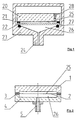
- FIG. 2 schematically and in cross section an inventive capacitive vacuum measuring cell.
- Fig. 3 is an enlarged view and a detail of the measuring cell according to FIG. 2.
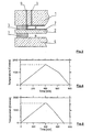
- Fig. 4 A temperature - time diagram for the sintering step Membrane.
- Fig. 5 A temperature-time diagram for a smoothing step the membrane.
- a capacitive measuring cell with a membrane according to the invention made of Al 2 O 3 with a structure essentially completely symmetrically arranged around the membrane is shown in cross section in FIG. 2.
- the first housing (1) consists of a ceramic plate made of Al 2 O 3 which is sealed at a distance of 2 ⁇ m to 50 ⁇ m relative to the ceramic membrane (2) in the edge area and includes a reference vacuum space (25).
- the distance between the two surfaces is usually set directly during assembly using the sealing material (3), which lies between the membrane edge and the housing edge. In this way, a completely flat housing plate (1) can be used.
- a measuring vacuum space (26) is formed in a second housing (4) on the opposite side of the membrane, which can be reached via a connecting piece (5) through an opening in the housing (4) for media to be measured.
- the seal (3) As mentioned, the distance on both sides of the membrane (2) defines the distance of the two housings (1 and 4).
- This seal is for example and preferably a glass solder, which is easy to handle and can be applied for example by screen printing.
- a typical measuring cell with an outer diameter of 38 mm and a free membrane inner diameter of 30 mm Distance (3) about 2 to 50 microns, preferably 12 to 35 microns.
- the first housing (1) is 5 mm thick
- the second housing (4) is preferred in the interior, as shown in Fig. 1, with an approx. 0.5 mm deep recess in order to close the measuring vacuum chamber (26) enlarge.
- the membrane (2) and the housing (1) are on the reference vacuum chamber side each with an electrically conductive layer (7) coated.
- the two layers are electrically connected to each other not connected.
- the layers (7) can, for example painted on, printed on, sprayed on or with a vacuum process be applied. They are preferably used with a Vacuum processes, such as applied by vapor deposition or sputtering.
- Gold which, for example, is particularly suitable as a layer material is evaporated with a layer thickness of 1 ⁇ m and afterwards using sputter etching to a few nanometers, for example 5 nm is thinned.
- the layer can thus be defined in thickness and thin enough to be tension-free.
- the electrical The membranes (7) are preferably connected with vacuum-tight, electrically conductive bushings (6), preferably through the housing (1), where it is then connected to the evaluation electronics can be connected.
- the drain pipe, which through the first housing plate (1) and the getter arrangement are not shown in Figure 3.
- FIG. 4 An example of an optimized time-temperature profile for the Sintering step of the membrane, starting from the green body, is in Figure 4 shown.
- sintering make sure that the membrane material has grain sizes after sintering, the are on average not larger than 20 ⁇ m, better not larger than 10 ⁇ m, preferably smaller than 5 ⁇ m, for high gas tightness or To ensure helium-tightness of the thin membrane.
- the thickness of the membrane should also be at least 2 grains, better 5 grains, should be present.
- the sintering step is the membrane by several mm compared to a plan Discarded area.
- the membrane is not yet usable and must be smoothed out that means that planities have to be achieved by the ideal flat area by no more than 10 ⁇ m, better by less than 5 ⁇ m. This is achieved by the Membrane, lying on a flat surface carefully up to your Softening is heated in an oven. She will then adapt to the flat surface with its own weight. To achieve better results, this process can be repeated and also the membrane between flat plates be pressed flat with slight pressure. It is particularly easy this when the diaphragm is loaded by its own weight the plates are made in the range of several 10 grams.
- the Membranes should be between the smoothing heating steps of the plan disassembled and twisted or put down again become. Two smoothing steps are usually sufficient and should be sought for economic reasons.
- FIG. 4 An example of an optimized time-temperature profile for one Smoothing step, starting from the one already sintered Membrane is shown in Figure 4.
- the membrane reaches a maximum temperature of 1570 ° C and remains below that the sintering temperature of 1630 ° C.
- the membrane will soft and can conform to the shaping, especially the plan Adjust the underlay using your own weight or weight.
Claims (17)
- Membrane pour cellule de mesure de vide en Al2O3, caractérisée en ce que la membrane (2) présente une épaisseur dans une gamme comprise entre 10 µm et 250 µm, et de préférence entre 10 µm et 120 µm, et en ce que la matière de la membrane comporte au moins 2 grains sur l'épaisseur en coupe transversale de la membrane (2).
- Membrane selon la revendication 1, caractérisée en ce que la granulométrie moyenne de la matière de la membrane est inférieure ou égale à 20 µm, de préférence inférieure ou égale à 10 µm et plus particulièrement à 5 µm.
- Membrane selon la revendication 1 ou 2, caractérisée en ce que l'on prévoit au moins 5 grains sur l'épaisseur en coupe transversale de la membrane (2).
- Membrane selon l'une quelconque des revendications précédentes, caractérisée en ce que les inégalités superficielles de la membrane (2) ne dépassent pas 10 µm, et de préférence 5 µm.
- Membrane selon l'une quelconque des revendications précédentes, caractérisée en ce que l'alumine Al2O3 de la membrane (2) présente une pureté d'au moins 94%, et de préférence d'au moins 99%.
- Membrane selon l'une quelconque des revendications précédentes, caractérisée par un diamètre compris entre 5 et 80 mm, et de préférence entre 5 et 40 mm, et en ce que la membrane est de préférence de forme circulaire.
- Membrane selon l'une quelconque des revendications précédentes, caractérisée en ce qu'au moins l'une de ses surfaces comporte un revêtement électriquement conducteur.
- Procédé de fabrication d'une membrane selon l'une quelconque des revendications 1 à 7, caractérisé en ce qu'il comporte les étapes suivantes :on met en forme des membranes à partir d'une barbotine de Al2O3 ;puis on réalise une première étape de chauffage pour le frittage de la membrane dans un four suivie d'un refroidissement ;et enfin, dans une deuxième étape de chauffage, on chauffe à nouveau la membrane pour assurer un lissage, puis on la refroidit.
- Procédé selon la revendication 8, caractérisé en ce que l'on réalise une troisième étape de chauffage de lissage.
- Procédé selon la revendication 8 ou 9, caractérisé en ce que la température de frittage de la première étape de chauffage entraíne un ramollissement de la membrane (2), la température de frittage n'étant pas dépassée.
- Procédé selon l'une quelconque des revendications 8 à 10, caractérisé en ce que la température de frittage de la première étape de chauffage est supérieure à la température de l'étape ou des étapes suivantes de chauffage de lissage, de préférence pas supérieure à 100°C.
- Procédé selon l'une quelconque des revendications 8 à 11, caractérisé en ce que, pendant la ou les étapes de chauffage de lissage, la membrane repose sur une plaque plane, de préférence entre des plaques planes, et, est, de préférence, lissée par compression, comme, en particulier par effet de masse.
- Procédé selon la revendication 12, caractérisé en ce que la membrane (2) est détachée des plaques entre deux étapes de chauffage de lissage et est redéposée en position décalée.
- Procédé selon la revendication 13, caractérisé en ce que, pour le lissage, on réalise un traitement thermique de plusieurs membranes (2) qui sont empilées les unes sur les autres entre des plaques planes.
- Procédé selon l'une quelconque des revendications 12 à 14, caractérisé en ce que la matière des plaques a, pour l'essentiel, le même coefficient de température que la matière de la membrane et est constituée, en particulier, de Al2O3, cette dernière étant, de préférence, frittée à froid et ayant une température de ramollissement plus grande que celle de la membrane.
- Procédé selon l'une quelconque des revendications 8 à 15, caractérisé en ce que la forme de la membrane est coulée ou comprimée à partir de la barbotine de Al2O3 et est, de préférence, découpée à partir d'un corps de base en Al2O3, sous forme de bande et déposé sur une feuille porteuse, et ôtée ensuite de la feuille.
- Utilisation de la membrane selon l'une quelconque des revendications précédentes dans une cellule de mesure sous vide à capacité, en particulier pour des pressions inférieures à 1000 mbar, et de préférence inférieures à 1 mbar, pour une résolution supérieure à 1%, de préférence supérieure à 0,3%.
Applications Claiming Priority (3)
| Application Number | Priority Date | Filing Date | Title |
|---|---|---|---|
| CH295497 | 1997-12-23 | ||
| CH295497 | 1997-12-23 | ||
| PCT/CH1998/000516 WO1999034185A1 (fr) | 1997-12-23 | 1998-12-04 | Membrane pour cellule de mesure sous vide a capacite |
Publications (2)
| Publication Number | Publication Date |
|---|---|
| EP1040333A1 EP1040333A1 (fr) | 2000-10-04 |
| EP1040333B1 true EP1040333B1 (fr) | 2002-07-03 |
Family
ID=4245386
Family Applications (1)
| Application Number | Title | Priority Date | Filing Date |
|---|---|---|---|
| EP98956751A Expired - Lifetime EP1040333B1 (fr) | 1997-12-23 | 1998-12-04 | Membrane pour cellule de mesure sous vide a capacite |
Country Status (6)
| Country | Link |
|---|---|
| US (2) | US6528008B1 (fr) |
| EP (1) | EP1040333B1 (fr) |
| JP (1) | JP4334139B2 (fr) |
| DE (1) | DE59804701D1 (fr) |
| HK (1) | HK1033690A1 (fr) |
| WO (1) | WO1999034185A1 (fr) |
Families Citing this family (27)
| Publication number | Priority date | Publication date | Assignee | Title |
|---|---|---|---|---|
| US20040099061A1 (en) * | 1997-12-22 | 2004-05-27 | Mks Instruments | Pressure sensor for detecting small pressure differences and low pressures |
| DE59804701D1 (de) * | 1997-12-23 | 2002-08-08 | Unaxis Balzers Ag | Membrane für eine kapazitive vakuummesszelle |
| EP1106982B1 (fr) | 1999-12-10 | 2005-02-09 | Endress + Hauser GmbH + Co. KG | Capteur de pression |
| DE10031135A1 (de) * | 2000-06-30 | 2002-01-17 | Grieshaber Vega Kg | Druckmeßvorrichtung |
| US6886410B1 (en) * | 2003-12-30 | 2005-05-03 | Honeywell International Inc. | Modified dual diaphragm pressure sensor |
| US6901807B1 (en) * | 2003-12-30 | 2005-06-07 | Honeywell International Inc. | Positive and negative pressure sensor |
| JP4678752B2 (ja) * | 2004-05-27 | 2011-04-27 | 東京エレクトロン株式会社 | 圧力計の製造方法及びガス処理装置の製造方法 |
| US7201057B2 (en) * | 2004-09-30 | 2007-04-10 | Mks Instruments, Inc. | High-temperature reduced size manometer |
| US7137301B2 (en) * | 2004-10-07 | 2006-11-21 | Mks Instruments, Inc. | Method and apparatus for forming a reference pressure within a chamber of a capacitance sensor |
| US7141447B2 (en) * | 2004-10-07 | 2006-11-28 | Mks Instruments, Inc. | Method of forming a seal between a housing and a diaphragm of a capacitance sensor |
| US7159467B2 (en) * | 2004-10-18 | 2007-01-09 | Silverbrook Research Pty Ltd | Pressure sensor with conductive ceramic membrane |
| JP5143736B2 (ja) * | 2005-08-12 | 2013-02-13 | インフィコン ゲゼルシャフト ミット ベシュレンクテル ハフツング | 測定セルおよびその製造方法 |
| JP4989659B2 (ja) * | 2006-01-18 | 2012-08-01 | インフィコン ゲゼルシャフト ミット ベシュレンクテル ハフツング | ダイヤフラムを備える真空測定セル |
| DE102006018049B4 (de) * | 2006-04-10 | 2008-10-16 | Fraunhofer-Gesellschaft zur Förderung der angewandten Forschung e.V. | Keramische Drucksensoren und Verfahren zu ihrer Herstellung |
| DE112007002372B4 (de) * | 2006-11-13 | 2017-04-06 | Inficon Gmbh | Vakuummembranmesszelle und Verfahren zur Herstellung einer derartigen Messzelle |
| CA2679648C (fr) * | 2007-04-07 | 2015-02-03 | Inficon Gmbh | Procede de production d'une cellule de mesure sous vide a membrane |
| US7946178B2 (en) * | 2007-06-19 | 2011-05-24 | Inficon Gmbh | Vacuum measuring cell device having a heater |
| DE112008003344A5 (de) * | 2007-12-20 | 2010-12-09 | Inficon Gmbh | Anordnung für eine Membrandruckmesszelle |
| DE102008064654A1 (de) * | 2008-08-05 | 2010-04-15 | Endress + Hauser Gmbh + Co. Kg | Verfahren zur Herstellung eines elastischen Körpers aus Al2O3- Keramik |
| US8485042B2 (en) * | 2008-08-05 | 2013-07-16 | Endress + Hauser Gmbh + Co. Kg | Method for manufacturing an elastic body of Al2O3 ceramic, measuring membrane for a pressure sensor and pressure sensor with such a membrane |
| US8552311B2 (en) * | 2010-07-15 | 2013-10-08 | Advanced Bionics | Electrical feedthrough assembly |
| DE102011004729A1 (de) * | 2011-02-25 | 2012-08-30 | Endress + Hauser Gmbh + Co. Kg | Keramische Druckmesszelle und Drucksensor mit keramischer Druckmesszelle |
| DE102011004722A1 (de) * | 2011-02-25 | 2012-08-30 | Endress + Hauser Gmbh + Co. Kg | Keramische Druckmesszelle |
| GB2493771B (en) | 2011-08-18 | 2017-05-31 | Oxsensis Ltd | Optical sensor |
| DE102011081887A1 (de) * | 2011-08-31 | 2013-02-28 | Robert Bosch Gmbh | Polymerschichtsystem-Drucksensorvorrichtung und Polymerschichtsystem-Drucksensorverfahren |
| US8640546B2 (en) * | 2011-09-12 | 2014-02-04 | Del Monte Corporation | Sensor for high pressure processing of articles |
| JP7444628B2 (ja) | 2020-02-19 | 2024-03-06 | アズビル株式会社 | 圧力センサ |
Family Cites Families (26)
| Publication number | Priority date | Publication date | Assignee | Title |
|---|---|---|---|---|
| US3619742A (en) | 1970-05-21 | 1971-11-09 | Rosemount Eng Co Ltd | Shielded capacitance pressure sensor |
| GB1353588A (en) | 1970-05-21 | 1974-05-22 | Lucas Industries Ltd | Spark igition systems |
| JPS54141587A (en) | 1978-04-26 | 1979-11-02 | Toshiba Corp | Production of semiconductor absolute pressure transducer |
| US4380041A (en) | 1978-09-25 | 1983-04-12 | Motorola Inc. | Capacitor pressure transducer with housing |
| EP0009313A1 (fr) * | 1978-09-25 | 1980-04-02 | Motorola, Inc. | Transducteur de pression et son assemblage |
| US4382247A (en) * | 1980-03-06 | 1983-05-03 | Robert Bosch Gmbh | Pressure sensor |
| US4329732A (en) | 1980-03-17 | 1982-05-11 | Kavlico Corporation | Precision capacitance transducer |
| US4340436A (en) * | 1980-07-14 | 1982-07-20 | International Business Machines Corporation | Process for flattening glass-ceramic substrates |
| DE3901492A1 (de) | 1988-07-22 | 1990-01-25 | Endress Hauser Gmbh Co | Drucksensor und verfahren zu seiner herstellung |
| US5026672A (en) * | 1990-06-25 | 1991-06-25 | Tektronix, Inc. | Method of fabricating a sintered body containing tin oxide |
| DE4031791A1 (de) | 1990-10-08 | 1992-04-09 | Leybold Ag | Sensor fuer ein kapazitaetsmanometer |
| US5315877A (en) | 1993-02-19 | 1994-05-31 | Kavlico Corporation | Low cost versatile pressure transducer |
| US5275054A (en) | 1993-04-07 | 1994-01-04 | Kavlico Corporation | Rubber free fluid pressure transducer |
| JP3280799B2 (ja) * | 1993-10-14 | 2002-05-13 | 日本碍子株式会社 | 薄肉ジルコニアダイヤフラム構造体及びその製造法並びにそれを用いた圧電/電歪膜型素子 |
| FR2714205A1 (fr) * | 1993-12-17 | 1995-06-23 | Atg Sa | Matériau composite pour l'enregistrement magnéto-optique, sa préparation et son utilisation. |
| US5436795A (en) * | 1994-03-28 | 1995-07-25 | Texas Instruments Incorporated | Pressure transducer apparatus and method for making same |
| SE506558C2 (sv) | 1994-04-14 | 1998-01-12 | Cecap Ab | Givarelement för tryckgivare |
| US5634999A (en) | 1994-09-06 | 1997-06-03 | Ngk Insulators, Ltd. | Method of producing ceramic diaphragm structure having convex diaphragm portion |
| JP3471447B2 (ja) | 1994-11-16 | 2003-12-02 | 日本碍子株式会社 | セラミックダイヤフラム構造体およびその製造方法 |
| US5553502A (en) | 1994-12-22 | 1996-09-10 | Kavlico Corporation | Capacitive pressure sensor with extruded indium vacuum seal |
| DE19509250C1 (de) | 1995-03-15 | 1996-09-12 | Bosch Gmbh Robert | Verfahren zur Herstellung eines Drucksensors |
| JP3429126B2 (ja) * | 1996-01-09 | 2003-07-22 | 日本碍子株式会社 | 微細貫通孔を有するセラミック部材の製造方法 |
| US5874162A (en) * | 1996-10-10 | 1999-02-23 | International Business Machines Corporation | Weighted sintering process and conformable load tile |
| US5932043A (en) * | 1997-03-18 | 1999-08-03 | International Business Machines Corporation | Method for flat firing aluminum nitride/tungsten electronic modules |
| DE59804701D1 (de) * | 1997-12-23 | 2002-08-08 | Unaxis Balzers Ag | Membrane für eine kapazitive vakuummesszelle |
| EP1070239B1 (fr) * | 1997-12-23 | 2002-04-24 | Unaxis Balzers Aktiengesellschaft | Cellule de mesure sous vide a capacite |
-
1998
- 1998-12-04 DE DE59804701T patent/DE59804701D1/de not_active Expired - Lifetime
- 1998-12-04 JP JP2000526789A patent/JP4334139B2/ja not_active Expired - Fee Related
- 1998-12-04 EP EP98956751A patent/EP1040333B1/fr not_active Expired - Lifetime
- 1998-12-04 WO PCT/CH1998/000516 patent/WO1999034185A1/fr active IP Right Grant
- 1998-12-22 US US09/218,934 patent/US6528008B1/en not_active Expired - Fee Related
-
2001
- 2001-03-28 HK HK01102263A patent/HK1033690A1/xx not_active IP Right Cessation
-
2003
- 2003-02-07 US US10/360,229 patent/US7107855B2/en not_active Expired - Fee Related
Also Published As
| Publication number | Publication date |
|---|---|
| US20030118802A1 (en) | 2003-06-26 |
| JP2002500352A (ja) | 2002-01-08 |
| US6528008B1 (en) | 2003-03-04 |
| DE59804701D1 (de) | 2002-08-08 |
| JP4334139B2 (ja) | 2009-09-30 |
| US7107855B2 (en) | 2006-09-19 |
| HK1033690A1 (en) | 2001-09-14 |
| EP1040333A1 (fr) | 2000-10-04 |
| WO1999034185A1 (fr) | 1999-07-08 |
Similar Documents
| Publication | Publication Date | Title |
|---|---|---|
| EP1040333B1 (fr) | Membrane pour cellule de mesure sous vide a capacite | |
| EP1070239B1 (fr) | Cellule de mesure sous vide a capacite | |
| EP1917510B1 (fr) | Capteur de pression interferometrique optique | |
| EP0445382B1 (fr) | Capteur de pression et son procédé de fabrication | |
| EP0544934B1 (fr) | Méthode pour stabiliser la surface d'objets devant subir un traitement thermique sous vide | |
| DE3535904C2 (de) | Kapazitiver Absolutdruck-Sensor | |
| DE112007002372B4 (de) | Vakuummembranmesszelle und Verfahren zur Herstellung einer derartigen Messzelle | |
| DE4244450C3 (de) | Verfahren zur Herstellung eines kapazitiven Drucksensors | |
| DE69934841T2 (de) | Druckwandler und Herstellungsverfahren | |
| EP2162714B1 (fr) | Capteur de pression capacitif | |
| EP0000715B1 (fr) | Procédé de fabrication de cellules solaires sulfure de cadmium-sulfure de cuivre et cellules solaires réalisées selon ce procédé | |
| DE112008000346B4 (de) | Verfahren zur Herstellung einer Vakuummembranmesszelle | |
| EP3244181B1 (fr) | Procédé de fabrication d'un élément de capteur au moyen de structuration laser | |
| EP0674164B1 (fr) | Capteur capacitif de pression ou de pression différentielle | |
| EP2732255B1 (fr) | Résistance de mesure munie d'un cadre de protection | |
| EP1834163A1 (fr) | Dispositif de mesure de force, en particulier capteur de pression, et son procédé de production | |
| DE4309207A1 (de) | Halbleitervorrichtung mit einem piezoresistiven Drucksensor | |
| EP2463635B1 (fr) | Cellule de mesure de pression | |
| DE19956744C2 (de) | Gassensor | |
| EP1876434A2 (fr) | Dispositif destiné à la mesure de forces, en particulier un capteur de pression, et procédé de fabrication correspondant | |
| EP1115649B1 (fr) | Composant micromecanique a ouvertures de membranes obturees | |
| DE3008572C2 (de) | Druckmeßdose | |
| DE102005014513A1 (de) | Vorrichtung und Verfahren zum Temperieren einen Substrats | |
| WO2016156162A1 (fr) | Capteur de pression capacitif | |
| EP0150878A2 (fr) | Procédé de fabrication d'un système de jauge de contrainte en couche mince |
Legal Events
| Date | Code | Title | Description |
|---|---|---|---|
| PUAI | Public reference made under article 153(3) epc to a published international application that has entered the european phase |
Free format text: ORIGINAL CODE: 0009012 |
|
| 17P | Request for examination filed |
Effective date: 20000724 |
|
| AK | Designated contracting states |
Kind code of ref document: A1 Designated state(s): CH DE FR GB IT LI |
|
| RAP1 | Party data changed (applicant data changed or rights of an application transferred) |
Owner name: UNAXIS BALZERS AKTIENGESELLSCHAFT |
|
| 17Q | First examination report despatched |
Effective date: 20010523 |
|
| GRAG | Despatch of communication of intention to grant |
Free format text: ORIGINAL CODE: EPIDOS AGRA |
|
| GRAG | Despatch of communication of intention to grant |
Free format text: ORIGINAL CODE: EPIDOS AGRA |
|
| GRAH | Despatch of communication of intention to grant a patent |
Free format text: ORIGINAL CODE: EPIDOS IGRA |
|
| GRAH | Despatch of communication of intention to grant a patent |
Free format text: ORIGINAL CODE: EPIDOS IGRA |
|
| GRAA | (expected) grant |
Free format text: ORIGINAL CODE: 0009210 |
|
| AK | Designated contracting states |
Kind code of ref document: B1 Designated state(s): CH DE FR GB IT LI |
|
| PG25 | Lapsed in a contracting state [announced via postgrant information from national office to epo] |
Ref country code: IT Free format text: LAPSE BECAUSE OF FAILURE TO SUBMIT A TRANSLATION OF THE DESCRIPTION OR TO PAY THE FEE WITHIN THE PRESCRIBED TIME-LIMIT;WARNING: LAPSES OF ITALIAN PATENTS WITH EFFECTIVE DATE BEFORE 2007 MAY HAVE OCCURRED AT ANY TIME BEFORE 2007. THE CORRECT EFFECTIVE DATE MAY BE DIFFERENT FROM THE ONE RECORDED. Effective date: 20020703 |
|
| REG | Reference to a national code |
Ref country code: CH Ref legal event code: EP |
|
| REF | Corresponds to: |
Ref document number: 59804701 Country of ref document: DE Date of ref document: 20020808 |
|
| GBT | Gb: translation of ep patent filed (gb section 77(6)(a)/1977) |
Effective date: 20020814 |
|
| ET | Fr: translation filed | ||
| PLBE | No opposition filed within time limit |
Free format text: ORIGINAL CODE: 0009261 |
|
| STAA | Information on the status of an ep patent application or granted ep patent |
Free format text: STATUS: NO OPPOSITION FILED WITHIN TIME LIMIT |
|
| 26N | No opposition filed |
Effective date: 20030404 |
|
| PGFP | Annual fee paid to national office [announced via postgrant information from national office to epo] |
Ref country code: CH Payment date: 20031118 Year of fee payment: 6 |
|
| PG25 | Lapsed in a contracting state [announced via postgrant information from national office to epo] |
Ref country code: LI Free format text: LAPSE BECAUSE OF NON-PAYMENT OF DUE FEES Effective date: 20041231 Ref country code: CH Free format text: LAPSE BECAUSE OF NON-PAYMENT OF DUE FEES Effective date: 20041231 |
|
| REG | Reference to a national code |
Ref country code: CH Ref legal event code: PL |
|
| PGFP | Annual fee paid to national office [announced via postgrant information from national office to epo] |
Ref country code: DE Payment date: 20131127 Year of fee payment: 16 Ref country code: GB Payment date: 20131204 Year of fee payment: 16 |
|
| PGFP | Annual fee paid to national office [announced via postgrant information from national office to epo] |
Ref country code: FR Payment date: 20131209 Year of fee payment: 16 |
|
| REG | Reference to a national code |
Ref country code: DE Ref legal event code: R119 Ref document number: 59804701 Country of ref document: DE |
|
| GBPC | Gb: european patent ceased through non-payment of renewal fee |
Effective date: 20141204 |
|
| REG | Reference to a national code |
Ref country code: FR Ref legal event code: ST Effective date: 20150831 |
|
| PG25 | Lapsed in a contracting state [announced via postgrant information from national office to epo] |
Ref country code: GB Free format text: LAPSE BECAUSE OF NON-PAYMENT OF DUE FEES Effective date: 20141204 Ref country code: DE Free format text: LAPSE BECAUSE OF NON-PAYMENT OF DUE FEES Effective date: 20150701 |
|
| PG25 | Lapsed in a contracting state [announced via postgrant information from national office to epo] |
Ref country code: FR Free format text: LAPSE BECAUSE OF NON-PAYMENT OF DUE FEES Effective date: 20141231 |