EP1040333B1 - Membrane for a capacitive vacuum measuring cell - Google Patents
Membrane for a capacitive vacuum measuring cell Download PDFInfo
- Publication number
- EP1040333B1 EP1040333B1 EP98956751A EP98956751A EP1040333B1 EP 1040333 B1 EP1040333 B1 EP 1040333B1 EP 98956751 A EP98956751 A EP 98956751A EP 98956751 A EP98956751 A EP 98956751A EP 1040333 B1 EP1040333 B1 EP 1040333B1
- Authority
- EP
- European Patent Office
- Prior art keywords
- membrane
- accordance
- temperature
- smoothing
- heating stage
- Prior art date
- Legal status (The legal status is an assumption and is not a legal conclusion. Google has not performed a legal analysis and makes no representation as to the accuracy of the status listed.)
- Expired - Lifetime
Links
Images
Classifications
-
- G—PHYSICS
- G01—MEASURING; TESTING
- G01L—MEASURING FORCE, STRESS, TORQUE, WORK, MECHANICAL POWER, MECHANICAL EFFICIENCY, OR FLUID PRESSURE
- G01L9/00—Measuring steady of quasi-steady pressure of fluid or fluent solid material by electric or magnetic pressure-sensitive elements; Transmitting or indicating the displacement of mechanical pressure-sensitive elements, used to measure the steady or quasi-steady pressure of a fluid or fluent solid material, by electric or magnetic means
- G01L9/0041—Transmitting or indicating the displacement of flexible diaphragms
- G01L9/0072—Transmitting or indicating the displacement of flexible diaphragms using variations in capacitance
- G01L9/0075—Transmitting or indicating the displacement of flexible diaphragms using variations in capacitance using a ceramic diaphragm, e.g. alumina, fused quartz, glass
-
- G—PHYSICS
- G01—MEASURING; TESTING
- G01L—MEASURING FORCE, STRESS, TORQUE, WORK, MECHANICAL POWER, MECHANICAL EFFICIENCY, OR FLUID PRESSURE
- G01L9/00—Measuring steady of quasi-steady pressure of fluid or fluent solid material by electric or magnetic pressure-sensitive elements; Transmitting or indicating the displacement of mechanical pressure-sensitive elements, used to measure the steady or quasi-steady pressure of a fluid or fluent solid material, by electric or magnetic means
- G01L9/0041—Transmitting or indicating the displacement of flexible diaphragms
- G01L9/0042—Constructional details associated with semiconductive diaphragm sensors, e.g. etching, or constructional details of non-semiconductive diaphragms
- G01L9/0044—Constructional details of non-semiconductive diaphragms
Definitions
- the invention relates to a membrane for a capacitive Vacuum measuring cell according to the preamble of patent claim 1.
- a known and suitable method for measuring the deflection of such membranes is that the membrane arrangement is designed as a variable electrical capacitance, the capacitance change, which correlates with the pressure change, being evaluated in a known manner via measuring electronics.
- the capacitance is formed in that the thin, flexible membrane surface is arranged at a short distance from another surface and both opposite surfaces are coated with an electrically conductive covering or are made of electrically conductive material.
- the deflection changes the distance between the two electrodes, which leads to an evaluable change in the capacitance of the arrangement.
- Large numbers of sensors of this type are made of silicon.
- Both the flat base body and the membrane often consist entirely of silicon material.
- a combined material composition e.g. silicon with a glass base.
- This enables the sensors to be manufactured inexpensively.
- pressure sensors of this type can generally only be used for higher pressure ranges in the range from approx. 10 -1 mbar to a few bar.
- High resolution at lower pressures from around 10 -1 mbar can no longer be achieved with silicon.
- this stems from the fact that the surface of the silicon reacts with the environment, thus disrupting the sensitive sensor characteristics. Even water vapor, which is contained in normal atmospheric air, leads to corresponding reactions on the surfaces. The problem is further exacerbated when the sensor is used in chemically aggressive atmospheres.
- FIG. 1 A known arrangement of this type is shown in Fig. 1.
- the measuring cell consists of a ceramic plate (20), over the surface of which a membrane (22) is arranged at a short distance, which is connected to the ceramic plate (20) in the edge area with a sealing seal (21).
- the ceramic plate (20) thus forms, together with the membrane (22), a reference vacuum space (25), which was evacuated via a pump opening during manufacture and is sealed with a seal (28).
- the surfaces of the ceramic plate (20) and the membrane (22) lying opposite one another in the reference vacuum space (25) are coated in an electrically conductive manner and are led outwards with insulated connections in order to evaluate the capacitance signal with electronics (not shown in the figure).
- the plate (20) and the membrane (22) are both made of ceramic material, such as Al 2 O 3 , in order to achieve corrosion resistance.
- This measuring cell is in turn arranged in a vacuum-tight housing (23) which is provided with a measuring cell connection (24) which is connected to the media to be measured.
- the measuring vacuum space (26) that forms is connected via the measuring cell connection (24) to the membrane (22) with an elastomer seal (27) so that the pressures to be measured only act on the membrane surface (22).
- measuring cells of this type can only be used for higher pressures in the range from 0.1 mbar to 100 bar.
- This design also leads to tension in the materials, which significantly impairs the reproducibility of the measurement results and the resolution in the low pressure range, for example ⁇ 1 mbar.
- the ceramic membranes (22) used up to now have a thickness in the range from 279 ⁇ m to 2540 ⁇ m.
- Such constructions do not make it possible to realize large measuring ranges, in particular down to low pressures of 0.1 mbar to 10 -6 mbar, and constructions of this type, as are also disclosed in US Pat. No. 5,553,502, are costly.
- the present invention has set itself the task of eliminating the disadvantages of the prior art.
- the object of the present invention is to implement a membrane made of Al 2 O 3 that is simple and inexpensive to produce for a vacuum measuring cell, which allows pressures in the range from 10 -6 mbar to 1000 mbar, in particular from 10 -6 mbar to 1 mbar with an accuracy of better than 1%, preferably better than 0.3% of the measured value.
- the measuring range can be covered by several cell or membrane designs according to the invention.
- the membrane should be corrosion-resistant against aggressive media.
- the membrane according to the invention is made entirely of a ceramic, such as in particular Al 2 O 3 . This ensures very high corrosion resistance and long-lasting reproducibility.
- a measuring cell assembly can thus be made entirely of corrosion-resistant materials, in particular ceramic. Only in areas where sealing has to be carried out or where bushings are provided are materials other than Al 2 O 3 provided in small quantities, unless the Al 2 O 3 is welded without the addition of foreign material.
- a cell consists of a first plate-shaped housing body, over which a membrane is sealingly arranged in the edge area, so that it encloses a reference vacuum space. On the side facing away from the reference vacuum space, a second housing body is also sealingly spaced in the edge region, so that a measurement vacuum space is formed there.
- This measuring vacuum chamber is provided with a connection for the supply of the medium to be measured.
- the surfaces of the first housing body and the membrane, which form the reference vacuum space, are coated in an electrically conductive manner, for example with gold, and form the electrodes of the capacitance measuring cell.
- the electrodes in turn are led out, for example through the first housing body or through the sealing area in the edge zone.
- the electrode surfaces, which are arranged essentially in parallel, are at a distance in the range from 2 ⁇ m to 50 ⁇ m.
- the membrane in the edge region is preferably sealed off from the two housings by welding, for example by laser welding.
- a glass solder which is also corrosion-resistant, is also very suitable and easy to use.
- Another possibility of the sealing connection is to connect housing parts diffusively, for example in the green body stage, when it is a matter of completely avoiding material foreign to Al 2 O 3 .
- Such thin membranes are particularly difficult to manufacture and need at least one more after the sintering step Smoothing step. It is also particularly important that the Membrane has sufficient helium tightness, which only achieves can be if the grain sizes of the membrane material do not increase are large and are in the range of ⁇ 20 ⁇ m. smaller Grain sizes of ⁇ 10 ⁇ m are preferred, especially those which are ⁇ 5 ⁇ m. In any case, the cross section of the membrane Considered at least two grains across the thickness If there are more than five grains one above the other, the membranes are particularly dense.
- the bump in any case should not cover the entire area Be more than 30% of the electrode gap, being better is if it is not more than 15%. This means that the unevenness over the entire area is not larger than 10 ⁇ m should be, preferably not more than 5 ⁇ m.
- the bump is defined as the difference from the lowest to the highest Point.
- the purity of the aluminum oxide used In order to achieve good long-term stability, the membrane should be at least 94%, with preferred values above 99% lie.
- the reference vacuum space must have a long-term stable vacuum Have quality to ensure the precise function of the measuring cell to be able to guarantee for a long time. This is after pumping out to provide a getter, which is preferably in a small Volume is arranged on the first housing and in connection with the reference vacuum space. This getter ensures that the reference vacuum pressure is lower than the pressure to be measured, but preferably at least a decade lower. To impurities to avoid the inside of the measuring cell, a getter type should be chosen that is not vaporizing.
- Measuring cells with a membrane according to the invention can do a lot be built compactly and inexpensively.
- the diameter of one such cell can range from 5 to 80 mm, where preferably the measuring cell has a diameter of 5 to 40 mm.
- the thickness of such a cell is preferably in this case in the range from 2 mm to 25 mm.
- Membranes according to the invention made of Al 2 O 3 are produced by, as is customary in the field of ceramics, first mixing a slip according to a specific recipe and then applying the dough-like mass thinly and uniformly to a band-shaped carrier material, for example a plastic film. After drying, these foils are checked for defects, such as bubbles or holes.
- the mass now present, which has not yet been sintered and is therefore still flexible, is called the green body.
- the desired membrane shape, preferably circular, is now cut out of the ribbon-shaped green body material, this still adhering to the film. Cutting is carried out, for example, with knives, preferably with a laser.
- the green body must be cut out or scored with particular care, so that there are no distortions or raised portions against the surface of the future ceramic membrane on the cutting edge, which also determines the degree of waviness of the membrane. If the knife is used for cutting, a contact wheel can be carried out for this purpose at the same time as the cutting process, which prevents the green body from being thrown up too much.
- the membrane which is preferably cut out in a circular shape, is then carefully separated from the film, for example by pulling it off over an edge.
- the membranes are then sintered in an oven. For the sintering, the membranes are preferably placed on hard-fired, flat Al 2 O 3 plates and, for example, stacked at a distance from one another and sintered at typically 1630 ° C.
- the temperature is raised to this 1630 ° C for about 400 minutes, i.e. with a temperature rise of 4 ° C per minute, then left at this temperature for a few minutes, for example 6 minutes, and then in a first step with a slow temperature decrease of 3 ° C per minute Minute reduced to 1000 ° C for about 210 minutes and cooled again to ambient temperature in a further, second step with a temperature decrease of 6 ° C per minute for about 170 minutes.
- a ceramic membrane which has a hard, pure ceramic structure with respect to the green body, the additives of the green body material having evaporated. After this sintering step, the membrane is very uneven and has warpage of several millimeters with a diameter of about 40 mm.
- the membrane cannot be used in this condition due to the strong distortions and residual stresses in the material.
- the membrane must be smoothed with at least one further step. This is done by subjecting the membrane to a further heating step in the furnace.
- the membranes are carefully placed between solid and very flat hard sintered Al 2 O 3 plates (also "dead" -Al 2 O 3 , ie large-grained), which preferably have a weight of a few 10 to a few 100 grams with a membrane diameter of 40mm, as in the example, about 60 grams, or are weighted accordingly.
- the temperature is slowly ramped up to about 1570 ° C at 4 ° C per minute for about 390 minutes.
- the temperature is slowly lowered again, while about 115 minutes at about 5 ° C. per minute to 1000 ° C. have been reached. Thereafter, the temperature is further lowered at about 6 ° C per minute, for about 166 minutes until ambient temperature is reached.
- the membrane appears only with a very small warp of a few tenths of a millimeter. It is important in this smoothing step that the temperature is less high than the first sintering step, preferably up to a maximum of 100 ° C. below the sintering temperature. In order to achieve good results, which are necessary for the required measuring cell quality, this smoothing heating step must be carried out at least twice.
- the smoothing heating steps should be carried out in such a way that no more than two smoothing steps are necessary. Particularly good results are achieved in that the membrane is carefully detached from the plate between the smoothing heating steps and put down again in a somewhat offset position. It can even be stored upside down.
- the use of a stack of several flat plates with membranes in between makes the arrangement particularly economical.
- the quality of the membrane is crucial.
- the aforementioned Manufacturing process enables the production of thin Membranes of high density with very good flatness. Compliance corresponding parameters for sintering and the subsequent one Smoothing step are relevant here.
- sintering maximum temperatures must be reached from 1300 to 1800 ° C, preferably from 1400 to 1700 ° C. This temperature maximum should be achieved at least briefly, but a maximum of 180 minutes long in this area.
- the heating rate should be a maximum of 25 ° C per minute. Preferably the heating is divided into two steps. After reaching The further heating up to the final temperature should be between 1000 and 1300 ° C at a slower speed, with a maximum of 15 ° C per minute.
- the membrane After reaching or maintaining the aforementioned maximum temperature the membrane is cooled down again with a Maximum speed of 25 ° C per minute. To snap at one Heating and / or cooling the membranes become strong wavy and porous. Longer times don't hurt, but they are not economically.
- the smoothing temperature being the maximum never exceed the sintering temperature.
- the smoothing temperature is the maximum never exceed the sintering temperature.
- the smoothing temperature is the maximum never exceed the sintering temperature.
- the smoothing temperature is the maximum never exceed the sintering temperature.
- the smoothing temperature is the maximum never exceed the sintering temperature.
- the smoothing temperature is the maximum never exceed the sintering temperature.
- the smoothing temperature is the maximum never exceed the sintering temperature.
- membranes the optional thicknesses in the range from 10 ⁇ m to 250 ⁇ m, preferably ⁇ 120 ⁇ m.
- flatness of the membranes can be achieved that are better than 10 ⁇ m over the entire area are, preferably even better than 5 ⁇ m.
- the grains of the membrane material are on average smaller than 20 ⁇ m, preferably smaller than 10 ⁇ m, even those smaller than 5 ⁇ m are can be achieved.
- Helium-tight membranes can thus be realized which are necessary for the measuring cell requirement.
- the membrane is now ready for further use in the measuring cell assembly.
- the membrane and a flat surface of the first housing body made of Al 2 O 3 are now provided with an electrically conductive coating for the formation of the electrodes.
- an electrically conductive coating for the formation of the electrodes.
- a metal-containing for example a gold-containing paint can be used, which is, for example, brushed on, sprayed on or preferably printed on.
- Another method is to produce the electrically conductive layer using vacuum evaporation, preferably using sputtering.
- a gold layer which is first applied relatively thickly, approximately 1 ⁇ m, is then thinned again in the inner region, down to a few nanometers thick, approximately 5 nm an etching process, such as preferably an ion or sputter etching.
- an etching process such as preferably an ion or sputter etching.
- a practically easy to use and preferred method consists in first applying a thin layer of a few nm over the entire surface and then a thicker layer of gold with screen printing on the edge (ie using a combination method and different layer thicknesses).
- Membranes or housings treated in this way are then annealed at temperatures of a few 100 ° C., preferably in the range of 650 ° C.
- the second ceramic housing which is arranged on the measurement side, consists of a flat ceramic plate, which on the membrane side can have a flat recess to a sufficiently large To form the measurement vacuum space.
- the connecting piece is on this Ceramic housing by welding, gluing or soldering, preferably with a glass solder, connected so that the connection opening can communicate with the future vacuum room.
- the membrane is in the peripheral area where the seal takes place provided with glass paste on both sides, preferably with a screen printing process. After drying the membrane with the glass paste in an oven at some 100 ° C, preferably at about 670 ° C, baked. After that, the glass surface polished on both sides, preferably also the future one Electrode distance is defined.
- the upper ceramic housing on the electrode side can also be opened the outside with the help of the already mentioned coating process, be provided with an electrically conductive layer, to form a shield.
- the connection points attached to the housing here too the connection points attached to the housing.
- the holes for the electrical feedthrough metallized for the electrode connections preferably with Silver.
- the first housing with the electrode and the bushings, together with the membrane Tightness and checked for the electrode distance is put on and the entire structure is weight-loaded, to also test the function and the distances.
- the lower part of the housing is put on and the entire structure is weight-loaded, to also test the function and the distances.
- a mounting frame additionally putting on the getter connection and under weight load of about 200 grams burned in the glass seals at some 100 ° C, preferably at about 630 ° C, and then a test of whether the required distances have been maintained become. At most it can be caused by additional weight or relief and a further burning process of the membrane distance Getting corrected.
- the process of poetry must be very should be done carefully and, as already mentioned, at Measuring cell arrangement no voltages occur.
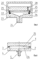
- FIG. 2 schematically and in cross section an inventive capacitive vacuum measuring cell.
- Fig. 3 is an enlarged view and a detail of the measuring cell according to FIG. 2.
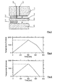
- Fig. 4 A temperature - time diagram for the sintering step Membrane.
- Fig. 5 A temperature-time diagram for a smoothing step the membrane.
- a capacitive measuring cell with a membrane according to the invention made of Al 2 O 3 with a structure essentially completely symmetrically arranged around the membrane is shown in cross section in FIG. 2.
- the first housing (1) consists of a ceramic plate made of Al 2 O 3 which is sealed at a distance of 2 ⁇ m to 50 ⁇ m relative to the ceramic membrane (2) in the edge area and includes a reference vacuum space (25).
- the distance between the two surfaces is usually set directly during assembly using the sealing material (3), which lies between the membrane edge and the housing edge. In this way, a completely flat housing plate (1) can be used.
- a measuring vacuum space (26) is formed in a second housing (4) on the opposite side of the membrane, which can be reached via a connecting piece (5) through an opening in the housing (4) for media to be measured.
- the seal (3) As mentioned, the distance on both sides of the membrane (2) defines the distance of the two housings (1 and 4).
- This seal is for example and preferably a glass solder, which is easy to handle and can be applied for example by screen printing.
- a typical measuring cell with an outer diameter of 38 mm and a free membrane inner diameter of 30 mm Distance (3) about 2 to 50 microns, preferably 12 to 35 microns.
- the first housing (1) is 5 mm thick
- the second housing (4) is preferred in the interior, as shown in Fig. 1, with an approx. 0.5 mm deep recess in order to close the measuring vacuum chamber (26) enlarge.
- the membrane (2) and the housing (1) are on the reference vacuum chamber side each with an electrically conductive layer (7) coated.
- the two layers are electrically connected to each other not connected.
- the layers (7) can, for example painted on, printed on, sprayed on or with a vacuum process be applied. They are preferably used with a Vacuum processes, such as applied by vapor deposition or sputtering.
- Gold which, for example, is particularly suitable as a layer material is evaporated with a layer thickness of 1 ⁇ m and afterwards using sputter etching to a few nanometers, for example 5 nm is thinned.
- the layer can thus be defined in thickness and thin enough to be tension-free.
- the electrical The membranes (7) are preferably connected with vacuum-tight, electrically conductive bushings (6), preferably through the housing (1), where it is then connected to the evaluation electronics can be connected.
- the drain pipe, which through the first housing plate (1) and the getter arrangement are not shown in Figure 3.
- FIG. 4 An example of an optimized time-temperature profile for the Sintering step of the membrane, starting from the green body, is in Figure 4 shown.
- sintering make sure that the membrane material has grain sizes after sintering, the are on average not larger than 20 ⁇ m, better not larger than 10 ⁇ m, preferably smaller than 5 ⁇ m, for high gas tightness or To ensure helium-tightness of the thin membrane.
- the thickness of the membrane should also be at least 2 grains, better 5 grains, should be present.
- the sintering step is the membrane by several mm compared to a plan Discarded area.
- the membrane is not yet usable and must be smoothed out that means that planities have to be achieved by the ideal flat area by no more than 10 ⁇ m, better by less than 5 ⁇ m. This is achieved by the Membrane, lying on a flat surface carefully up to your Softening is heated in an oven. She will then adapt to the flat surface with its own weight. To achieve better results, this process can be repeated and also the membrane between flat plates be pressed flat with slight pressure. It is particularly easy this when the diaphragm is loaded by its own weight the plates are made in the range of several 10 grams.
- the Membranes should be between the smoothing heating steps of the plan disassembled and twisted or put down again become. Two smoothing steps are usually sufficient and should be sought for economic reasons.
- FIG. 4 An example of an optimized time-temperature profile for one Smoothing step, starting from the one already sintered Membrane is shown in Figure 4.
- the membrane reaches a maximum temperature of 1570 ° C and remains below that the sintering temperature of 1630 ° C.
- the membrane will soft and can conform to the shaping, especially the plan Adjust the underlay using your own weight or weight.
Description
Die Erfindung bezieht sich auf eine Membrane für eine kapazitive
Vakuummesszelle gemäss Oberbegriff des Patentanspruches 1.The invention relates to a membrane for a capacitive
Vacuum measuring cell according to the preamble of
Es ist bekannt, Drücke bzw. Druckdifferenzen dadurch zu messen, indem eine dünne Membran druckbeaufschlagt wird und ihre Durchbiegung gemessen wird. Eine bekannte und geeignete Methode, die Durchbiegung solcher Membranen zu messen besteht darin, dass die Membrananordnung als variable elektrische Kapazität ausgebildet wird, wobei über eine Messelektronik in bekannter Weise die Kapazitätsänderung ausgewertet wird, welche mit der Druckänderung korreliert. Die Kapazität wird ausgebildet, indem die dünne, biegsame Membranfläche in geringem Abstand gegenüber einer weiteren Fläche angeordnet ist und beide einander gegenüberliegenden Oberflächen mit einem elektrisch leitenden Belag beschichtet oder aus elektrisch leitfähigem Material sind. Bei Druckbeaufschlagung der Membran verändert sich durch die Durchbiegung der Abstand zwischen den beiden Elektroden, was zu einer auswertbaren Kapazitätsänderung der Anordnung führt. Sensoren dieser Art werden in grossen Stückzahlen aus Silizium hergestellt. Sowohl der flächige Grundkörper wie auch die Membran bestehen hierbei oft vollständig aus Silizium-Material. Es gibt auch Ausführungen mit kombinierter Materialzusammensetzung z.B. Silizium mit Glasunterlage. Die Sensoren lassen sich dadurch kostengünstig herstellen. Für Vakuumanwendungen sind Drucksensoren dieser Art in der Regel nur für höhere Druckbereiche im Bereich von ca. 10-1 mbar bis einige bar einsetzbar. Hohe Auflösung bei tieferen Drücken ab etwa 10-1 mbar sind mit dem Werkstoff Silizium nicht mehr realisierbar. Unter anderem rührt dies daher, dass das Silizium an der Oberfläche mit der Umgebung reagiert und so die empfindliche Sensorcharakteristik gestört wird. Bereits Wasserdampf, der in normaler atmosphärischer Luft enthalten ist, führt zu entsprechenden Reaktionen an den Oberflächen. Das Problem wird zusätzlich verschärft, wenn der Sensor in chemisch aggressiven Atmosphären eingesetzt wird. Es wurde deshalb versucht, solche Silizium-Sensoren durch Passivieren der Oberflächen gegenüber aggressiven Ausseneinflüssen zu schützen. Es wurde auch versucht, die Oberfläche mit Schutzüberzügen zu versehen, damit die Haltbarkeit und Resistenz gegenüber der chemisch aggressiven Umgebung erhöht wird, wie dies in DE 41 36 987 beschrieben ist. Solche Massnahmen sind kostenaufwendig und führen bei mechanisch deformierbaren Teilen, wie Membranen, nur bedingt zum Erfolg, insbesondere bei besonders aggressiven Medien, wie Fluor, Bromsäure und deren Verbindungen, wie sie bei Vakuumätzverfahren eingesetzt werden.It is known to measure pressures or pressure differences by pressurizing a thin membrane and measuring its deflection. A known and suitable method for measuring the deflection of such membranes is that the membrane arrangement is designed as a variable electrical capacitance, the capacitance change, which correlates with the pressure change, being evaluated in a known manner via measuring electronics. The capacitance is formed in that the thin, flexible membrane surface is arranged at a short distance from another surface and both opposite surfaces are coated with an electrically conductive covering or are made of electrically conductive material. When the membrane is pressurized, the deflection changes the distance between the two electrodes, which leads to an evaluable change in the capacitance of the arrangement. Large numbers of sensors of this type are made of silicon. Both the flat base body and the membrane often consist entirely of silicon material. There are also versions with a combined material composition, e.g. silicon with a glass base. This enables the sensors to be manufactured inexpensively. For vacuum applications, pressure sensors of this type can generally only be used for higher pressure ranges in the range from approx. 10 -1 mbar to a few bar. High resolution at lower pressures from around 10 -1 mbar can no longer be achieved with silicon. Among other things, this stems from the fact that the surface of the silicon reacts with the environment, thus disrupting the sensitive sensor characteristics. Even water vapor, which is contained in normal atmospheric air, leads to corresponding reactions on the surfaces. The problem is further exacerbated when the sensor is used in chemically aggressive atmospheres. An attempt was therefore made to protect such silicon sensors against aggressive external influences by passivating the surfaces. Attempts have also been made to provide the surface with protective coatings so that the durability and resistance to the chemically aggressive environment is increased, as described in DE 41 36 987. Such measures are expensive and lead to only limited success with mechanically deformable parts, such as membranes, in particular with particularly aggressive media, such as fluorine, bromic acid and their compounds, as are used in vacuum etching processes.
Es wurde deshalb versucht, Druckmesszellen für Vakuumanwendungen vollständig aus korrosionsfesten Materialien wie Al2O3 herzustellen. Eine bekannte Anordnung dieser Art ist in Fig. 1 dargestellt. Die Messzelle besteht aus einer Keramikplatte (20), über deren Fläche in geringem Abstand eine Membran (22) angeordnet ist, welche gegenüber der Keramikplatte (20) im Randbereich mit einer Schmelzdichtung (21) dichtend verbunden ist. Die Keramikplatte (20) bildet so zusammen mit der Membran (22) einen Referenzvakuumraum (25) aus, der über eine Pumpöffnung bei der Herstellung evakuiert worden ist und mit einer Dichtung (28) abgedichtet ist. Die im Referenzvakuumraum (25) sich gegenüber liegenden Oberflächen der Keramikplatte (20) und der Membran (22) sind elektrisch leitend beschichtet und mit isolierten Anschlüssen nach aussen geführt, um das Kapazitätssignal mit einer Elektonik auszuwerten (in der Figur nicht dargestellt). Die Platte (20) und die Membran (22) sind beide, um Korrosionsbeständigkeit zu erreichen, aus Keramik-Material, wie Al2O3 gefertigt. Diese Messzelle ist wiederum in einem vakuumdichten Gehäuse (23) angeordnet, welches mit einem Messzellenanschluss (24) versehen ist, welche mit den zu messenden Medien verbunden werden. Der sich ausbildende Messvakuumraum (26) ist über den Messzellenanschluss (24) gegenüber der Membran (22) mit einer Elastomerdichtung (27) dichtend verbunden, so dass die zu messenden Drücke nur die Membranoberfläche (22) beaufschlagen. Zum Zweck der Abdichtung wird die ganze Zelle über die Keramikplatte (20) und die Membran (22) gegen die Elastomerdichtung (27) gedrückt. Messzellen dieser Art sind bis anhin nur für höhere Drücke im Bereich von 0,1 mbar bis 100 bar einsetzbar. Diese Bauweise führt ausserdem zu Verspannungen in den Materialien, was im tiefen Druckbereich, beispielsweise < 1 mbar die Reproduzierbarkeit der Messergebnisse und die Auflösung wesentlich beeinträchtigt. Die bisher verwendeten Keramikmembranen (22) weisen eine Dicke auf im Bereich von 279µm bis 2540µm. Solche Konstruktionen ermöglichen es nicht, grosse Messbereiche insbesondere bis zu tiefen Drücken von 0,1 mbar bis 10-6 mbar zu realisieren, ausserdem sind Konstruktionen dieser Art, wie sie auch in der US 5,553,502 offenbart sind, kostenaufwendig.An attempt was therefore made to manufacture pressure measuring cells for vacuum applications entirely from corrosion-resistant materials such as Al 2 O 3 . A known arrangement of this type is shown in Fig. 1. The measuring cell consists of a ceramic plate (20), over the surface of which a membrane (22) is arranged at a short distance, which is connected to the ceramic plate (20) in the edge area with a sealing seal (21). The ceramic plate (20) thus forms, together with the membrane (22), a reference vacuum space (25), which was evacuated via a pump opening during manufacture and is sealed with a seal (28). The surfaces of the ceramic plate (20) and the membrane (22) lying opposite one another in the reference vacuum space (25) are coated in an electrically conductive manner and are led outwards with insulated connections in order to evaluate the capacitance signal with electronics (not shown in the figure). The plate (20) and the membrane (22) are both made of ceramic material, such as Al 2 O 3 , in order to achieve corrosion resistance. This measuring cell is in turn arranged in a vacuum-tight housing (23) which is provided with a measuring cell connection (24) which is connected to the media to be measured. The measuring vacuum space (26) that forms is connected via the measuring cell connection (24) to the membrane (22) with an elastomer seal (27) so that the pressures to be measured only act on the membrane surface (22). For the purpose of sealing, the entire cell is pressed against the elastomer seal (27) via the ceramic plate (20) and the membrane (22). So far, measuring cells of this type can only be used for higher pressures in the range from 0.1 mbar to 100 bar. This design also leads to tension in the materials, which significantly impairs the reproducibility of the measurement results and the resolution in the low pressure range, for example <1 mbar. The ceramic membranes (22) used up to now have a thickness in the range from 279 µm to 2540 µm. Such constructions do not make it possible to realize large measuring ranges, in particular down to low pressures of 0.1 mbar to 10 -6 mbar, and constructions of this type, as are also disclosed in US Pat. No. 5,553,502, are costly.
Die vorliegende Erfindung hat es sich zur Aufgabe gemacht, die Nachteile des Standes der Technik zu beseitigen. Insbesondere stellt sich die vorliegende Erfindung die Aufgabe, eine einfach und kostengünstig herstellbare Membrane aus Al2O3 für eine Vakuummesszelle zu realisieren, welche es erlaubt, Drücke im Bereich von 10-6 mbar bis 1000 mbar, insbesondere von 10-6 mbar bis 1 mbar mit Genauigkeiten von besser 1%, vorzugsweise besser 0,3% vom Messwert zu messen. Der Messbereich kann hierbei durch mehrere erfindungsgemässe Zellen- bzw. Membranausführungen abgedeckt werden. Zudem soll die Membrane gegen aggressive Medien korrosionsbeständig sein.The present invention has set itself the task of eliminating the disadvantages of the prior art. In particular, the object of the present invention is to implement a membrane made of Al 2 O 3 that is simple and inexpensive to produce for a vacuum measuring cell, which allows pressures in the range from 10 -6 mbar to 1000 mbar, in particular from 10 -6 mbar to 1 mbar with an accuracy of better than 1%, preferably better than 0.3% of the measured value. The measuring range can be covered by several cell or membrane designs according to the invention. In addition, the membrane should be corrosion-resistant against aggressive media.
Die Aufgabe wird bei der gattungsgemässen Membrane gemäss den
kennzeichnenden Merkmalen des Patentanspruches 1 gelöst. Die
abhängigen Patentansprüche beziehen sich auf vorteilhafte weitere
Ausgestaltungen der Erfindung.The task is in the generic membrane according to the
characterizing features of
Die erfindungsgemässe Membrane ist vollständig aus einer Keramik, wie insbesondere Al2O3 hergestellt. Dadurch wird sehr hohe Korrosionsbeständigkeit und langlebige Reproduzierbarkeit erreicht. Ein Messzellenaufbau kann somit vollständig aus korrosionsbeständigen Materialien, insbesondere aus Keramik hergestellt werden. Nur in Bereichen, wo gedichtet werden muss oder wo Durchführungen vorgesehen sind, werden in geringen Mengen andere Materialien als Al2O3 vorgesehen, sofern nicht das Al2O3 ohne Fremdmaterialzugabe verschweisst wird. Eine Zelle besteht aus einem ersten plattenförmigen Gehäusekörper, über welchem eine Membran im Randbereich dichtend angeordnet ist, so dass diese einen Referenzvakuumraum einschliesst. Auf der dem Referenzvakuumraum abgewandten Seite ist ein zweiter Gehäusekörper ebenfalls im Randbereich dichtend schliessend beabstandet angeordnet, so dass dort ein Messvakuumraum ausgebildet wird. Dieser Messvakuumraum ist mit einem Anschluss für die Zuleitung des zu messenden Mediums versehen. Die Oberflächen des ersten Gehäusekörpers und der Membrane, welche den Referenzvakuumraum ausbilden, sind elektrisch leitend beschichtet, beispielsweise mit Gold, und bilden die Elektroden der Kapazitätsmesszelle. Die Elektroden wiederum sind herausgeführt, beispielsweise durch den ersten Gehäusekörper oder durch den Abdichtungsbereich in der Randzone. Die im wesentlichen parallel angeordneten Elektrodenflächen weisen einen Abstand im Bereich von 2µm bis 50µm auf. Die Abdichtung der Membran im Randbereich gegenüber den beiden Gehäusen erfolgt vorzugsweise durch Verschweissung, beispielsweise durch Laserschweissen. Sehr geeignet und einfach in der Anwendung ist aber auch ein Glaslot, welches ebenfalls korrosionsbeständig ist. Eine weitere Möglichkeit der dichtenden Verbindung besteht auch darin, Gehäuseteile diffusiv zu verbinden, beispielsweise im Grünkörperstadium, wenn es darum geht, Al2O3-fremdes Material vollständig zu vermeiden.The membrane according to the invention is made entirely of a ceramic, such as in particular Al 2 O 3 . This ensures very high corrosion resistance and long-lasting reproducibility. A measuring cell assembly can thus be made entirely of corrosion-resistant materials, in particular ceramic. Only in areas where sealing has to be carried out or where bushings are provided are materials other than Al 2 O 3 provided in small quantities, unless the Al 2 O 3 is welded without the addition of foreign material. A cell consists of a first plate-shaped housing body, over which a membrane is sealingly arranged in the edge area, so that it encloses a reference vacuum space. On the side facing away from the reference vacuum space, a second housing body is also sealingly spaced in the edge region, so that a measurement vacuum space is formed there. This measuring vacuum chamber is provided with a connection for the supply of the medium to be measured. The surfaces of the first housing body and the membrane, which form the reference vacuum space, are coated in an electrically conductive manner, for example with gold, and form the electrodes of the capacitance measuring cell. The electrodes in turn are led out, for example through the first housing body or through the sealing area in the edge zone. The electrode surfaces, which are arranged essentially in parallel, are at a distance in the range from 2 μm to 50 μm. The membrane in the edge region is preferably sealed off from the two housings by welding, for example by laser welding. A glass solder, which is also corrosion-resistant, is also very suitable and easy to use. Another possibility of the sealing connection is to connect housing parts diffusively, for example in the green body stage, when it is a matter of completely avoiding material foreign to Al 2 O 3 .
Die erfindungsgemässe Membrane in der vorerwähnten Messzellenanordnung ermöglicht im Wesentlichen einen symmetrischen Aufbau, der jegliche Verspannungen im Gehäuse vermeidet. Dies ist besonders wichtig, um eine hohe Messempfindlichkeit zu erreichen und tiefe Messdrücke bei hoher Genauigkeit und Reproduzierbarkeit zu realisieren. Dadurch wird ausserdem ermöglicht, die erfindungsgemäss sehr dünne Membran aus Keramik zu verwenden, welche zwingend isc, wenn die Messzelle tiefere Vakuumdrücke als 100 mbar, und vor allem tiefer als 10 mbar, zuverlässig mit kapazitiven vollkeramischen Messzellen erfassen soll. Hierzu sind Membrandicken von 10µm bis 250µm notwendig, wobei Membrandicken von 10µm bis 120µm bevorzugt werden, um eine sehr gute Auflösung zu erreichen. Typische Membrandickenbereiche sind beispielsweise:
- bei 1000 Torr Membrandicke 760µm ± 10µm
- bei 100 Torr Membrandicke 345µm ± 10µm
- bei 10 Torr Membrandicke 150µm ± 10µm
- bei 1 Torr Membrandicke 100µm ± 10µm
- bei 0,1 Torr Membrandicke 60µm ± 10µm
- bei 0,01 Torr Membrandicke 40µm ± 10µm
- at 1000 Torr membrane thickness 760µm ± 10µm
- at 100 Torr membrane thickness 345µm ± 10µm
- at 10 Torr membrane thickness 150µm ± 10µm
- at 1 Torr membrane thickness 100µm ± 10µm
- at 0.1 Torr membrane thickness 60µm ± 10µm
- at 0.01 Torr membrane thickness 40µm ± 10µm
Solch dünne Membranen sind besonders schwierig herzustellen und benötigen nach dem Sinterschritt mindestens einen weiteren Glättungsschritt. Es ist ausserdem besonders wichtig, dass die Membran genügend Heliumdichtheit aufweist, was nur erreicht werden kann, wenn die Korngrössen des Membranmaterials nicht zu gross sind und sich im Bereich von < 20µm bewegen. Kleinere Korngrössen von < 10µm werden bevorzugt, insbesondere solche die < 5µm sind. In jedem Fall müssen im Querschnitt der Membran über die Dicke betrachtet mindestens zwei Körner vorhanden sein, bei mehr als fünf Körnern übereinander sind die Membranen besonders dicht.Such thin membranes are particularly difficult to manufacture and need at least one more after the sintering step Smoothing step. It is also particularly important that the Membrane has sufficient helium tightness, which only achieves can be if the grain sizes of the membrane material do not increase are large and are in the range of <20µm. smaller Grain sizes of <10 μm are preferred, especially those which are <5µm. In any case, the cross section of the membrane Considered at least two grains across the thickness If there are more than five grains one above the other, the membranes are particularly dense.
Ein weiteres wichtiges Kriterium für die erreichbare Genauigkeit der Messzelle ist die Planität der Membranfläche. Die Unebenheit über die gesamte Fläche sollte in jedem Fall nicht mehr als 30 % des Elektrodenabstandes betragen, wobei es besser ist, wenn sie nicht mehr als 15 % beträgt. Dies bedeutet, dass die Unebenheit über die gesamte Fläche nicht grösser als 10µm sein sollte, vorzugsweise nicht mehr als 5µm. Die Unebenheit ist hierbei definiert als die Differenz vom tiefsten zum höchsten Punkt. Die Reinheit des verwendeten Aluminiumoxides der Membrane sollte, um entsprechend gute Langzeitstabilität zu erreichen, mindestens 94 % betragen, wobei bevorzugte Werte über 99 % liegen.Another important criterion for the accuracy that can be achieved the measuring cell is the flatness of the membrane surface. The bump in any case should not cover the entire area Be more than 30% of the electrode gap, being better is if it is not more than 15%. This means that the unevenness over the entire area is not larger than 10 µm should be, preferably not more than 5 µm. The bump is defined as the difference from the lowest to the highest Point. The purity of the aluminum oxide used In order to achieve good long-term stability, the membrane should be at least 94%, with preferred values above 99% lie.
Um die Qualität der im Randbereich liegenden Membrandichtung nicht zu beeinflussen, ist es vorteilhaft, wenn die elektrisch leitenden Schichten über Durchführungen, welche am ersten Gehäusekörper angeordnet sind, herausgeführt werden, und nicht direkt über die Membrandichtung bzw. -verschweissung.The quality of the membrane seal in the edge area not to influence, it is advantageous if the electrical conductive layers over bushings, which on the first housing body are arranged, are led out, and not directly over the membrane seal or welding.
Der Referenzvakuumraum muss ein langzeitstabiles Vakuum hoher Qualität aufweisen, um die präzise Funktion der Messzelle über lange Zeit gewährleisten zu können. Dazu ist nach dem Abpumpen ein Getter vorzusehen, welcher vorzugsweise in einem kleinen Volumen am ersten Gehäuse angeordnet ist und in Verbindung mit dem Referenzvakuumraum steht. Dieser Getter sorgt dafür, dass der Referenzvakuumdruck tiefer liegt als der zu messende Druck, vorzugsweise aber um mindestens eine Dekade tiefer. Um Verunreinigungen des Innenbereiches der Messzelle zu vermeiden, sollte ein Gettertyp gewählt werden, der nicht verdampfend ist.The reference vacuum space must have a long-term stable vacuum Have quality to ensure the precise function of the measuring cell to be able to guarantee for a long time. This is after pumping out to provide a getter, which is preferably in a small Volume is arranged on the first housing and in connection with the reference vacuum space. This getter ensures that the reference vacuum pressure is lower than the pressure to be measured, but preferably at least a decade lower. To impurities to avoid the inside of the measuring cell, a getter type should be chosen that is not vaporizing.
Messzellen mit einer erfindungsgemässen Membrane können sehr kompakt und kostengünstig aufgebaut werden. Der Durchmesser einer solchen Zelle kann im Bereich von 5 bis 80 mm liegen, wobei bevorzugterweise die Messzelle einen Durchmesser von 5 bis 40 mm aufweist. Die Dicke einer solchen Zelle liegt hierbei vorzugsweise im Bereich von 2 mm bis 25 mm.Measuring cells with a membrane according to the invention can do a lot be built compactly and inexpensively. The diameter of one such cell can range from 5 to 80 mm, where preferably the measuring cell has a diameter of 5 to 40 mm. The thickness of such a cell is preferably in this case in the range from 2 mm to 25 mm.
Zur Herstellung einer funktionsfähigen Messzelle mit den vorerwähnten Eigenschaften ist die Einhaltung des entsprechenden Herstellverfahrens sehr wichtig. Insbesondere die Herstellung der dünnen Keramikmembrane fordert besondere Massnahmen. Sowohl die Membrane wie der ganze Aufbau der Messzelle muss besonders eigenspannungsfrei erfolgen.For the production of a functional measuring cell with the aforementioned Compliance is the corresponding property Manufacturing process very important. Manufacturing in particular the thin ceramic membrane requires special measures. Either the membrane and the entire structure of the measuring cell must be special free of residual stress.
Erfindungsgemässe Membranen aus Al2O3 werden dadurch hergestellt, dass, wie im Keramikbereich üblich, zuerst ein Schlikker nach einem bestimmten Rezept gemischt wird und die teigförmige Masse danach auf ein bandförmiges Trägermaterial, beispielsweise eine Kunststofffolie, dünn und gleichmässig aufgebracht wird. Nach dem Trocknen werden diese Folien auf Fehlstellen geprüft, wie Blasen oder Löcher. Die nun vorliegende Masse, welche noch nicht gesintert und somit noch flexibel ist, wird als Grünkörper bezeichnet. Die gewünschte Membranform, vorzugsweise kreisrund, wird nun aus dem bandförmigen Grünkörpermaterial herausgeschnitten, wobei dieses hierbei noch an der Folie haftet. Geschnitten wird beispielsweise mit Messern, vorzugsweise mit einem Laser. Das Ausschneiden bzw. Ritzen des Grünkörpers muss besonders vorsichtig erfolgen, so dass gegen die Fläche der zukünftigen Keramikmembran an der Schneidkante keine Verwerfungen bzw. Erhebungen das Mass der Welligkeit der Membran mitbestimmend entstehen. Wenn mit dem Messer geschnitten wird, kann hierfür beispielsweise gleichzeitig mit dem Schneidvorgang membranseitig ein Anpressrädchen mitgeführt werden, welches ein zu starkes Aufwerfen des Grünkörpers verhindert. Anschliessend erfolgt ein sorgfältiges Trennen der vorzugsweise in Kreisform ausgeschnittenen Membran von der Folie, indem diese beispielsweise über eine Kante abgezogen wird. Die Membranen werden anschliessend in einem Ofen gesintert. Für die Sinterung werden die Membranen vorzugsweise auf hartgebrannte, plane Al2O3-Platten gelegt und beispielsweise übereinander beabstandet gestapelt und bei typischerweise 1630°C gesintert. Die Temperatur wird während etwa 400 Minuten auf diese 1630°C hochgefahren, also etwa mit 4°C Temperaturanstieg pro Minute, dann einige Minuten, beispielsweise 6 Minuten, auf dieser Temperatur belassen und danach in einem ersten Schritt mit langsamer Temperaturerniedrigung von 3°C pro Minute während etwa 210 Minuten auf 1000°C abgesenkt und in einem weiteren, zweiten Schritt mit einer Temperaturerniedrigung von 6°C in der Minute während etwa 170 Minuten wieder auf Umgebungstemperatur abgekühlt. Es liegt nun eine Keramikmembran vor, die gegenüber dem Grünkörper ein hartes, reines Keramikgefüge aufweist, wobei die Additive des Grünkörpermateriales verdampft sind. Nach diesem Sinterschritt ist die Membrane stark uneben und weist Verwerfungen auf von mehreren Millimetern bei einem Durchmesser von etwa 40 mm.Membranes according to the invention made of Al 2 O 3 are produced by, as is customary in the field of ceramics, first mixing a slip according to a specific recipe and then applying the dough-like mass thinly and uniformly to a band-shaped carrier material, for example a plastic film. After drying, these foils are checked for defects, such as bubbles or holes. The mass now present, which has not yet been sintered and is therefore still flexible, is called the green body. The desired membrane shape, preferably circular, is now cut out of the ribbon-shaped green body material, this still adhering to the film. Cutting is carried out, for example, with knives, preferably with a laser. The green body must be cut out or scored with particular care, so that there are no distortions or raised portions against the surface of the future ceramic membrane on the cutting edge, which also determines the degree of waviness of the membrane. If the knife is used for cutting, a contact wheel can be carried out for this purpose at the same time as the cutting process, which prevents the green body from being thrown up too much. The membrane, which is preferably cut out in a circular shape, is then carefully separated from the film, for example by pulling it off over an edge. The membranes are then sintered in an oven. For the sintering, the membranes are preferably placed on hard-fired, flat Al 2 O 3 plates and, for example, stacked at a distance from one another and sintered at typically 1630 ° C. The temperature is raised to this 1630 ° C for about 400 minutes, i.e. with a temperature rise of 4 ° C per minute, then left at this temperature for a few minutes, for example 6 minutes, and then in a first step with a slow temperature decrease of 3 ° C per minute Minute reduced to 1000 ° C for about 210 minutes and cooled again to ambient temperature in a further, second step with a temperature decrease of 6 ° C per minute for about 170 minutes. There is now a ceramic membrane which has a hard, pure ceramic structure with respect to the green body, the additives of the green body material having evaporated. After this sintering step, the membrane is very uneven and has warpage of several millimeters with a diameter of about 40 mm.
Die Membrane kann in diesem Zustand, wegen den starken Verwerfungen und Eigenspannungen im Material noch nicht verwendet werden. Die Membrane muss mit mindestens einem weiteren Schritt geglättet werden. Dies erfolgt dadurch, dass die Membrane einem weiteren Heizschritt im Ofen unterzogen wird. Hierbei werden die Membranen vorsichtig zwischen massive und sehr plane hartgesinterte Al2O3-Platten (auch "dead"-Al2O3, d.h. grosskörnige) gelegt, welche bei einem Membrandurchmesser von 40mm vorzugsweise ein Gewicht von einigen 10 bis einigen 100 Gramm, wie im Beispiel etwa 60 Gramm, aufweisen oder entsprechend beschwert sind. Die Temperatur wird während etwa 390 Minuten mit 4°C pro Minute langsam auf etwa 1570°C hochgefahren. Nach einer kurzen Verweilzeit von einigen Minuten, etwa 25 Minuten, auf dieser Temperatur wird die Temperatur wiederum langsam abgesenkt, während etwa 115 Minuten mit etwa 5°C pro Minute, bis 1000°C erreicht worden sind. Danach wird die Temperatur mit etwa 6°C pro Minute weiter abgesenkt, während etwa 166 Minuten, bis Umgebungstemperatur erreicht wird. Nach einem solchen Glättungsschritt erscheint die Membran nur noch mit einer sehr geringen Verwerfung von einigen zehntel Millimetern. Wichtig bei diesem Glättungsschritt ist, dass die Temperatur gegenüber dem ersten Sinterheizschritt weniger hoch ist, vorzugsweise bis maximal 100°C unter der Sintertemperatur liegt. Um gute Ergebnisse zu erzielen, wie sie für die geforderte Messzellenqualität notwendig sind, muss dieser Glättungsheizschritt mindestens zweimal durchgeführt werden. Aus wirtschaftlichen Gründen sollten die Glättungsheizschritte so durchgeführt werden, dass nicht mehr als zwei Glättungsschritte notwendig sind. Besonders gute Ergebnisse werden dadurch erzielt, dass zwischen den Glättungsheizschritten die Membran sorgfältig von der Platte abgelöst wird und in etwas versetzter Position wieder abgelegt wird. Sie kann mit Vorzug sogar umgedreht abgelegt werden. Die Verwendung eines Stapels von mehreren planen Platten mit dazwischenliegenden Membranen macht die Anordnung besonders wirtschaftlich.The membrane cannot be used in this condition due to the strong distortions and residual stresses in the material. The membrane must be smoothed with at least one further step. This is done by subjecting the membrane to a further heating step in the furnace. Here, the membranes are carefully placed between solid and very flat hard sintered Al 2 O 3 plates (also "dead" -Al 2 O 3 , ie large-grained), which preferably have a weight of a few 10 to a few 100 grams with a membrane diameter of 40mm, as in the example, about 60 grams, or are weighted accordingly. The temperature is slowly ramped up to about 1570 ° C at 4 ° C per minute for about 390 minutes. After a short residence time of a few minutes, about 25 minutes, at this temperature, the temperature is slowly lowered again, while about 115 minutes at about 5 ° C. per minute to 1000 ° C. have been reached. Thereafter, the temperature is further lowered at about 6 ° C per minute, for about 166 minutes until ambient temperature is reached. After such a smoothing step, the membrane appears only with a very small warp of a few tenths of a millimeter. It is important in this smoothing step that the temperature is less high than the first sintering step, preferably up to a maximum of 100 ° C. below the sintering temperature. In order to achieve good results, which are necessary for the required measuring cell quality, this smoothing heating step must be carried out at least twice. For economic reasons, the smoothing heating steps should be carried out in such a way that no more than two smoothing steps are necessary. Particularly good results are achieved in that the membrane is carefully detached from the plate between the smoothing heating steps and put down again in a somewhat offset position. It can even be stored upside down. The use of a stack of several flat plates with membranes in between makes the arrangement particularly economical.
Für die Funktionsfähigkeit von Messzellen der vorerwähnten Art, ist die Qualität der Membrane entscheidend. Das vorerwähnte Herstellungsverfahren ermöglicht die Herstellung von dünnen Membranen hoher Dichtheit bei sehr guter Planität. Die Einhaltung entsprechender Parameter beim Sintern und beim anschliessenden Glättungsschritt sind hierbei relevant. Beim Sintern müssen Maximaltemperaturen erreicht werden von 1300 bis 1800 °C, vorzugsweise von 1400 bis 1700 °C. Dieses Temperaturmaximum sollte zumindest kurz erreicht werden, aber maximal 180 Minuten lang in diesem Bereich gehalten werden. Die Aufheizgeschwindigkeit soll maximal 25 °C pro Minute betragen. Vorzugsweise wird das Aufheizen in zwei Schritte unterteilt. Nach Erreichen von 1000 bis 1300 °C soll das weitere Aufheizen bis auf Endtemperatur mit geringerer Geschwindigkeit erfolgen, mit maximal 15 °C pro Minute. Nach dem Erreichen bzw. Halten der vorerwähnten Maximaltemperatur wird die Membrane wieder abgekühlt, mit einer Geschwindigkeit von maximal 25 °C pro Minute. Bei einem zu raschen Aufheizen und/oder Abkühlen werden die Membranen stark wellig und porös. Längere Zeiten schaden nicht, sind aber nicht wirtschaftlich.For the functionality of measuring cells of the aforementioned type, the quality of the membrane is crucial. The aforementioned Manufacturing process enables the production of thin Membranes of high density with very good flatness. Compliance corresponding parameters for sintering and the subsequent one Smoothing step are relevant here. When sintering maximum temperatures must be reached from 1300 to 1800 ° C, preferably from 1400 to 1700 ° C. This temperature maximum should be achieved at least briefly, but a maximum of 180 minutes long in this area. The heating rate should be a maximum of 25 ° C per minute. Preferably the heating is divided into two steps. After reaching The further heating up to the final temperature should be between 1000 and 1300 ° C at a slower speed, with a maximum of 15 ° C per minute. After reaching or maintaining the aforementioned maximum temperature the membrane is cooled down again with a Maximum speed of 25 ° C per minute. To snap at one Heating and / or cooling the membranes become strong wavy and porous. Longer times don't hurt, but they are not economically.
Beim Glätten müssen dieselben Bedingungen eingehalten werden wie beim Sintern, wobei die Glättungstemperatur die maximale Sintertemperatur nie überschreiten darf. Vorzugsweise bleibt diese bis maximal 100 °C unter der Sintertemperatur.The same conditions must be observed when smoothing as with sintering, the smoothing temperature being the maximum Never exceed the sintering temperature. Preferably remains this up to a maximum of 100 ° C below the sintering temperature.
Es liegen nun Membranen vor, die wahlweise Dicken im Bereich von 10µm bis 250µm, vorzugsweise < 120µm aufweisen können. Mit dem vorliegenden Verfahren können Planitäten der Membranen erreicht werden, die besser als 10µm über die gesamte Fläche sind, vorzugsweise sogar besser als 5µm. Die Körner des Membranmateriales sind dabei im Mittel kleiner als 20µm, vorzugsweise kleiner als 10µm, wobei sogar solche, die kleiner als 5µm sind erzielt werden können. Dadurch kann auch die Forderung, dass über die Dicke mindestens zwei Körner vorhanden sein müssen, besser sogar mindestens fünf Körner, ohne weiteres erreicht werden. Somit können heliumdichte Membranen realisiert werden, welche für die Messzellenanforderung notwendig sind. Die Membran ist nun bereit für die Weiterverwendung im Messzellenaufbau.There are now membranes, the optional thicknesses in the range from 10 µm to 250 µm, preferably <120 µm. With In the present method, flatness of the membranes can be achieved that are better than 10µm over the entire area are, preferably even better than 5 µm. The grains of the membrane material are on average smaller than 20 µm, preferably smaller than 10 µm, even those smaller than 5 µm are can be achieved. As a result, the requirement that there must be at least two grains across the thickness, better even at least five grains, easily achieved become. Helium-tight membranes can thus be realized which are necessary for the measuring cell requirement. The membrane is now ready for further use in the measuring cell assembly.
Die Membran sowie eine plane Oberfläche des ersten Gehäusekörpers aus Al2O3 wird nun mit einem elektrisch leitenden Belag für die Ausbildung der Elektroden versehen. Dazu kann beispielsweise eine metallhaltige, beispielsweise eine goldhaltige Farbe verwendet werden, die beispielsweise aufgepinselt, aufgesprayt oder vorzugsweise aufgedruckt wird. Eine weitere Methode besteht darin, die elektrisch leitende Schicht mit Vakuumaufdampfen zu erzeugen, vorzugsweise mit Sputtern. Um die Schicht präzise und definiert erstellen zu können, ist es von Vorteil, wenn beispielsweise eine Goldschicht, die zuerst relativ dick, etwa 1µm, aufgebracht wird, anschliessend im inneren Bereich wieder abgedünnt wird, bis auf einige Nanometer Dicke, etwa 5 nm, mit einem Ätzverfahren, wie vorzugsweise einem Ionen- bzw. Sputterätzen. Auf diese Art entsteht ein dickerer Randbereich welcher, wenn beispielsweise gelötet wird, eine Diffusionssperre bildet. Ein praktisch einfach anwendbares und bevorzugtes Verfahren besteht darin, dass zuerst eine dünne Schicht von einigen nm über die ganze Fläche aufgebracht wird und danach am Rand eine dickere Schicht Gold mit Siebdruck (d.h. mit Kombinationsverfahren und verschiedenen Schichtdicken). Solchermassen behandelte Membranen, bzw. Gehäuse werden anschliessend getempert mit Temperaturen von einigen 100°C, vorzugsweise im Bereich von 650°C.The membrane and a flat surface of the first housing body made of Al 2 O 3 are now provided with an electrically conductive coating for the formation of the electrodes. For this purpose, for example, a metal-containing, for example a gold-containing paint can be used, which is, for example, brushed on, sprayed on or preferably printed on. Another method is to produce the electrically conductive layer using vacuum evaporation, preferably using sputtering. In order to be able to create the layer precisely and in a defined manner, it is advantageous if, for example, a gold layer, which is first applied relatively thickly, approximately 1 μm, is then thinned again in the inner region, down to a few nanometers thick, approximately 5 nm an etching process, such as preferably an ion or sputter etching. In this way, a thicker edge area is created which, for example when soldering, forms a diffusion barrier. A practically easy to use and preferred method consists in first applying a thin layer of a few nm over the entire surface and then a thicker layer of gold with screen printing on the edge (ie using a combination method and different layer thicknesses). Membranes or housings treated in this way are then annealed at temperatures of a few 100 ° C., preferably in the range of 650 ° C.
Das zweite Keramikgehäuse, welches messeitig angeordnet wird, besteht aus einer planen Keramikplatte, welche membranseitig eine flächige Ausnehmung aufweisen kann, um einen genügend grossen Messvakuumraum zu bilden. Der Anschlusstutzen wird an diesem Keramikgehäuse durch Schweissen, Kleben oder Löten, vorzugsweise mit einem Glaslot, so verbunden, dass die Anschlussöffnung mit dem zukünftigen Messvakuumraum kommunizieren kann.The second ceramic housing, which is arranged on the measurement side, consists of a flat ceramic plate, which on the membrane side can have a flat recess to a sufficiently large To form the measurement vacuum space. The connecting piece is on this Ceramic housing by welding, gluing or soldering, preferably with a glass solder, connected so that the connection opening can communicate with the future vacuum room.
Die Membrane wird im peripheren Bereich, wo die Dichtung erfolgt, beidseitig mit einer Glaspaste versehen, vorzugsweise mit einem Siebdruckverfahren. Nach dem Trocknen wird die Membrane mit der Glaspaste in einem Ofen bei einigen 100°C, vorzugsweise bei etwa 670°C, eingebrannt. Danach wird die Glasoberfläche beidseitig poliert, wobei vorzugsweise auch der zukünftige Elektrodenabstand definiert wird.The membrane is in the peripheral area where the seal takes place provided with glass paste on both sides, preferably with a screen printing process. After drying the membrane with the glass paste in an oven at some 100 ° C, preferably at about 670 ° C, baked. After that, the glass surface polished on both sides, preferably also the future one Electrode distance is defined.
Das elektrodenseitige, obere Keramikgehäuse kann zusätzlich auf der Aussenseite mit Hilfe des bereits erwähnten Beschichtungsprozesses, mit einer elektrisch leitenden Schicht versehen werden, um eine Abschirmung zu bilden. Ausserdem werden auch hier die Anschlusstellen am Gehäuse angebracht. In einem weiteren Schritt werden die Bohrungen für die elektrische Durchführung für die Elektrodenanschlüsse metallisiert, vorzugsweise mit Silber.The upper ceramic housing on the electrode side can also be opened the outside with the help of the already mentioned coating process, be provided with an electrically conductive layer, to form a shield. In addition, here too the connection points attached to the housing. In another Step will be the holes for the electrical feedthrough metallized for the electrode connections, preferably with Silver.
In einer Testphase wird das erste Gehäuse mit der Elektrode und den Durchführungen, zusammen mit der aufgelegten Membran, auf Dichtigkeit und auf die Elektrodendistanz geprüft. Danach wird der untere Gehäuseteil aufgelegt und der ganze Aufbau gewichtsbelastet, um ebenfalls die Funktion und die Distanzen zu testen. Anschliessend erfolgt in einem Montagerahmen allenfalls zusätzlich das Aufsetzen des Getteranschlusses und unter Gewichtsbelastung von etwa 200 Gramm ein Einbrennen der Glasdichtungen bei einigen 100°C, vorzugsweise bei etwa 630°C, und anschliessend ein Test, ob die erforderlichen Abstände eingehalten werden. Allenfalls kann durch weitere Gewichtsbelastung oder -entlastung und einen weiteren Brennvorgang der Membranabstand korrigiert werden. Der Vorgang des Dichtens muss sehr sorgfältig erfolgen und wie bereits erwähnt sollten bei der Messzellenanordnung keine Spannungen auftreten. Alternativ kann anstelle von Glaslot oder anderen Abdichtungsmitteln auch eine direkte Verschweissung erfolgen, vorzugsweise eine Laserverschweissung.In a test phase, the first housing with the electrode and the bushings, together with the membrane Tightness and checked for the electrode distance. After that the lower part of the housing is put on and the entire structure is weight-loaded, to also test the function and the distances. Then at most in a mounting frame additionally putting on the getter connection and under weight load of about 200 grams burned in the glass seals at some 100 ° C, preferably at about 630 ° C, and then a test of whether the required distances have been maintained become. At most it can be caused by additional weight or relief and a further burning process of the membrane distance Getting corrected. The process of poetry must be very should be done carefully and, as already mentioned, at Measuring cell arrangement no voltages occur. Alternatively, you can instead of glass solder or other sealants, one direct welding takes place, preferably a laser welding.
Die Erfindung wird nun anhand von Figuren schematisch und beispielsweise beschrieben.The invention will now be illustrated schematically and with reference to figures, for example described.
Fig. 2 schematisch und im Querschnitt eine erfindungsgemässe kapazitive Vakuummesszelle.Fig. 2 schematically and in cross section an inventive capacitive vacuum measuring cell.
Fig. 3 eine vergrösserte Darstellung und einen Ausschnitt aus der Messzelle nach Fig. 2.Fig. 3 is an enlarged view and a detail of the measuring cell according to FIG. 2.
Fig. 4 Ein Temperatur - Zeit Diagramm für den Sinterschritt der Membran. Fig. 4 A temperature - time diagram for the sintering step Membrane.
Fig. 5 Ein Temperatur - Zeit Diagramm für einen Glättungsschritt der Membran.Fig. 5 A temperature-time diagram for a smoothing step the membrane.
Eine kapazitive Messzelle mit einer erfindungsgemässen Membrane aus Al2O3 mit im wesentlichen vollständig um die Membran symmetrisch angeordnetem Aufbau ist im Querschnitt in Fig. 2 dargestellt. Das erste Gehäuse (1) besteht aus einer Keramikplatte aus Al2O3 welches in einem Abstand von 2µm bis 50µm gegenüber der keramischen Membran (2) im Randbereich dichtend verbunden ist und einen Referenzvakuumraum (25) einschliesst. Der Abstand zwischen den beiden Flächen wird in der Regel direkt beim Montieren über das Dichtungsmaterial (3), welches zwischen dem Membranrand und dem Gehäuserand liegt, eingestellt. Auf diese Weise kann eine vollständig plane Gehäuseplatte (1) verwendet werden. Auf die gleiche Art und Weise wird in einem zweiten Gehäuse (4) auf der gegenüberliegenden Membranseite ein Messvakuumraum (26) ausgebildet, welcher über einen Anschluss-Stutzen (5) durch eine Öffnung im Gehäuse (4) für zu messende Medien erreichbar ist.A capacitive measuring cell with a membrane according to the invention made of Al 2 O 3 with a structure essentially completely symmetrically arranged around the membrane is shown in cross section in FIG. 2. The first housing (1) consists of a ceramic plate made of Al 2 O 3 which is sealed at a distance of 2 µm to 50 µm relative to the ceramic membrane (2) in the edge area and includes a reference vacuum space (25). The distance between the two surfaces is usually set directly during assembly using the sealing material (3), which lies between the membrane edge and the housing edge. In this way, a completely flat housing plate (1) can be used. In the same way, a measuring vacuum space (26) is formed in a second housing (4) on the opposite side of the membrane, which can be reached via a connecting piece (5) through an opening in the housing (4) for media to be measured.
In Fig. 3 ist ein vergrösserter Ausschnitt des Randbereiches einer Messzelle im Querschnitt dargestellt. Die Dichtung (3) beidseitig der Membran (2) definiert wie erwähnt den Abstand der beiden Gehäuse (1 und 4). Diese Dichtung ist beispielsweise und bevorzugt ein Glaslot, welches einfach handhabbar ist und beispielsweise durch Siebdruck aufgebracht werden kann. In einer typischen Messzelle mit einem Aussendurchmesser von 38 mm und einem freien Membran-Innendurchmesser von 30 mm beträgt der Abstand (3) etwa 2 bis 50µm, vorzugsweise 12 bis 35µm. Hierbei ist beispielsweise das erste Gehäuse (1) 5 mm dick, das zweite Gehäuse (4) 3 mm dick. Das zweite Gehäuse (4) wird vorzugsweise im Innenbereich, wie in Fig. 1 dargestellt, mit einer ca. 0,5 mm tiefen Ausnehmung versehen, um den Messvakuumraum (26) zu vergrössern. Die Membran (2) und das Gehäuse (1) sind referenzvakuumraumseitig mit je einer elektrisch leitenden Schicht (7) beschichtet. Die beiden Schichten stehen miteinander elektrisch nicht in Verbindung. Die Schichten (7) können beispielsweise aufgemalt, aufgedruckt, aufgesprayt oder mit einem Vakuumverfahren aufgebracht werden. Vorzugsweise werden sie mit einem Vakuumverfahren, wie mit Bedampfen oder Sputtern aufgebracht. Besonders geeignet als Schichtmaterial ist Gold, welches beispielsweise mit 1µm Schichtdicke aufgedampft wird und hernach mittels Sputter Ätzen auf einige Nanometer, beispielsweise 5 nm abgedünnt wird. Die Schicht kann dadurch in der Dicke definiert und dünn genug, spannungsfrei eingestellt werden. Die elektrischen Anschlüsse der Membranen (7) erfolgen vorzugsweise mit vakuumdichten, elektrisch leitenden Durchführungen (6), vorzugsweise durch das Gehäuse (1), wo sie dann mit der Auswertelektronik verbunden werden können. Die Abpumpleitung, welche durch die erste Gehäuseplatte (1) führt und die Getteranordnung sind in Figur 3 nicht dargestellt.3 is an enlarged section of the edge area a measuring cell shown in cross section. The seal (3) As mentioned, the distance on both sides of the membrane (2) defines the distance of the two housings (1 and 4). This seal is for example and preferably a glass solder, which is easy to handle and can be applied for example by screen printing. In a typical measuring cell with an outer diameter of 38 mm and a free membrane inner diameter of 30 mm Distance (3) about 2 to 50 microns, preferably 12 to 35 microns. in this connection For example, the first housing (1) is 5 mm thick, the second Housing (4) 3 mm thick. The second housing (4) is preferred in the interior, as shown in Fig. 1, with an approx. 0.5 mm deep recess in order to close the measuring vacuum chamber (26) enlarge. The membrane (2) and the housing (1) are on the reference vacuum chamber side each with an electrically conductive layer (7) coated. The two layers are electrically connected to each other not connected. The layers (7) can, for example painted on, printed on, sprayed on or with a vacuum process be applied. They are preferably used with a Vacuum processes, such as applied by vapor deposition or sputtering. Gold, which, for example, is particularly suitable as a layer material is evaporated with a layer thickness of 1 μm and afterwards using sputter etching to a few nanometers, for example 5 nm is thinned. The layer can thus be defined in thickness and thin enough to be tension-free. The electrical The membranes (7) are preferably connected with vacuum-tight, electrically conductive bushings (6), preferably through the housing (1), where it is then connected to the evaluation electronics can be connected. The drain pipe, which through the first housing plate (1) and the getter arrangement are not shown in Figure 3.
Ein Beispiel eines optimierten Zeit- Temperaturprofils für den Sinterschritt der Membrane, ausgehend vom Grünkörper, ist in Figur 4 dargestellt. Beim Sintern ist darauf zu achten, dass das Membranmaterial nach dem Sintern Korngrössen aufweist, die im Mittel nicht grösser sind als 20µm, besser nicht grösser als 10µm, vorzugsweise kleiner als 5µm, um hohe Gasdichtheit bzw. Heliumdichtheit der dünnen Membran zu gewährleisten. Im Querschnitt, über die Dicke der Membrane sollten ausserdem mindestens 2 Körner, besser 5 Körner, vorhanden sein. Nach dem Sinterschritt ist die Membrane um mehrere mm gegenüber einer planen Fläche verworfen.An example of an optimized time-temperature profile for the Sintering step of the membrane, starting from the green body, is in Figure 4 shown. When sintering, make sure that the membrane material has grain sizes after sintering, the are on average not larger than 20µm, better not larger than 10µm, preferably smaller than 5µm, for high gas tightness or To ensure helium-tightness of the thin membrane. In cross section, The thickness of the membrane should also be at least 2 grains, better 5 grains, should be present. After the sintering step is the membrane by several mm compared to a plan Discarded area.
Die Membrane ist so noch nicht brauchbar und muss geglättet werde, das heisst es müssen Planitäten erreicht werden die von der idealen planen Fläche um nicht mehr als 10µm, besser um weniger als 5µm, abweichen. Dies wird dadurch erreicht, indem die Membrane, auf einer planen Fläche liegend vorsichtig bis zu ihrem Erweichen in einem Ofen erwärmt wird. Sie wird sich dann schon durch ihr Eigengewicht an die plane Unterlage anpassen. Um bessere Ergebnisse zu erreichen kann dieser Vorgang widerholt werden und zusätzlich die Membrane zwischen planen Platten mit leichtem Druck plan gedrückt werden. Besonders einfach erfolgt dies, wenn die Belastung der Membranen durch das Eigengewicht der Platten erfolgt, im Bereich von einigen 10 Gramm. Die Membranen sollten zwischen den Glättungsheizschritten von den planen Platten abgelöst und verdreht oder umgedreht wieder abgelegt werden. Zwei Glättungsschritte sind in der Regel ausreichend und sollten aus wirtschaftlichen Gründen angestrebt werden.The membrane is not yet usable and must be smoothed out that means that planities have to be achieved by the ideal flat area by no more than 10µm, better by less than 5 µm. This is achieved by the Membrane, lying on a flat surface carefully up to your Softening is heated in an oven. She will then adapt to the flat surface with its own weight. To achieve better results, this process can be repeated and also the membrane between flat plates be pressed flat with slight pressure. It is particularly easy this when the diaphragm is loaded by its own weight the plates are made in the range of several 10 grams. The Membranes should be between the smoothing heating steps of the plan disassembled and twisted or put down again become. Two smoothing steps are usually sufficient and should be sought for economic reasons.
Ein Beispiel eines optimierten Zeit- Temperaturprofils für einen Glättungsschritt, ausgehend von der bereits gesinterten Membrane, ist in Figur 4 dargestellt. Hierbei erreicht die Membrane eine Maximaltemperatur von 1570 °C und bleibt unter derjenigen der Sintertemperatur von 1630 °C. Die Membrane wird weich und kann sich der formgebenden, insbesondere der planen Unterlage durch das Eigengewicht oder gewichtsbelastet anpassen.An example of an optimized time-temperature profile for one Smoothing step, starting from the one already sintered Membrane is shown in Figure 4. Here the membrane reaches a maximum temperature of 1570 ° C and remains below that the sintering temperature of 1630 ° C. The membrane will soft and can conform to the shaping, especially the plan Adjust the underlay using your own weight or weight.
Claims (17)
- Membrane for a vacuum cell of Al2O3,
characterised in that the membrane (2) has a thickness in the region of 10 µm to 250 µm, preferably 10 µm to 120 µm, and that in the cross section of the membrane (2), over the thickness the membrane material has at least two grains. - Membrane in accordance with claim 1,
characterised in that the mean grain size of the membrane material is ≤ 20 µm, preferably ≤ 10 µm, in particular ≤ 5 µm. - Membrane in accordance with claim 1 or 2,
characterised in that in the cross section of the membrane (2), at least 5 grains are present over the thickness. - Membrane in accordance with one of the preceding claims,
characterised in that the planar unevenness of the membrane (2) is not more than 10 µm, preferably not more than 5 µm. - Membrane in accordance with one of the preceding claims,
characterised in that the purity of the Al2O3 of the membrane (2) is at least 94%, preferably at least 99%. - Membrane in accordance with one of the preceding claims,
characterised in that the diameter is in the region of 5 to 80 mm, preferably in the range of 5 to 40 mm, and the membrane is preferably designed to be circular. - Membrane in accordance with one of the preceding claims,
characterised in that at least one of the surfaces has an electrically conductive coating. - Method for producing a membrane in accordance with one of the claims 1 to 7,
characterised in that this comprises the following steps:membranes are formed from an Al2O3 slurry,there then follows a first heating stage for sintering the membrane in a kiln, with subsequent cooling,subsequently in a second heating stage, the membrane is heated up again and thereby smoothed, and then cooled. - Method in accordance with claim 8,
characterised in that a third heating stage takes place for the purpose of smoothing. - Method in accordance with claim 8 or 9,
characterised in that the temperature of the smoothing heating stage brings about the softening of the membrane (2), wherein the sintering temperature is not exceeded. - Method in accordance with one of the claims 8 to 10,
characterised in that compared with the temperature of the subsequent smoothing heating stage(s), the sintering temperature of the first heating stage is greater, preferably not greater than 100°C. - Method in accordance with one of the claims 8 to 11,
characterised in that during the smoothing heating stage(s), the membrane lies on a flat plate, preferably between two flat plates, and are preferably smoothed through pressing together, as for example in particular through weight loading. - Method in accordance with claim 12,
characterised in that the membrane is removed from the plates between two heating stages, and is laid down again in an offset position. - Method in accordance with claim 13,
characterised in that for the purpose of smoothing, several membranes (2) are temperature-treated in a stack, one above another, between flat plates. - Method in accordance with one of the claims 12 to 14,
characterised in that the plate material essentially has the same temperature coefficients as the membrane material, in particular that it comprises Al2O3, wherein this is preferably hard-sintered and has a higher softening temperature than the membrane. - Method in accordance with one of the preceding claims 8 to 15,
characterised in that the membrane shape is cast or pressed from the Al2O3 slurry, preferably cut out from a strip-form Al2O3 raw body applied to a carrier foil and subsequently pulled off the foil. - Use of the membrane in accordance with one of the preceding claims in a capacitive vacuum cell, in particular for pressures of less than 1000 mbar, preferably less than 1 mbar, with a resolution of better than 1%, preferably better than 0.3%.
Applications Claiming Priority (3)
| Application Number | Priority Date | Filing Date | Title |
|---|---|---|---|
| CH295497 | 1997-12-23 | ||
| CH295497 | 1997-12-23 | ||
| PCT/CH1998/000516 WO1999034185A1 (en) | 1997-12-23 | 1998-12-04 | Membrane for a capacitive vacuum measuring cell |
Publications (2)
| Publication Number | Publication Date |
|---|---|
| EP1040333A1 EP1040333A1 (en) | 2000-10-04 |
| EP1040333B1 true EP1040333B1 (en) | 2002-07-03 |
Family
ID=4245386
Family Applications (1)
| Application Number | Title | Priority Date | Filing Date |
|---|---|---|---|
| EP98956751A Expired - Lifetime EP1040333B1 (en) | 1997-12-23 | 1998-12-04 | Membrane for a capacitive vacuum measuring cell |
Country Status (6)
| Country | Link |
|---|---|
| US (2) | US6528008B1 (en) |
| EP (1) | EP1040333B1 (en) |
| JP (1) | JP4334139B2 (en) |
| DE (1) | DE59804701D1 (en) |
| HK (1) | HK1033690A1 (en) |
| WO (1) | WO1999034185A1 (en) |
Families Citing this family (27)
| Publication number | Priority date | Publication date | Assignee | Title |
|---|---|---|---|---|
| US20040099061A1 (en) * | 1997-12-22 | 2004-05-27 | Mks Instruments | Pressure sensor for detecting small pressure differences and low pressures |
| DE59804701D1 (en) * | 1997-12-23 | 2002-08-08 | Unaxis Balzers Ag | MEMBRANE FOR A CAPACITIVE VACUUM MEASURING CELL |
| DE59911611D1 (en) | 1999-12-10 | 2005-03-17 | Endress & Hauser Gmbh & Co Kg | pressure monitor |
| DE10031135A1 (en) * | 2000-06-30 | 2002-01-17 | Grieshaber Vega Kg | pressure measuring device |
| US6886410B1 (en) * | 2003-12-30 | 2005-05-03 | Honeywell International Inc. | Modified dual diaphragm pressure sensor |
| US6901807B1 (en) * | 2003-12-30 | 2005-06-07 | Honeywell International Inc. | Positive and negative pressure sensor |
| JP4678752B2 (en) * | 2004-05-27 | 2011-04-27 | 東京エレクトロン株式会社 | Pressure gauge manufacturing method and gas processing apparatus manufacturing method |
| US7201057B2 (en) * | 2004-09-30 | 2007-04-10 | Mks Instruments, Inc. | High-temperature reduced size manometer |
| US7141447B2 (en) * | 2004-10-07 | 2006-11-28 | Mks Instruments, Inc. | Method of forming a seal between a housing and a diaphragm of a capacitance sensor |
| US7137301B2 (en) * | 2004-10-07 | 2006-11-21 | Mks Instruments, Inc. | Method and apparatus for forming a reference pressure within a chamber of a capacitance sensor |
| US7159467B2 (en) | 2004-10-18 | 2007-01-09 | Silverbrook Research Pty Ltd | Pressure sensor with conductive ceramic membrane |
| JP5143736B2 (en) * | 2005-08-12 | 2013-02-13 | インフィコン ゲゼルシャフト ミット ベシュレンクテル ハフツング | Measuring cell and manufacturing method thereof |
| WO2007082395A1 (en) * | 2006-01-18 | 2007-07-26 | Inficon Gmbh | Vacuum measuring cell having a membrane |
| DE102006018049B4 (en) * | 2006-04-10 | 2008-10-16 | Fraunhofer-Gesellschaft zur Förderung der angewandten Forschung e.V. | Ceramic pressure sensors and process for their preparation |
| WO2008058406A1 (en) * | 2006-11-13 | 2008-05-22 | Inficon Gmbh | Diaphragm vacuum measuring cell, and method for producing such a cell |
| US7845546B2 (en) * | 2007-04-07 | 2010-12-07 | Inficon Gmbh | Method for producing a vacuum measuring cell of the membrane type |
| DE112008001459A5 (en) * | 2007-06-19 | 2010-05-12 | Inficon Gmbh | Vacuum measuring cell arrangement with heating |
| BRPI0821137A2 (en) * | 2007-12-20 | 2015-06-16 | Inficon Gmbh | Diaphragm pressure measuring cell arrangement |
| DE102008064654A1 (en) * | 2008-08-05 | 2010-04-15 | Endress + Hauser Gmbh + Co. Kg | Process for producing an elastic body of Al 2 O 3 ceramic |
| US8485042B2 (en) * | 2008-08-05 | 2013-07-16 | Endress + Hauser Gmbh + Co. Kg | Method for manufacturing an elastic body of Al2O3 ceramic, measuring membrane for a pressure sensor and pressure sensor with such a membrane |
| US8552311B2 (en) * | 2010-07-15 | 2013-10-08 | Advanced Bionics | Electrical feedthrough assembly |
| DE102011004729A1 (en) * | 2011-02-25 | 2012-08-30 | Endress + Hauser Gmbh + Co. Kg | Pressure measuring cell of pressure sensor, has lower measuring chamber that communicates with metallic hydraulic line, where upper end portion of hydraulic line is pressure-tightly fastened and welded at casing |
| DE102011004722A1 (en) * | 2011-02-25 | 2012-08-30 | Endress + Hauser Gmbh + Co. Kg | Ceramic pressure cell |
| GB2543984B (en) * | 2011-08-18 | 2017-07-19 | Oxsensis Ltd | Pressure sensor element with cap |
| DE102011081887A1 (en) * | 2011-08-31 | 2013-02-28 | Robert Bosch Gmbh | Polymer layer system pressure sensor device and polymer layer system pressure sensor method |
| US8640546B2 (en) * | 2011-09-12 | 2014-02-04 | Del Monte Corporation | Sensor for high pressure processing of articles |
| JP7444628B2 (en) | 2020-02-19 | 2024-03-06 | アズビル株式会社 | pressure sensor |
Family Cites Families (26)
| Publication number | Priority date | Publication date | Assignee | Title |
|---|---|---|---|---|
| US3619742A (en) | 1970-05-21 | 1971-11-09 | Rosemount Eng Co Ltd | Shielded capacitance pressure sensor |
| GB1353588A (en) | 1970-05-21 | 1974-05-22 | Lucas Industries Ltd | Spark igition systems |
| JPS54141587A (en) | 1978-04-26 | 1979-11-02 | Toshiba Corp | Production of semiconductor absolute pressure transducer |
| EP0009313A1 (en) * | 1978-09-25 | 1980-04-02 | Motorola, Inc. | Improved pressure transducer and assembly |
| US4380041A (en) | 1978-09-25 | 1983-04-12 | Motorola Inc. | Capacitor pressure transducer with housing |
| US4382247A (en) * | 1980-03-06 | 1983-05-03 | Robert Bosch Gmbh | Pressure sensor |
| US4329732A (en) | 1980-03-17 | 1982-05-11 | Kavlico Corporation | Precision capacitance transducer |
| US4340436A (en) * | 1980-07-14 | 1982-07-20 | International Business Machines Corporation | Process for flattening glass-ceramic substrates |
| DE3901492A1 (en) | 1988-07-22 | 1990-01-25 | Endress Hauser Gmbh Co | PRESSURE SENSOR AND METHOD FOR THE PRODUCTION THEREOF |
| US5026672A (en) * | 1990-06-25 | 1991-06-25 | Tektronix, Inc. | Method of fabricating a sintered body containing tin oxide |
| DE4031791A1 (en) | 1990-10-08 | 1992-04-09 | Leybold Ag | CAPACITY GAUGE SENSOR |
| US5315877A (en) | 1993-02-19 | 1994-05-31 | Kavlico Corporation | Low cost versatile pressure transducer |
| US5275054A (en) | 1993-04-07 | 1994-01-04 | Kavlico Corporation | Rubber free fluid pressure transducer |
| JP3280799B2 (en) | 1993-10-14 | 2002-05-13 | 日本碍子株式会社 | Thin zirconia diaphragm structure, method for producing the same, and piezoelectric / electrostrictive film element using the same |
| FR2714205A1 (en) * | 1993-12-17 | 1995-06-23 | Atg Sa | Composite material for magneto-optical recording, its preparation and its use. |
| US5436795A (en) * | 1994-03-28 | 1995-07-25 | Texas Instruments Incorporated | Pressure transducer apparatus and method for making same |
| SE506558C2 (en) | 1994-04-14 | 1998-01-12 | Cecap Ab | Sensor element for pressure transducer |
| US5634999A (en) | 1994-09-06 | 1997-06-03 | Ngk Insulators, Ltd. | Method of producing ceramic diaphragm structure having convex diaphragm portion |
| JP3471447B2 (en) | 1994-11-16 | 2003-12-02 | 日本碍子株式会社 | Ceramic diaphragm structure and method of manufacturing the same |
| US5553502A (en) | 1994-12-22 | 1996-09-10 | Kavlico Corporation | Capacitive pressure sensor with extruded indium vacuum seal |
| DE19509250C1 (en) | 1995-03-15 | 1996-09-12 | Bosch Gmbh Robert | Method of manufacturing a pressure sensor |
| JP3429126B2 (en) * | 1996-01-09 | 2003-07-22 | 日本碍子株式会社 | Method of manufacturing ceramic member having fine through holes |
| US5874162A (en) * | 1996-10-10 | 1999-02-23 | International Business Machines Corporation | Weighted sintering process and conformable load tile |
| US5932043A (en) * | 1997-03-18 | 1999-08-03 | International Business Machines Corporation | Method for flat firing aluminum nitride/tungsten electronic modules |
| DE59803948D1 (en) * | 1997-12-23 | 2002-05-29 | Unaxis Balzers Ag | CAPACITIVE VACUUM MEASURING CELL |
| DE59804701D1 (en) * | 1997-12-23 | 2002-08-08 | Unaxis Balzers Ag | MEMBRANE FOR A CAPACITIVE VACUUM MEASURING CELL |
-
1998
- 1998-12-04 DE DE59804701T patent/DE59804701D1/en not_active Expired - Lifetime
- 1998-12-04 WO PCT/CH1998/000516 patent/WO1999034185A1/en active IP Right Grant
- 1998-12-04 EP EP98956751A patent/EP1040333B1/en not_active Expired - Lifetime
- 1998-12-04 JP JP2000526789A patent/JP4334139B2/en not_active Expired - Fee Related
- 1998-12-22 US US09/218,934 patent/US6528008B1/en not_active Expired - Fee Related
-
2001
- 2001-03-28 HK HK01102263A patent/HK1033690A1/en not_active IP Right Cessation
-
2003
- 2003-02-07 US US10/360,229 patent/US7107855B2/en not_active Expired - Fee Related
Also Published As
| Publication number | Publication date |
|---|---|
| US6528008B1 (en) | 2003-03-04 |
| WO1999034185A1 (en) | 1999-07-08 |
| JP4334139B2 (en) | 2009-09-30 |
| US20030118802A1 (en) | 2003-06-26 |
| JP2002500352A (en) | 2002-01-08 |
| DE59804701D1 (en) | 2002-08-08 |
| HK1033690A1 (en) | 2001-09-14 |
| EP1040333A1 (en) | 2000-10-04 |
| US7107855B2 (en) | 2006-09-19 |
Similar Documents
| Publication | Publication Date | Title |
|---|---|---|
| EP1040333B1 (en) | Membrane for a capacitive vacuum measuring cell | |
| EP1070239B1 (en) | Capacitive vacuum measuring cell | |
| EP1917510B1 (en) | Optical interferometric pressure sensor | |
| EP0445382B1 (en) | Pressure transducer and its manufacturing method | |
| EP0544934B1 (en) | Method of stabilizing the surface properties of objects to be thermally treated in a vacuum | |
| DE3535904C2 (en) | Capacitive absolute pressure sensor | |
| DE112007002372B4 (en) | Vacuum membrane measuring cell and method for producing such a measuring cell | |
| DE4244450C3 (en) | Method of manufacturing a capacitive pressure sensor | |
| DE69934841T2 (en) | Pressure transducer and manufacturing process | |
| EP2162714B1 (en) | Capacitive pressure sensor | |
| EP0000715B1 (en) | Method for manufacturing cadmium sulfide-copper sulfide solar cells and solar cells manufactured by this method | |
| DE3724966C2 (en) | ||
| DE112008000346B4 (en) | Process for manufacturing a vacuum membrane measuring cell | |
| EP3244181B1 (en) | Method for producing a sensor element by means of laser structuring | |
| EP0674164B1 (en) | Capacitive pressure sensor or differential pressure sensor | |
| EP2732255B1 (en) | Measuring resistor having a protective frame | |
| EP1834163A1 (en) | Force measuring device, especially pressure gauge, and associated production method | |
| DE4309207A1 (en) | Semiconductor device with a piezoresistive pressure sensor | |
| EP2463635B1 (en) | Pressure measurement cell | |
| DE19956744C2 (en) | gas sensor | |
| EP1115649B1 (en) | Micromechanical component with sealed membrane openings | |
| DE3008572C2 (en) | Pressure cell | |
| WO2016156162A1 (en) | Capacitive pressure sensor | |
| EP0150878A2 (en) | Process for the manufacture of a thin film strain gage system | |
| WO2019219438A1 (en) | Method for producing at least one membrane arrangement, membrane arrangement for a micromechanical sensor, and component |
Legal Events
| Date | Code | Title | Description |
|---|---|---|---|
| PUAI | Public reference made under article 153(3) epc to a published international application that has entered the european phase |
Free format text: ORIGINAL CODE: 0009012 |
|
| 17P | Request for examination filed |
Effective date: 20000724 |
|
| AK | Designated contracting states |
Kind code of ref document: A1 Designated state(s): CH DE FR GB IT LI |
|
| RAP1 | Party data changed (applicant data changed or rights of an application transferred) |
Owner name: UNAXIS BALZERS AKTIENGESELLSCHAFT |
|
| 17Q | First examination report despatched |
Effective date: 20010523 |
|
| GRAG | Despatch of communication of intention to grant |
Free format text: ORIGINAL CODE: EPIDOS AGRA |
|
| GRAG | Despatch of communication of intention to grant |
Free format text: ORIGINAL CODE: EPIDOS AGRA |
|
| GRAH | Despatch of communication of intention to grant a patent |
Free format text: ORIGINAL CODE: EPIDOS IGRA |
|
| GRAH | Despatch of communication of intention to grant a patent |
Free format text: ORIGINAL CODE: EPIDOS IGRA |
|
| GRAA | (expected) grant |
Free format text: ORIGINAL CODE: 0009210 |
|
| AK | Designated contracting states |
Kind code of ref document: B1 Designated state(s): CH DE FR GB IT LI |
|
| PG25 | Lapsed in a contracting state [announced via postgrant information from national office to epo] |
Ref country code: IT Free format text: LAPSE BECAUSE OF FAILURE TO SUBMIT A TRANSLATION OF THE DESCRIPTION OR TO PAY THE FEE WITHIN THE PRESCRIBED TIME-LIMIT;WARNING: LAPSES OF ITALIAN PATENTS WITH EFFECTIVE DATE BEFORE 2007 MAY HAVE OCCURRED AT ANY TIME BEFORE 2007. THE CORRECT EFFECTIVE DATE MAY BE DIFFERENT FROM THE ONE RECORDED. Effective date: 20020703 |
|
| REG | Reference to a national code |
Ref country code: CH Ref legal event code: EP |
|
| REF | Corresponds to: |
Ref document number: 59804701 Country of ref document: DE Date of ref document: 20020808 |
|
| GBT | Gb: translation of ep patent filed (gb section 77(6)(a)/1977) |
Effective date: 20020814 |
|
| ET | Fr: translation filed | ||
| PLBE | No opposition filed within time limit |
Free format text: ORIGINAL CODE: 0009261 |
|
| STAA | Information on the status of an ep patent application or granted ep patent |
Free format text: STATUS: NO OPPOSITION FILED WITHIN TIME LIMIT |
|
| 26N | No opposition filed |
Effective date: 20030404 |
|
| PGFP | Annual fee paid to national office [announced via postgrant information from national office to epo] |
Ref country code: CH Payment date: 20031118 Year of fee payment: 6 |
|
| PG25 | Lapsed in a contracting state [announced via postgrant information from national office to epo] |
Ref country code: LI Free format text: LAPSE BECAUSE OF NON-PAYMENT OF DUE FEES Effective date: 20041231 Ref country code: CH Free format text: LAPSE BECAUSE OF NON-PAYMENT OF DUE FEES Effective date: 20041231 |
|
| REG | Reference to a national code |
Ref country code: CH Ref legal event code: PL |
|
| PGFP | Annual fee paid to national office [announced via postgrant information from national office to epo] |
Ref country code: DE Payment date: 20131127 Year of fee payment: 16 Ref country code: GB Payment date: 20131204 Year of fee payment: 16 |
|
| PGFP | Annual fee paid to national office [announced via postgrant information from national office to epo] |
Ref country code: FR Payment date: 20131209 Year of fee payment: 16 |
|
| REG | Reference to a national code |
Ref country code: DE Ref legal event code: R119 Ref document number: 59804701 Country of ref document: DE |
|
| GBPC | Gb: european patent ceased through non-payment of renewal fee |
Effective date: 20141204 |
|
| REG | Reference to a national code |
Ref country code: FR Ref legal event code: ST Effective date: 20150831 |
|
| PG25 | Lapsed in a contracting state [announced via postgrant information from national office to epo] |
Ref country code: GB Free format text: LAPSE BECAUSE OF NON-PAYMENT OF DUE FEES Effective date: 20141204 Ref country code: DE Free format text: LAPSE BECAUSE OF NON-PAYMENT OF DUE FEES Effective date: 20150701 |
|
| PG25 | Lapsed in a contracting state [announced via postgrant information from national office to epo] |
Ref country code: FR Free format text: LAPSE BECAUSE OF NON-PAYMENT OF DUE FEES Effective date: 20141231 |