EP1039619B1 - Anlasser/Generator für eine Viertaktbrennkraftmaschine - Google Patents
Anlasser/Generator für eine Viertaktbrennkraftmaschine Download PDFInfo
- Publication number
- EP1039619B1 EP1039619B1 EP00105496A EP00105496A EP1039619B1 EP 1039619 B1 EP1039619 B1 EP 1039619B1 EP 00105496 A EP00105496 A EP 00105496A EP 00105496 A EP00105496 A EP 00105496A EP 1039619 B1 EP1039619 B1 EP 1039619B1
- Authority
- EP
- European Patent Office
- Prior art keywords
- crankshaft
- governor
- inner rotor
- rotor
- internal combustion
- Prior art date
- Legal status (The legal status is an assumption and is not a legal conclusion. Google has not performed a legal analysis and makes no representation as to the accuracy of the status listed.)
- Expired - Lifetime
Links
Images





Classifications
-
- H—ELECTRICITY
- H02—GENERATION; CONVERSION OR DISTRIBUTION OF ELECTRIC POWER
- H02K—DYNAMO-ELECTRIC MACHINES
- H02K7/00—Arrangements for handling mechanical energy structurally associated with dynamo-electric machines, e.g. structural association with mechanical driving motors or auxiliary dynamo-electric machines
- H02K7/18—Structural association of electric generators with mechanical driving motors, e.g. with turbines
- H02K7/1807—Rotary generators
- H02K7/1815—Rotary generators structurally associated with reciprocating piston engines
-
- H—ELECTRICITY
- H02—GENERATION; CONVERSION OR DISTRIBUTION OF ELECTRIC POWER
- H02K—DYNAMO-ELECTRIC MACHINES
- H02K23/00—DC commutator motors or generators having mechanical commutator; Universal AC/DC commutator motors
- H02K23/52—Motors acting also as generators, e.g. starting motors used as generators for ignition or lighting
-
- F—MECHANICAL ENGINEERING; LIGHTING; HEATING; WEAPONS; BLASTING
- F02—COMBUSTION ENGINES; HOT-GAS OR COMBUSTION-PRODUCT ENGINE PLANTS
- F02N—STARTING OF COMBUSTION ENGINES; STARTING AIDS FOR SUCH ENGINES, NOT OTHERWISE PROVIDED FOR
- F02N11/00—Starting of engines by means of electric motors
- F02N11/04—Starting of engines by means of electric motors the motors being associated with current generators
-
- F—MECHANICAL ENGINEERING; LIGHTING; HEATING; WEAPONS; BLASTING
- F02—COMBUSTION ENGINES; HOT-GAS OR COMBUSTION-PRODUCT ENGINE PLANTS
- F02N—STARTING OF COMBUSTION ENGINES; STARTING AIDS FOR SUCH ENGINES, NOT OTHERWISE PROVIDED FOR
- F02N11/00—Starting of engines by means of electric motors
- F02N11/08—Circuits specially adapted for starting of engines
-
- H—ELECTRICITY
- H02—GENERATION; CONVERSION OR DISTRIBUTION OF ELECTRIC POWER
- H02K—DYNAMO-ELECTRIC MACHINES
- H02K23/00—DC commutator motors or generators having mechanical commutator; Universal AC/DC commutator motors
- H02K23/66—Structural association with auxiliary electric devices influencing the characteristic of, or controlling, the machine, e.g. with impedances or switches
-
- H—ELECTRICITY
- H02—GENERATION; CONVERSION OR DISTRIBUTION OF ELECTRIC POWER
- H02K—DYNAMO-ELECTRIC MACHINES
- H02K21/00—Synchronous motors having permanent magnets; Synchronous generators having permanent magnets
- H02K21/12—Synchronous motors having permanent magnets; Synchronous generators having permanent magnets with stationary armatures and rotating magnets
- H02K21/14—Synchronous motors having permanent magnets; Synchronous generators having permanent magnets with stationary armatures and rotating magnets with magnets rotating within the armatures
-
- H—ELECTRICITY
- H02—GENERATION; CONVERSION OR DISTRIBUTION OF ELECTRIC POWER
- H02K—DYNAMO-ELECTRIC MACHINES
- H02K7/00—Arrangements for handling mechanical energy structurally associated with dynamo-electric machines, e.g. structural association with mechanical driving motors or auxiliary dynamo-electric machines
- H02K7/10—Structural association with clutches, brakes, gears, pulleys or mechanical starters
Definitions
- FIG. 11 is a sectional view of a starter/generator apparatus used in a two-cycle engine for a motorcycle.
- the starter/generator apparatus 100 is provided sidewardly of a crankcase 101.
- An inner rotor 102 has a rotor boss 103 fitted at an end portion of a crankshaft 104 and is fastened to the crankshaft 104 for integral rotation by a nut 105.
- Permanent magnets 106 are mounted at six different locations on an outer periphery of the rotor boss 103, and a rotor cover 107 is fitted on the permanent magnets 106.
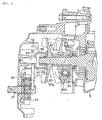
- FIG. 1 is a sectional view of the engine 200 showing a structure of the starter/generator apparatus and is a sectional view taken along line A-A of FIG. 10.
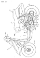
- a crankshaft 12 supported for rotation by main bearings 10, 11 is provided on the swing unit case 31 which includes the hanger 37 held by the main pipe 7 described above, and a connecting rod 14 is connected to the crankshaft 12 by a crank pin 13.
- An inner rotor 15 of the starter/generator apparatus is provided at one end portion of the crankshaft 12 which extends from a crank chamber 9.
- the inner rotor 15 includes a rotor boss 16 and permanent magnets 19 fitted on an outer periphery of the rotor boss 16.
- the permanent magnets 19 are, for example, neodymium-iron-boron type magnets and are provided at six locations at equal angular distances around the rotor boss 16.
- the rotor boss 16 is fitted at a central portion thereof with a tapering portion of an end of the crankshaft 12.
- a flange member 39 is disposed at an end of the rotor boss 16 (end on the opposite side to the crankshaft 12), and the rotor boss 16 is secured to the crankshaft 12 together with the flange member 39 by a bolt 20.
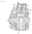
- a radiator fan 57 is mounted on the flange member 39, and a radiator 58 is provided in an opposing relationship to the radiator fan 57. Further, a sprocket wheel 59 is secured to the crankshaft 12 between the inner rotor 15 and the main bearing 11, and a chain 60 for acquiring power for driving a camshaft (refer to FIG. 2) from the crankshaft 12 is wrapped around the sprocket wheel 59. It is to be noted that the sprocket wheel 59 is formed integrally with a gear wheel 61 for transmitting power to a pump which circulates lubricating oil. The gear wheel 61 transmits power to another gear wheel secured to a drive shaft for a gear pump which is hereinafter described with reference to FIG. 7.
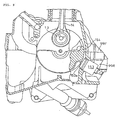
- crankshaft 12 is rotated, thereby allowing starting of the engine 200.
- the kicking down of the kick pedal 29 is reduced so that the sector helical gear 91 is rotated reversely by the return springs 92, 93, then the engagement between the driving dog gear wheel 90 and the driven dog gear wheel 86 is cancelled.
Landscapes
- Engineering & Computer Science (AREA)
- Power Engineering (AREA)
- Chemical & Material Sciences (AREA)
- Combustion & Propulsion (AREA)
- Mechanical Engineering (AREA)
- General Engineering & Computer Science (AREA)
- Connection Of Motors, Electrical Generators, Mechanical Devices, And The Like (AREA)
- Lubrication Of Internal Combustion Engines (AREA)
- Permanent Magnet Type Synchronous Machine (AREA)
- Dc Machiner (AREA)
Claims (5)
- Verbrennungsmaschine mit einer Kurbelwelle (12), einem Zylinderkopf (32) und einer Anlasser/Generatorvorrichtung, umfassend:dadurch gekennzeichnet, dass die Maschine eine Viertakt-Verbrennungsmaschine mit einem Ventilantriebssystem (60, 69, 72, 69) zum Antreiben eines Einlassventils (95) und eines Auslassventils (96) ist, welche an dem Zylinderkopf (32) vorgesehen sind, und mit einem Antriebsmittel (59) für das Ventilantriebssystem, welches auf einer Seite der Kurbelwelle (12) angeordnet ist, wobei der innere Rotor (15) an einem Endabschnitt der Kurbelwelle (12) auf der Seite vorgesehen ist, auf welcher das Antriebsmittel (59) vorgesehen ist, wobei das Reglermittel (54) an dem inneren Rotor (15) auf der Seite vorgesehen ist, welche dem Antriebsmittel (59) benachbart ist, und wobei ein Flanschelement (39) an einem axialen Ende eines Rotorvorsprungs (16) auf der der Kurbelwelle (12) gegenüberliegenden Seite derart angeordnet ist, dass ein Abschnitt des Rotorvorsprungs (16), welcher an einer Schraube (20) anliegt, und ein zylindrischer Abschnitt (40) des Rotorvorsprungs (16), welcher den Bürstenhalter (41) lagert, axial zwischen der Kurbelwelle (12) und dem Flanschelement (39) angeordnet sind, wobei der Rotorvorsprung (16) und das Flanschelement (39) durch die Schraube (20) gemeinsam an der Kurbelwelle (12) befestigt sind, wobei das Flanschelement (39) axial zwischen dem Rotorvorsprung (16) und dem Kopf der Schraube (20) angeordnet ist.einen inneren Rotor (15), welcher an der Kurbelwelle (12) vorgesehen ist und einen Permanentmagneten (19) aufweist, der an einem Umfang desselben angeordnet ist;einen äußeren Stator (47), welcher um einen Außenumfang des inneren Rotors (15) herum angeordnet ist;eine Anlasserspule (51) und eine Generatorspule (50), welche auf den äußeren Stator (47) gewickelt sind,ein Reglermittel (54), welches an dem inneren Rotor (15) auf der Seite vorgesehen ist, die zu einer Kurbel der Kurbelwelle (12) hinweist,ein Bürstenzufuhrmittel (41, 44) für die Anlasserspule, welches an dem inneren Rotor (15) für eine Verlagerung in eine axiale Richtung des inneren Rotors (15) auf der Seite vorgesehen ist, die der Seite gegenüber liegt, auf welcher das Reglermittel (54) vorgesehen ist, undein Verbindungsmittel (45) zum Verbinden des Reglermittels (54) und des Bürstenzufuhrmittels (41, 44) miteinander, um das Bürstenzufuhrmittel (41, 44) in Kontakt mit der Zufuhrseite zu bringen und diesen Kontakt wieder zu lösen,
- Verbrennungsmaschine nach Anspruch 1,
dadurch gekennzeichnet, dass
der zylindrische Abschnitt (40) zu der Seite des Flanschelements (39) vorragt, wobei der Bürstenhalter (41) als ein Teil der Bürstenzufuhrmittel (41, 44) an einem Außenumfang des zylindrischen Abschnitts (40) vorgesehen ist, wobei er dazu ausgebildet ist, auf dem zylindrischen Abschnitt (40) zu gleiten. - Verbrennungsmaschine nach Anspruch 1 oder 2,
dadurch gekennzeichnet, dass
das Reglermittel (54) eine Tasche (56) zur Aufnahme eines Reglergewichts (55) darin umfasst, wobei die Tasche (56) einen sich verjüngenden Querschnitt aufweist, welcher an der radial äußeren Seite konkav ist, wobei der sich verjüngende Querschnitt durch eine Taschenwand vorgesehen ist, welche integral an dem Rotorvorsprung (16) ausgebildet ist. - Verbrennungsmaschine nach Anspruch 3,
dadurch gekennzeichnet, dass
das Reglermittel (54) eine Platte (46) umfasst, welche in einer axialen Richtung verlagerbar ist, wobei die Verlagerung der Platte (46) ein Verlagern eines Bürstenhalters (41) als ein Teil der Bürstenzufuhrmittel (41, 44) bewirkt. - Verbrennungsmaschine nach Anspruch 4,
dadurch gekennzeichnet, dass
die Platte (46) eine ebene Platte ist.
Applications Claiming Priority (2)
| Application Number | Priority Date | Filing Date | Title |
|---|---|---|---|
| JP11079337A JP2000278926A (ja) | 1999-03-24 | 1999-03-24 | 4サイクル内燃機関用始動兼発電装置 |
| JP7933799 | 1999-03-24 |
Related Child Applications (1)
| Application Number | Title | Priority Date | Filing Date |
|---|---|---|---|
| EP05012041.9 Division-Into | 2005-06-03 |
Publications (3)
| Publication Number | Publication Date |
|---|---|
| EP1039619A2 EP1039619A2 (de) | 2000-09-27 |
| EP1039619A3 EP1039619A3 (de) | 2003-03-19 |
| EP1039619B1 true EP1039619B1 (de) | 2005-12-14 |
Family
ID=13687096
Family Applications (1)
| Application Number | Title | Priority Date | Filing Date |
|---|---|---|---|
| EP00105496A Expired - Lifetime EP1039619B1 (de) | 1999-03-24 | 2000-03-15 | Anlasser/Generator für eine Viertaktbrennkraftmaschine |
Country Status (7)
| Country | Link |
|---|---|
| EP (1) | EP1039619B1 (de) |
| JP (1) | JP2000278926A (de) |
| KR (1) | KR100362731B1 (de) |
| CN (1) | CN1153337C (de) |
| DE (1) | DE60024702T2 (de) |
| ES (1) | ES2254061T3 (de) |
| TW (1) | TW497320B (de) |
Families Citing this family (12)
| Publication number | Priority date | Publication date | Assignee | Title |
|---|---|---|---|---|
| JP3967552B2 (ja) * | 2001-02-19 | 2007-08-29 | 本田技研工業株式会社 | エンジン用気液分離装置 |
| US20030020337A1 (en) * | 2001-07-26 | 2003-01-30 | Joachim Jon B. | Electric machine rotor with crankshaft torsional damper |
| CN100417009C (zh) * | 2006-07-14 | 2008-09-03 | 李祥盛 | 自控调速电机 |
| CN101795031B (zh) * | 2010-03-23 | 2013-01-09 | 杨荷 | 一种用于电动车的永磁无刷变速电机及方法 |
| CN103166410B (zh) * | 2011-12-12 | 2016-10-05 | 德昌电机(深圳)有限公司 | 有刷电机及风扇装置 |
| WO2014135199A1 (de) * | 2013-03-05 | 2014-09-12 | Siemens Aktiengesellschaft | Verbrennungskraftmaschine mit elektrischem antrieb an der kurbelwelle |
| US20140346780A1 (en) * | 2013-05-21 | 2014-11-27 | Progress Rail Services Corporation | Connection assembly for a power system |
| CN106194539B (zh) * | 2016-07-25 | 2019-04-26 | 潍柴动力股份有限公司 | 一种动力装置 |
| CN107947462B (zh) * | 2017-11-28 | 2024-09-17 | 浙江力俭新能源科技有限公司 | 一种起动发电机 |
| KR102051439B1 (ko) * | 2018-06-28 | 2019-12-03 | 지엠 글로벌 테크놀러지 오퍼레이션스 엘엘씨 | 차량용 엔진의 알터네이터 일체형 캠축 구조체 |
| CN111030385A (zh) * | 2019-12-31 | 2020-04-17 | 宁波仁山电器有限公司 | 厨余垃圾处理器电机的正反转控制装置 |
| CN115864732B (zh) * | 2023-01-05 | 2023-08-04 | 宁波意卡德电器科技有限公司 | 一种新型工业冷风机电机 |
Family Cites Families (12)
| Publication number | Priority date | Publication date | Assignee | Title |
|---|---|---|---|---|
| US1586184A (en) * | 1924-04-17 | 1926-05-25 | Wagner Electric Corp | Dynamo-electric machine |
| US1736662A (en) * | 1925-08-31 | 1929-11-19 | Munz Friedrich | Appliance for internal-combustion engines |
| GB645085A (en) * | 1947-10-01 | 1950-10-25 | Leland Electric Co | Improvements in or relating to a brush lifting mechanism |
| US3014142A (en) * | 1958-02-06 | 1961-12-19 | Lee Royal | Synchronous dynamo-electric machines |
| DE1931582A1 (de) * | 1969-06-21 | 1971-01-07 | Bosch Gmbh Robert | Schubschraubtrieb fuer Andrehmotoren von Brennkraftmaschinen |
| DE2448069A1 (de) * | 1974-10-09 | 1976-04-22 | Bosch Gmbh Robert | Andrehvorrichtung fuer brennkraftmaschinen |
| GB1523467A (en) * | 1975-11-06 | 1978-08-31 | Plessey Co Ltd | Rotary electric machines |
| US4219739A (en) * | 1978-04-27 | 1980-08-26 | Lear Avia Corporation | Starter motor-alternator apparatus |
| JPS6258858A (ja) * | 1985-09-02 | 1987-03-14 | Honda Motor Co Ltd | 車両用発電装置 |
| JP3351042B2 (ja) * | 1993-09-02 | 2002-11-25 | 株式会社デンソー | 車両用内燃機関始動装置 |
| JP3792282B2 (ja) * | 1995-02-17 | 2006-07-05 | 本田技研工業株式会社 | 車両用始動兼発電装置 |
| JP3649301B2 (ja) * | 1996-01-30 | 2005-05-18 | 本田技研工業株式会社 | 2サイクル内燃機関における始動兼発電装置 |
-
1999
- 1999-03-24 JP JP11079337A patent/JP2000278926A/ja active Pending
-
2000
- 2000-03-02 TW TW089103696A patent/TW497320B/zh not_active IP Right Cessation
- 2000-03-10 KR KR1020000012045A patent/KR100362731B1/ko not_active Expired - Fee Related
- 2000-03-13 CN CNB001040243A patent/CN1153337C/zh not_active Expired - Fee Related
- 2000-03-15 ES ES00105496T patent/ES2254061T3/es not_active Expired - Lifetime
- 2000-03-15 DE DE60024702T patent/DE60024702T2/de not_active Expired - Fee Related
- 2000-03-15 EP EP00105496A patent/EP1039619B1/de not_active Expired - Lifetime
Also Published As
| Publication number | Publication date |
|---|---|
| CN1153337C (zh) | 2004-06-09 |
| CN1268799A (zh) | 2000-10-04 |
| TW497320B (en) | 2002-08-01 |
| EP1039619A2 (de) | 2000-09-27 |
| KR20000062823A (ko) | 2000-10-25 |
| DE60024702D1 (de) | 2006-01-19 |
| JP2000278926A (ja) | 2000-10-06 |
| EP1039619A3 (de) | 2003-03-19 |
| KR100362731B1 (ko) | 2002-11-27 |
| DE60024702T2 (de) | 2006-07-13 |
| ES2254061T3 (es) | 2006-06-16 |
Similar Documents
| Publication | Publication Date | Title |
|---|---|---|
| EP1039619B1 (de) | Anlasser/Generator für eine Viertaktbrennkraftmaschine | |
| US20030140881A1 (en) | Engine starting control apparatus | |
| KR100385850B1 (ko) | 엔진 시동장치 | |
| JP4117816B2 (ja) | 車両用始動兼発電装置 | |
| CN101598099A (zh) | 发动机的蓄力式起动系统 | |
| JP2000352327A5 (de) | ||
| JPH10148142A (ja) | 車両の始動制御装置 | |
| JP2000352329A5 (de) | ||
| KR100347859B1 (ko) | 자동이륜차 | |
| JP5047746B2 (ja) | 小型車両のパワーユニット | |
| JP2000103384A (ja) | ハイブリッド式パワーユニット付車両 | |
| US6336434B1 (en) | Engine unit of outboard motor | |
| JPH04203226A (ja) | 自動二輪車の駆動装置 | |
| JP4640830B2 (ja) | 内燃機関の始動装置 | |
| JP4125429B2 (ja) | 自動二輪車 | |
| US7210851B2 (en) | Arrangement structure of bearings | |
| KR100216394B1 (ko) | 4싸이클 내연기관의 크랭크 케이스구조 | |
| JP4825324B2 (ja) | 駆動装置 | |
| JP4141044B2 (ja) | エンジン始動装置 | |
| JP7383675B2 (ja) | 内燃機関のacgカバー | |
| JP2008045562A (ja) | 自動二輪車 | |
| JPH0610428B2 (ja) | V型内燃機関のガバナ装置 | |
| JP2001180563A (ja) | ユニットスイング式エンジンの伝動装置 | |
| JPH08151927A (ja) | 単気筒2サイクルエンジン | |
| JP2000097136A (ja) | エンジンの始動兼発電装置 |
Legal Events
| Date | Code | Title | Description |
|---|---|---|---|
| PUAI | Public reference made under article 153(3) epc to a published international application that has entered the european phase |
Free format text: ORIGINAL CODE: 0009012 |
|
| AK | Designated contracting states |
Kind code of ref document: A2 Designated state(s): AT BE CH CY DE DK ES FI FR GB GR IE IT LI LU MC NL PT SE |
|
| AX | Request for extension of the european patent |
Free format text: AL;LT;LV;MK;RO;SI |
|
| PUAL | Search report despatched |
Free format text: ORIGINAL CODE: 0009013 |
|
| AK | Designated contracting states |
Kind code of ref document: A3 Designated state(s): AT BE CH CY DE DK ES FI FR GB GR IE IT LI LU MC NL PT SE Designated state(s): AT BE CH CY DE DK ES FI FR GB GR IE IT LI LU MC NL PT SE |
|
| AX | Request for extension of the european patent |
Extension state: AL LT LV MK RO SI |
|
| RIC1 | Information provided on ipc code assigned before grant |
Ipc: 7H 02K 23/68 B Ipc: 7H 02K 23/62 B Ipc: 7H 02K 7/118 B Ipc: 7H 02K 7/10 B Ipc: 7H 02K 7/18 B Ipc: 7H 02K 23/52 A |
|
| 17P | Request for examination filed |
Effective date: 20030604 |
|
| 17Q | First examination report despatched |
Effective date: 20030718 |
|
| AKX | Designation fees paid |
Designated state(s): DE ES FR IT |
|
| GRAP | Despatch of communication of intention to grant a patent |
Free format text: ORIGINAL CODE: EPIDOSNIGR1 |
|
| GRAS | Grant fee paid |
Free format text: ORIGINAL CODE: EPIDOSNIGR3 |
|
| GRAA | (expected) grant |
Free format text: ORIGINAL CODE: 0009210 |
|
| AK | Designated contracting states |
Kind code of ref document: B1 Designated state(s): DE ES FR IT |
|
| REF | Corresponds to: |
Ref document number: 60024702 Country of ref document: DE Date of ref document: 20060119 Kind code of ref document: P |
|
| REG | Reference to a national code |
Ref country code: ES Ref legal event code: FG2A Ref document number: 2254061 Country of ref document: ES Kind code of ref document: T3 |
|
| ET | Fr: translation filed | ||
| PLBE | No opposition filed within time limit |
Free format text: ORIGINAL CODE: 0009261 |
|
| STAA | Information on the status of an ep patent application or granted ep patent |
Free format text: STATUS: NO OPPOSITION FILED WITHIN TIME LIMIT |
|
| 26N | No opposition filed |
Effective date: 20060915 |
|
| PGFP | Annual fee paid to national office [announced via postgrant information from national office to epo] |
Ref country code: DE Payment date: 20070308 Year of fee payment: 8 |
|
| PGFP | Annual fee paid to national office [announced via postgrant information from national office to epo] |
Ref country code: ES Payment date: 20070417 Year of fee payment: 8 |
|
| PGFP | Annual fee paid to national office [announced via postgrant information from national office to epo] |
Ref country code: IT Payment date: 20070519 Year of fee payment: 8 |
|
| PGFP | Annual fee paid to national office [announced via postgrant information from national office to epo] |
Ref country code: FR Payment date: 20070308 Year of fee payment: 8 |
|
| REG | Reference to a national code |
Ref country code: FR Ref legal event code: ST Effective date: 20081125 |
|
| PG25 | Lapsed in a contracting state [announced via postgrant information from national office to epo] |
Ref country code: DE Free format text: LAPSE BECAUSE OF NON-PAYMENT OF DUE FEES Effective date: 20081001 |
|
| PG25 | Lapsed in a contracting state [announced via postgrant information from national office to epo] |
Ref country code: FR Free format text: LAPSE BECAUSE OF NON-PAYMENT OF DUE FEES Effective date: 20080331 |
|
| REG | Reference to a national code |
Ref country code: ES Ref legal event code: FD2A Effective date: 20080317 |
|
| PG25 | Lapsed in a contracting state [announced via postgrant information from national office to epo] |
Ref country code: ES Free format text: LAPSE BECAUSE OF NON-PAYMENT OF DUE FEES Effective date: 20080317 |
|
| PG25 | Lapsed in a contracting state [announced via postgrant information from national office to epo] |
Ref country code: IT Free format text: LAPSE BECAUSE OF NON-PAYMENT OF DUE FEES Effective date: 20080315 |