EP1036618A2 - Cermetwerkzeug uund dessen Herstelungsmethode - Google Patents
Cermetwerkzeug uund dessen Herstelungsmethode Download PDFInfo
- Publication number
- EP1036618A2 EP1036618A2 EP00301497A EP00301497A EP1036618A2 EP 1036618 A2 EP1036618 A2 EP 1036618A2 EP 00301497 A EP00301497 A EP 00301497A EP 00301497 A EP00301497 A EP 00301497A EP 1036618 A2 EP1036618 A2 EP 1036618A2
- Authority
- EP
- European Patent Office
- Prior art keywords
- tool
- cermet
- phase
- hard layer
- bonding
- Prior art date
- Legal status (The legal status is an assumption and is not a legal conclusion. Google has not performed a legal analysis and makes no representation as to the accuracy of the status listed.)
- Withdrawn
Links
Images


Classifications
-
- C—CHEMISTRY; METALLURGY
- C22—METALLURGY; FERROUS OR NON-FERROUS ALLOYS; TREATMENT OF ALLOYS OR NON-FERROUS METALS
- C22C—ALLOYS
- C22C29/00—Alloys based on carbides, oxides, nitrides, borides, or silicides, e.g. cermets, or other metal compounds, e.g. oxynitrides, sulfides
- C22C29/02—Alloys based on carbides, oxides, nitrides, borides, or silicides, e.g. cermets, or other metal compounds, e.g. oxynitrides, sulfides based on carbides or carbonitrides
-
- B—PERFORMING OPERATIONS; TRANSPORTING
- B22—CASTING; POWDER METALLURGY
- B22F—WORKING METALLIC POWDER; MANUFACTURE OF ARTICLES FROM METALLIC POWDER; MAKING METALLIC POWDER; APPARATUS OR DEVICES SPECIALLY ADAPTED FOR METALLIC POWDER
- B22F7/00—Manufacture of composite layers, workpieces, or articles, comprising metallic powder, by sintering the powder, with or without compacting wherein at least one part is obtained by sintering or compression
- B22F7/06—Manufacture of composite layers, workpieces, or articles, comprising metallic powder, by sintering the powder, with or without compacting wherein at least one part is obtained by sintering or compression of composite workpieces or articles from parts, e.g. to form tipped tools
-
- B—PERFORMING OPERATIONS; TRANSPORTING
- B23—MACHINE TOOLS; METAL-WORKING NOT OTHERWISE PROVIDED FOR
- B23B—TURNING; BORING
- B23B27/00—Tools for turning or boring machines; Tools of a similar kind in general; Accessories therefor
- B23B27/14—Cutting tools of which the bits or tips or cutting inserts are of special material
- B23B27/141—Specially shaped plate-like cutting inserts, i.e. length greater or equal to width, width greater than or equal to thickness
- B23B27/145—Specially shaped plate-like cutting inserts, i.e. length greater or equal to width, width greater than or equal to thickness characterised by having a special shape
-
- B—PERFORMING OPERATIONS; TRANSPORTING
- B22—CASTING; POWDER METALLURGY
- B22F—WORKING METALLIC POWDER; MANUFACTURE OF ARTICLES FROM METALLIC POWDER; MAKING METALLIC POWDER; APPARATUS OR DEVICES SPECIALLY ADAPTED FOR METALLIC POWDER
- B22F5/00—Manufacture of workpieces or articles from metallic powder characterised by the special shape of the product
- B22F2005/001—Cutting tools, earth boring or grinding tool other than table ware
-
- B—PERFORMING OPERATIONS; TRANSPORTING
- B22—CASTING; POWDER METALLURGY
- B22F—WORKING METALLIC POWDER; MANUFACTURE OF ARTICLES FROM METALLIC POWDER; MAKING METALLIC POWDER; APPARATUS OR DEVICES SPECIALLY ADAPTED FOR METALLIC POWDER
- B22F2998/00—Supplementary information concerning processes or compositions relating to powder metallurgy
-
- B—PERFORMING OPERATIONS; TRANSPORTING
- B23—MACHINE TOOLS; METAL-WORKING NOT OTHERWISE PROVIDED FOR
- B23B—TURNING; BORING
- B23B2200/00—Details of cutting inserts
- B23B2200/24—Cross section of the cutting edge
- B23B2200/242—Cross section of the cutting edge bevelled or chamfered
-
- B—PERFORMING OPERATIONS; TRANSPORTING
- B23—MACHINE TOOLS; METAL-WORKING NOT OTHERWISE PROVIDED FOR
- B23B—TURNING; BORING
- B23B2200/00—Details of cutting inserts
- B23B2200/24—Cross section of the cutting edge
- B23B2200/245—Cross section of the cutting edge rounded
-
- B—PERFORMING OPERATIONS; TRANSPORTING
- B23—MACHINE TOOLS; METAL-WORKING NOT OTHERWISE PROVIDED FOR
- B23B—TURNING; BORING
- B23B2222/00—Materials of tools or workpieces composed of metals, alloys or metal matrices
- B23B2222/16—Cermet
-
- Y—GENERAL TAGGING OF NEW TECHNOLOGICAL DEVELOPMENTS; GENERAL TAGGING OF CROSS-SECTIONAL TECHNOLOGIES SPANNING OVER SEVERAL SECTIONS OF THE IPC; TECHNICAL SUBJECTS COVERED BY FORMER USPC CROSS-REFERENCE ART COLLECTIONS [XRACs] AND DIGESTS
- Y10—TECHNICAL SUBJECTS COVERED BY FORMER USPC
- Y10T—TECHNICAL SUBJECTS COVERED BY FORMER US CLASSIFICATION
- Y10T428/00—Stock material or miscellaneous articles
- Y10T428/24—Structurally defined web or sheet [e.g., overall dimension, etc.]
- Y10T428/24802—Discontinuous or differential coating, impregnation or bond [e.g., artwork, printing, retouched photograph, etc.]
-
- Y—GENERAL TAGGING OF NEW TECHNOLOGICAL DEVELOPMENTS; GENERAL TAGGING OF CROSS-SECTIONAL TECHNOLOGIES SPANNING OVER SEVERAL SECTIONS OF THE IPC; TECHNICAL SUBJECTS COVERED BY FORMER USPC CROSS-REFERENCE ART COLLECTIONS [XRACs] AND DIGESTS
- Y10—TECHNICAL SUBJECTS COVERED BY FORMER USPC
- Y10T—TECHNICAL SUBJECTS COVERED BY FORMER US CLASSIFICATION
- Y10T428/00—Stock material or miscellaneous articles
- Y10T428/24—Structurally defined web or sheet [e.g., overall dimension, etc.]
- Y10T428/24942—Structurally defined web or sheet [e.g., overall dimension, etc.] including components having same physical characteristic in differing degree
-
- Y—GENERAL TAGGING OF NEW TECHNOLOGICAL DEVELOPMENTS; GENERAL TAGGING OF CROSS-SECTIONAL TECHNOLOGIES SPANNING OVER SEVERAL SECTIONS OF THE IPC; TECHNICAL SUBJECTS COVERED BY FORMER USPC CROSS-REFERENCE ART COLLECTIONS [XRACs] AND DIGESTS
- Y10—TECHNICAL SUBJECTS COVERED BY FORMER USPC
- Y10T—TECHNICAL SUBJECTS COVERED BY FORMER US CLASSIFICATION
- Y10T428/00—Stock material or miscellaneous articles
- Y10T428/26—Web or sheet containing structurally defined element or component, the element or component having a specified physical dimension
- Y10T428/263—Coating layer not in excess of 5 mils thick or equivalent
- Y10T428/264—Up to 3 mils
- Y10T428/265—1 mil or less
Definitions
- the present invention relates to a cermet tool capable of, for example, cutting steel at high speed, and to a method for manufacturing the same.
- Cermet is a sintered hard alloy made of a bonding-phase metal of the iron group, such as Ni, and a hard-phase material, such as TiCN.
- a sintered skin which has been formed during sintering may remain on the surface of a cermet tool of this type.
- exudation sometimes called precipitation
- a bonding-phase metal such as Ni
- the exuded bonding-phase metal and a workpiece material often fuse together, thereby imposing excessive cutting resistance on the cutting edge of the tool with resultant chipping of the cutting edge.
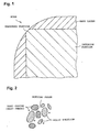
- a hard layer P2 harder than an interior portion P1 of a cermet tool is formed on the surface of the tool (the composition of the hard layer P2 differs from that of the interior portion P1).
- the amount of a bonding-phase metal contained in the hard layer P2 is less than that contained in the interior portion P1 of the tool (i.e., the hard layer P2 has a higher hard-phase material content). Through formation of such a hard layer P2 on the surface of the tool, resistance of the tool to wear and chipping is improved.
- the coefficient of thermal expansion of the bonding-phase metal such as Ni
- the hard-phase material such as TiCN
- the present invention has been conceived in view of the above problems, and an object of the present invention is to provide a cermet tool having excellent resistance to chipping and wear as well as to provide a method for manufacturing the same.
- a cermet tool comprising a hard layer formed on a surface thereof, characterized in that an exposure portion is formed at a nose so as to expose an interior portion of the tool and in that the hard layer is disposed around the exposure portion.
- FIG. 1 shows a cermet tool assuming substantially the form of a rectangular parallelepiped (negative tip) as viewed from above the rake face, in which the hard layer located on the rake-face side is removed.
- the exposure portion which is softer than the hard layer and has toughness, is brought into contact with the workpiece. Therefore, even when a large force is imposed on the nose, the nose is less likely to chip.
- the exposure portion is surrounded by the hard layer, which is harder than the interior portion of the tool. Therefore, even when cutting-chips hit the hard layer during cutting, the hard layer does not wear significantly.
- the cermet tool of the present invention has the exposure portion, where the interior portion of the tool is exposed, and the hard layer (disposed around the radiused portion), the tool exhibits excellent resistance to chipping and wear.
- the term "cermet” means a sintered hard alloy comprising at least a hard-phase material such as TiCN, and a bonding-phase metal of the iron family such as Ni; and the term “cermet tool” means a tool formed of such an alloy.
- the exposure portion is a radiused portion or rather circular arc or a chamfered portion formed such that an interior portion of the tool is exposed, preferably the exposure portion is formed at a comer portion (nose) of the tool.
- the radius of the radiused portion is 0.04 mm to 0.16 mm.
- the radiused portion can be exposed appropriately through polishing of the nose.
- the nose is less likely to chip during cutting, thereby enabling favorable cutting.
- the thickness of the hard layer is 2 ⁇ m to 20 ⁇ m.
- the hard layer is appropriately disposed around the radiused portion when the radiused portion is to be exposed through polishing of the nose.
- the nose becomes less likely to wear during cutting, thereby enabling favorable cutting.
- the hard layer When the thickness of the hard layer is not less than 2 ⁇ m, the hard layer provides a sufficient wear resistance effect. When the thickness of the hard layer is not greater than 20 ⁇ m, the radiused portion can be easily exposed through radiusing in a conventionally employed range.
- the radiused portion when the radius of the radiused portion is 0.04 mm to 0.16 mm and the thickness of the hard layer is 2 ⁇ m to 20 ⁇ m, the radiused portion can be readily formed at the nose through radiusing such that the interior portion of the tool is exposed to an appropriate extent.
- the tool contains as a bonding phase at least two iron-group metals and contains as a hard phase at least two members selected from the group consisting of carbides, nitrides, and carbonitrides of elements in Groups 4A, 5A, and 6A of the periodic table.
- a cermet tool comprises a hard phase which contains hard grains, such as TiCN; a bonding phase composed of bonding-phase metals and a binder; and a solid solution composed of bonding-phase and hard-phase components.
- the present invention specifies advantageous compositions of the cermet tool.
- iron-group metals examples include Ni, Co, and Fe.
- Examples of carbides, nitrides, and carbonitrides of elements in Groups 4A, 5A, and 6A include TiC, which is a carbide of a Group 4A element; TiN, which is a nitride of a Group 4A element; TiCN, which is a carbonitride of a Group 4A element; VC, NbC, and TaC, which are carbides of Group 5A elements; and Mo 2 C and WC, which are carbides of Group 6A elements.
- a degree which corresponds to substantially no exudation of bonding-phase metals being observed may be equivalent, for example, to a bonding-phase-metal content of not greater than 1.9% by weight as measured by means of an SEM (an energy dispersive X-ray analyzer attached to a scanning electron microscope). Since measurement of a bonding-phase-metal content by means of the SEM covers not only the surface of the sintered skin but also a small distance into the interior portion of the skin, the bonding-phase-metal content of not greater than 1.9% by weight may be considered to indicate substantially no exudation of bonding-phase metals being observed.
- SEM an energy dispersive X-ray analyzer attached to a scanning electron microscope
- the amount of bonding-phase metals as measured substantially at a center of the interior portion of the tool is taken as 100% by weight
- the amount of bonding-phase metals contained in the hard layer is not greater than 11% by weight.
- the hard layer can be defined by the amount of bonding-phase metals contained in the hard layer.
- the bonding-phase-metal content of the hard layer being not greater than 11% by weight means that the amount of bonding-phase metals which are present in the vicinity of the surface of the sintered skin and which are to be potentially exuded into the sintered skin is small. Thus, fusion is less likely to occur, thereby imparting excellent resistance to chipping.
- a center of the interior portion of the tool is a position where the amount of bonding-phase metals is measured for use as a reference in compositional comparison, since variation in composition at such a portion is small.
- a sintered skin is present on a flank and/or rake face of the cermet tool.
- the invention also provides a method for manufacturing a cermet tool, characterized by comprising: sintering a cermet material compact; and lowering the temperature of a resultant sintered body under a reduced pressure, preferably in the range of from 5 Torr to 50 Torr, in a nitrogen atmosphere for 15 to 25 minutes.
- a pressure of 1 Torr is understood to be approximately 130 Pa.
- the amount of bonding-phase metals contained in the hard layer can be reduced (to, for example, not greater than 11% by weight) to thereby suppress exudation of bonding-phase metals into the sintered skin.
- the method of the present invention specifies nitrogen as an atmospheric gas for use in cooling, for the following reason.
- nitrogen gas for example, 4A-, 5A-, and 6A-group components of the surface of the tool are nitrided to thereby form a nitriding phase composed of nitrides of 4A-, 5A-, and 6A-group components.
- the nitriding phase shows poor wettability to bonding-phase metal components, so that exudation of bonding-phase metals into the surface of a sintered body is suppressed.
- a temperature-lowering time of 15 to 25 minutes is employed for the following reason.
- the temperature-lowering time is less than 15 minutes, the effect of suppressing exudation of bonding-phase metals becomes insufficient.
- the temperature-lowering time is in excess of 25 minutes, a graphite phase is formed.
- the compact is sintered at a temperature of 1400°C to 1600°C in a pressure-reduced atmosphere (for example, in an inert gas other than nitrogen), sufficient sintering occurs.
- the method for manufacturing a cermet tool is further characterized in that the partial pressure of nitrogen in the pressure-reduced nitrogen atmosphere is 5 Torr to 50 Torr.
- the partial pressure of nitrogen is limited to 5 Torr to 50 Torr for the following reason.
- the partial pressure of nitrogen is not higher than 5 Torr, the effect of suppressing exudation of bonding-phase metals becomes insufficient.
- the partial pressure of nitrogen is not lower than 50 Torr, excess carbon generated through nitriding of, for example, 4A-, 5A-, and 6A-group components forms a graphite phase, causing an impairment in physical properties (such as strength).
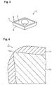
- a cermet tool 1 is a cermet tip assuming a shape which complies with ISO DCMT070204.
- the cermet tool 1 has a thickness of 2.38 mm. Each side (cutting edge) of a rake face 3, which is an upper face in FIG. 3, has a length of 6.88 mm.
- the cermet tool 1 assumes a substantially rhombic plan view such that the rhombic size reduces downward in FIG. 3.
- a nose 7 located at a corner of the cermet tool 1 has an acute angle (as viewed from the flank side; for example, 83°); i.e., the cermet tool 1 is a positive-type cermet tip.
- the upper face (rake face) 3 and all side faces (flanks) 9 of the cermet tool 1 assume the form of sintered skin.
- the cermet tool 1 includes a hard layer 11 which is very hard and covers the surface of the tool 1, and an interior portion 13 which is covered with and softer than the hard layer 11.
- FIG. 4 is a view of the cermet tool 1 as viewed from the side of the rake face 3, while the hard layer 11 of the rake face 3 is removed.
- the hard layer 11 has a thickness of 2 ⁇ m to 20 ⁇ m and contains hard-phase components, such as TiCN, and bonding-phase metals, such as Fe and Ni.
- the bonding-phase metals are contained in the hard layer 11 in an amount of as small as not greater than 11% by weight.
- the sintered skin of the surface of the hard layer 11 is substantially free of exudation of bonding-phase metals.
- the interior portion 13 of the tool contains hard-phase components, such as TiCN, and bonding-phase metals.
- the hard-phase component content is lower than that of the hard layer 11, and the bonding-phase-metal content is higher than that of the hard layer 11.
- the interior portion 13 is softer than the hard layer 11.
- the tip of the nose 7 is radiused through honing to curvature having a radius of 0.04 mm to 0.16 mm so as to form a radiused portion 15 where the interior portion 13 of the tool is exposed. Accordingly, the hard layer 11 is disposed around the radiused portion (exposure portion) 15.
- the hard layer 11 around the exposure portion is also radiused.
- the portion at which the interior portion 13 of the tool is exposed through radiusing is referred to as a "radiused portion.”
- cermet sintered-bodies (samples A to E), which serve as example cermet tools of the present invention.
- Example 1 1500 30 20 2 1550 20 15 3 1600 10 15 4 1400 50 20 5 1450 5 25 Comparative example 6 1500 Furnace cooling in Ar atmosphere 7 1550 Furnace cooling in Ar atmosphere 8 1600 Furnace cooling in Ar atmosphere 9 1400 Furnace cooling in Ar atmosphere 10 1450 Furnace cooling in Ar atmosphere
- Each of the cermet sintered-bodies was cut at a central portion.
- the cut surface was mirror-polished and was then examined for the amount of bonding-phase metals contained in a central portion and for the amount of bonding-phase metals contained in the hard layer formed in the vicinity of the sintered skin, by means of the energy dispersive X-ray analyzer attached to the scanning electron microscope.
- the thickness of the hard layer was examined by means of observation through the scanning electron microscope.
- Figs. 5 and 6 show the images of the section of the cermet sintered-body of the present invention photographed by means of SEM and the images of the surface of the cermet sintered-body of the present invention photographed by means of SEM.
- Fig. 5(a) shows the image of the section of a central portion of sample No. 1 photographed at 5000 times magnificatios by means of SEM
- Fig. 5(b) shows the image of the section of a portion of sample No. 1 including the hard layer, photographed at 2000 times magnification by means of SEM
- Fig. 6(a) shows the image of the sintered skin of sample No. 1 photographed at 2000 magnifications by means of SEM.
- FIG. 6(b) shows the image of the sintered skin of sample No. 6, which is a comparative example representing the prior art, photographed at 2000 magnifications by means of SEM.
- the hard layer was removed from a honed portion of the nose, thereby forming a radiused portion where an interior portion of the tool is exposed.
- the radiused portion did not involve exposure of an interior portion of the tool.
- flank wear VB is defined as the amount of wear along the flank of the tool tip from the original rake face level at the cutting edge formed at the intersection of the rake face and the flank face, as explained and illustrated in, for example, EP-A-0926110.
- the test results are shown below in Table 3.
- the cermet tools (sample Nos. 1 to 5) according to the present invention are free of chipping derived from fusion, thus exhibiting excellent resistance to chipping. Also, the amount of wear VB is small, indicating excellent wear resistance.
- cermet tools (sample Nos. 6 to 10) serving as comparative examples suffer chipping or exhibit poor wear resistance.
- examples (sample Nos. 1 to 5) of the present invention has a microstructure composed of a bonding phase and a hard phase. Further, a dense hard layer which contains a large amount of hard grains is formed on the surface of the sintered body. Also, no exudation of bonding-phase metals is observed on the surface of the sintered skin, see FIG. 6(a).
- comparative examples show exudation of bonding-phase metals on the surface of the sintered skin, as exemplified in FIG. 6(b) which shows almost the entire surface covered by exuded bonding-phase metal except at a few dark spots or dents.
- a cermet tool 21 according to the present embodiment differs from embodiment 1 in that in place of the radiused portion, a chamfered portion 25 is formed at the nose 23 through chamfering to thereby expose the interior portion 26 of the tool 21, as shown in Fig. 7.
- the chamfered portion 25 is formed by cutting a corner portion to a flat shape such that the slant angle becomes 25°, the flank face 27 is removed by an amount of 0.04 mm, and the rake face 29 is removed by an amount of 0.10 mm.
- the chamfered portion 25 is formed through grinding by use of, for example, a diamond grinding wheel.
- the hard layer 31 around the exposure portion is also chamfered.
- the portion at which the interior portion 26 of the tool is exposed through chamfering is referred to as a "chamfered portion 25."
- the shape of the chamfered portion 25 is generally called "TN chamfer” and is common in the field of cermet tools.
- the present invention is applicable to both of positive-type and negative-type cermet tips.
- the cermet tool of the present invention includes an exposure portion which is formed at a nose and at which an interior portion of the tool is exposed, and a hard layer disposed around the exposure portion, thereby imparting excellent resistance to wear and chipping.
- the method of the present invention for manufacturing a cermet tool involves, after sintering, the step of lowering temperature for 5 min to 25 min in a nitrogen atmosphere under reduced pressure, thereby reducing the amount of bonding-phase metals contained in the hard layer and thus suppressing exudation of bonding-phase metals into the sintered skin.
- the above-mentioned cermet tool having excellent resistance to wear and chipping can be manufactured.
Landscapes
- Engineering & Computer Science (AREA)
- Mechanical Engineering (AREA)
- Chemical & Material Sciences (AREA)
- Materials Engineering (AREA)
- Composite Materials (AREA)
- Manufacturing & Machinery (AREA)
- Metallurgy (AREA)
- Organic Chemistry (AREA)
- Cutting Tools, Boring Holders, And Turrets (AREA)
- Powder Metallurgy (AREA)
Applications Claiming Priority (4)
| Application Number | Priority Date | Filing Date | Title |
|---|---|---|---|
| JP5151699 | 1999-02-26 | ||
| JP5151699 | 1999-02-26 | ||
| JP2000028245A JP2000308907A (ja) | 1999-02-26 | 2000-02-04 | サーメット工具及びその製造方法 |
| JP2000028245 | 2000-02-04 |
Publications (3)
| Publication Number | Publication Date |
|---|---|
| EP1036618A2 true EP1036618A2 (de) | 2000-09-20 |
| EP1036618A3 EP1036618A3 (de) | 2003-07-09 |
| EP1036618A9 EP1036618A9 (de) | 2004-10-06 |
Family
ID=26392062
Family Applications (1)
| Application Number | Title | Priority Date | Filing Date |
|---|---|---|---|
| EP00301497A Withdrawn EP1036618A3 (de) | 1999-02-26 | 2000-02-25 | Cermetwerkzeug uund dessen Herstelungsmethode |
Country Status (4)
| Country | Link |
|---|---|
| US (1) | US6410121B1 (de) |
| EP (1) | EP1036618A3 (de) |
| JP (1) | JP2000308907A (de) |
| KR (1) | KR100654524B1 (de) |
Cited By (1)
| Publication number | Priority date | Publication date | Assignee | Title |
|---|---|---|---|---|
| DE10332101A1 (de) * | 2003-07-15 | 2005-02-03 | Kennametal Inc. | Schneidwerkzeug und Verfahren zur Verringerung der Verschleißmarkenbreite bei einem Schneidwerkzeug |
Families Citing this family (9)
| Publication number | Priority date | Publication date | Assignee | Title |
|---|---|---|---|---|
| JP2004521615A (ja) * | 2000-11-06 | 2004-07-22 | インヴィトロジェン コーポレーション | 乾燥粉末細胞および細胞培養試薬およびその生産の方法 |
| US8178220B2 (en) * | 2004-04-30 | 2012-05-15 | Sumitomo Electric Hardmetal Corp. | Surface-covered cubic boron nitride sintered body tool and method of manufacturing the same |
| EP1944110B1 (de) * | 2007-01-15 | 2012-11-07 | Fraisa Holding AG | Verfahren zur Behandlung und Bearbeitung von Werkzeugen zur spanabhebenden Bearbeitung von Werkstücken |
| JP2010221351A (ja) * | 2009-03-24 | 2010-10-07 | Sumitomo Electric Ind Ltd | 刃先交換型バイト用チップ |
| CN102345092A (zh) * | 2010-07-29 | 2012-02-08 | 鸿富锦精密工业(深圳)有限公司 | 涂层、具有该涂层的被覆件及该被覆件的制备方法 |
| JP6380016B2 (ja) * | 2014-11-05 | 2018-08-29 | 株式会社タンガロイ | サーメット工具および被覆サーメット工具 |
| KR101863057B1 (ko) * | 2015-12-17 | 2018-06-01 | 한국야금 주식회사 | 절삭공구용 인써트 |
| JP6889128B2 (ja) * | 2018-03-20 | 2021-06-18 | 京セラ株式会社 | 工具及びこれを備えた切削工具 |
| JP7037121B2 (ja) * | 2018-09-28 | 2022-03-16 | 三菱マテリアル株式会社 | 硬質被覆層がすぐれた耐チッピング性を発揮する表面被覆TiN基サーメット製切削工具 |
Family Cites Families (9)
| Publication number | Priority date | Publication date | Assignee | Title |
|---|---|---|---|---|
| JPS55150941A (en) * | 1979-05-09 | 1980-11-25 | Mitsubishi Metal Corp | Cutting tool of coated sintered hard alloy |
| JPS59219122A (ja) * | 1983-05-27 | 1984-12-10 | Sumitomo Electric Ind Ltd | 被覆超硬合金工具及びその製造法 |
| US4990410A (en) * | 1988-05-13 | 1991-02-05 | Toshiba Tungaloy Co., Ltd. | Coated surface refined sintered alloy |
| DE3830525A1 (de) * | 1988-09-08 | 1990-03-22 | Beck August Gmbh Co | Mit hartstoff beschichtete hartmetallschneidplatte und verfahren zu ihrer herstellung |
| DE3927356A1 (de) * | 1989-08-18 | 1991-02-21 | Siemens Ag | Werkzeug fuer die zerspanende bearbeitung mit verschleissschutzschicht und nachtraeglich verrundeten schneidkanten |
| SE9300376L (sv) * | 1993-02-05 | 1994-08-06 | Sandvik Ab | Hårdmetall med bindefasanriktad ytzon och förbättrat eggseghetsuppförande |
| JP2616655B2 (ja) * | 1993-03-08 | 1997-06-04 | 三菱マテリアル株式会社 | 耐摩耗性のすぐれた炭窒化チタン基サーメット製切削工具 |
| US5597272A (en) * | 1994-04-27 | 1997-01-28 | Sumitomo Electric Industries, Ltd. | Coated hard alloy tool |
| SE9402378L (sv) * | 1994-07-05 | 1995-11-06 | Sandvik Ab | Vändskär med på primärfasen belägna mikrospånbrytare |
-
2000
- 2000-02-04 JP JP2000028245A patent/JP2000308907A/ja active Pending
- 2000-02-24 KR KR1020000009058A patent/KR100654524B1/ko not_active Expired - Fee Related
- 2000-02-25 US US09/513,171 patent/US6410121B1/en not_active Expired - Fee Related
- 2000-02-25 EP EP00301497A patent/EP1036618A3/de not_active Withdrawn
Cited By (3)
| Publication number | Priority date | Publication date | Assignee | Title |
|---|---|---|---|---|
| DE10332101A1 (de) * | 2003-07-15 | 2005-02-03 | Kennametal Inc. | Schneidwerkzeug und Verfahren zur Verringerung der Verschleißmarkenbreite bei einem Schneidwerkzeug |
| US7431747B2 (en) | 2003-07-15 | 2008-10-07 | Kennametal Inc. | Cutting tool and method of reducing the width of wear mark on a cutting tool |
| DE10332101B4 (de) * | 2003-07-15 | 2016-02-04 | Kennametal Inc. | Schneidwerkzeug und Verfahren zu dessen Herstellung |
Also Published As
| Publication number | Publication date |
|---|---|
| US6410121B1 (en) | 2002-06-25 |
| EP1036618A3 (de) | 2003-07-09 |
| JP2000308907A (ja) | 2000-11-07 |
| KR100654524B1 (ko) | 2006-12-05 |
| KR20000058179A (ko) | 2000-09-25 |
| EP1036618A9 (de) | 2004-10-06 |
Similar Documents
| Publication | Publication Date | Title |
|---|---|---|
| EP0380096B1 (de) | Hartmetallbohrer | |
| US7708936B2 (en) | Cemented carbide tool and method of making the same | |
| EP2474634A1 (de) | Superharte legierung und schneidewerkzeug damit | |
| EP0556788B1 (de) | Hartmetallegierung | |
| KR20200093047A (ko) | 초경합금 및 절삭 공구 | |
| EP1904660B1 (de) | Gesinterte hartmetalle mit vanadium als gradientenbilder | |
| EP1036618A2 (de) | Cermetwerkzeug uund dessen Herstelungsmethode | |
| EP0428491A2 (de) | Schneideinsatz aus gesintertem Hartmetall | |
| EP0687744B1 (de) | Stickstoffenthaltende hartgesinterte Legierung | |
| US7588621B2 (en) | Ti(C,N)-(Ti,Nb,W)(C,N)-co alloy for milling cutting tool applications | |
| EP0505991B1 (de) | Verbundkörper auf Titankarbidbasis | |
| EP1689694A1 (de) | Kubisches bornitrid enthaltender sinterkörper und herstellungsverfahren dafür | |
| EP0801042B1 (de) | Gesinterte Siliziumnitridgegenstände für Werkzeuge und Verfahren zur Herstellung davon | |
| KR102797528B1 (ko) | 초경합금을 기재로 하는 절삭공구 | |
| KR100266341B1 (ko) | 티탄기 합금 | |
| JPH08199283A (ja) | 炭窒化チタン基合金 | |
| EP1054073B1 (de) | Ti(C,N)-(Ti,Ta,W)(C,N)-Co-Legierung zur Verwendung in einem Schneidwerkzeug für Feinstbearbeitung | |
| JP2020151805A (ja) | 硬質被覆層が優れた耐摩耗性を発揮する表面被覆切削工具 | |
| KR102124566B1 (ko) | 고경도 cBN 소결체의 제조방법 | |
| US11839923B2 (en) | Coated tool, cutting tool, and method for manufacturing machined product | |
| KR100542814B1 (ko) | 절삭공구용 고인성 탄질화 티탄기 써메트 및 이의 제조 방법 | |
| JP2003138302A (ja) | 焼結部材及び切削工具 | |
| US20210254197A1 (en) | Pcbn sintered compact | |
| JPH1110410A (ja) | 切削加工用サーメット工具 | |
| JPH05212605A (ja) | 耐欠損性のすぐれたTi系複合炭窒化物基サーメット製スローアウェイ切削チップ |
Legal Events
| Date | Code | Title | Description |
|---|---|---|---|
| PUAI | Public reference made under article 153(3) epc to a published international application that has entered the european phase |
Free format text: ORIGINAL CODE: 0009012 |
|
| AK | Designated contracting states |
Kind code of ref document: A2 Designated state(s): AT BE CH CY DE DK ES FI FR GB GR IE IT LI LU MC NL PT SE |
|
| AX | Request for extension of the european patent |
Free format text: AL;LT;LV;MK;RO;SI |
|
| PUAL | Search report despatched |
Free format text: ORIGINAL CODE: 0009013 |
|
| AK | Designated contracting states |
Designated state(s): AT BE CH CY DE DK ES FI FR GB GR IE IT LI LU MC NL PT SE |
|
| AX | Request for extension of the european patent |
Extension state: AL LT LV MK RO SI |
|
| RIC1 | Information provided on ipc code assigned before grant |
Ipc: 7B 22F 7/06 B Ipc: 7B 23B 27/14 A |
|
| 17P | Request for examination filed |
Effective date: 20040105 |
|
| AKX | Designation fees paid |
Designated state(s): DE FR GB |
|
| RAP1 | Party data changed (applicant data changed or rights of an application transferred) |
Owner name: NGK SPARK PLUG CO., LTD. |
|
| RIN1 | Information on inventor provided before grant (corrected) |
Inventor name: ABUKAWA, KOHEIC/O NGK SPARK PLUG CO., LTD. |
|
| 17Q | First examination report despatched |
Effective date: 20050309 |
|
| STAA | Information on the status of an ep patent application or granted ep patent |
Free format text: STATUS: THE APPLICATION IS DEEMED TO BE WITHDRAWN |
|
| 18D | Application deemed to be withdrawn |
Effective date: 20120213 |