EP1034989B1 - Vehicle seat with an air bag deployment apparatus - Google Patents
Vehicle seat with an air bag deployment apparatus Download PDFInfo
- Publication number
- EP1034989B1 EP1034989B1 EP00105020A EP00105020A EP1034989B1 EP 1034989 B1 EP1034989 B1 EP 1034989B1 EP 00105020 A EP00105020 A EP 00105020A EP 00105020 A EP00105020 A EP 00105020A EP 1034989 B1 EP1034989 B1 EP 1034989B1
- Authority
- EP
- European Patent Office
- Prior art keywords
- air bag
- strap
- cushion
- frame
- deployment
- Prior art date
- Legal status (The legal status is an assumption and is not a legal conclusion. Google has not performed a legal analysis and makes no representation as to the accuracy of the status listed.)
- Expired - Lifetime
Links
- 238000006243 chemical reaction Methods 0.000 claims description 22
- 230000001154 acute effect Effects 0.000 claims description 5
- 230000001012 protector Effects 0.000 claims description 4
- 230000003116 impacting effect Effects 0.000 claims description 2
- 230000000052 comparative effect Effects 0.000 description 12
- 238000010276 construction Methods 0.000 description 8
- 239000000463 material Substances 0.000 description 5
- 230000004048 modification Effects 0.000 description 5
- 238000012986 modification Methods 0.000 description 5
- 230000006835 compression Effects 0.000 description 4
- 238000007906 compression Methods 0.000 description 4
- 238000006073 displacement reaction Methods 0.000 description 3
- 239000002344 surface layer Substances 0.000 description 3
- 230000000694 effects Effects 0.000 description 2
- 239000004744 fabric Substances 0.000 description 2
- 239000002184 metal Substances 0.000 description 2
- 230000009467 reduction Effects 0.000 description 2
- 230000004044 response Effects 0.000 description 2
- 229920000049 Carbon (fiber) Polymers 0.000 description 1
- 230000004913 activation Effects 0.000 description 1
- 239000004917 carbon fiber Substances 0.000 description 1
- 239000002131 composite material Substances 0.000 description 1
- 230000008878 coupling Effects 0.000 description 1
- 238000010168 coupling process Methods 0.000 description 1
- 238000005859 coupling reaction Methods 0.000 description 1
- 239000006260 foam Substances 0.000 description 1
- 239000006261 foam material Substances 0.000 description 1
- 239000010985 leather Substances 0.000 description 1
- VNWKTOKETHGBQD-UHFFFAOYSA-N methane Chemical compound C VNWKTOKETHGBQD-UHFFFAOYSA-N 0.000 description 1
- 238000000034 method Methods 0.000 description 1
- 238000009958 sewing Methods 0.000 description 1
- 239000000126 substance Substances 0.000 description 1
Images


Classifications
-
- B—PERFORMING OPERATIONS; TRANSPORTING
- B60—VEHICLES IN GENERAL
- B60R—VEHICLES, VEHICLE FITTINGS, OR VEHICLE PARTS, NOT OTHERWISE PROVIDED FOR
- B60R21/00—Arrangements or fittings on vehicles for protecting or preventing injuries to occupants or pedestrians in case of accidents or other traffic risks
- B60R21/02—Occupant safety arrangements or fittings, e.g. crash pads
- B60R21/16—Inflatable occupant restraints or confinements designed to inflate upon impact or impending impact, e.g. air bags
- B60R21/20—Arrangements for storing inflatable members in their non-use or deflated condition; Arrangement or mounting of air bag modules or components
- B60R21/207—Arrangements for storing inflatable members in their non-use or deflated condition; Arrangement or mounting of air bag modules or components in vehicle seats
-
- B—PERFORMING OPERATIONS; TRANSPORTING
- B60—VEHICLES IN GENERAL
- B60R—VEHICLES, VEHICLE FITTINGS, OR VEHICLE PARTS, NOT OTHERWISE PROVIDED FOR
- B60R21/00—Arrangements or fittings on vehicles for protecting or preventing injuries to occupants or pedestrians in case of accidents or other traffic risks
- B60R2021/0002—Type of accident
- B60R2021/0006—Lateral collision
-
- B—PERFORMING OPERATIONS; TRANSPORTING
- B60—VEHICLES IN GENERAL
- B60R—VEHICLES, VEHICLE FITTINGS, OR VEHICLE PARTS, NOT OTHERWISE PROVIDED FOR
- B60R21/00—Arrangements or fittings on vehicles for protecting or preventing injuries to occupants or pedestrians in case of accidents or other traffic risks
- B60R21/02—Occupant safety arrangements or fittings, e.g. crash pads
- B60R21/16—Inflatable occupant restraints or confinements designed to inflate upon impact or impending impact, e.g. air bags
- B60R2021/161—Inflatable occupant restraints or confinements designed to inflate upon impact or impending impact, e.g. air bags characterised by additional means for controlling deployment trajectory
-
- B—PERFORMING OPERATIONS; TRANSPORTING
- B60—VEHICLES IN GENERAL
- B60R—VEHICLES, VEHICLE FITTINGS, OR VEHICLE PARTS, NOT OTHERWISE PROVIDED FOR
- B60R21/00—Arrangements or fittings on vehicles for protecting or preventing injuries to occupants or pedestrians in case of accidents or other traffic risks
- B60R21/02—Occupant safety arrangements or fittings, e.g. crash pads
- B60R21/16—Inflatable occupant restraints or confinements designed to inflate upon impact or impending impact, e.g. air bags
- B60R21/20—Arrangements for storing inflatable members in their non-use or deflated condition; Arrangement or mounting of air bag modules or components
- B60R21/215—Arrangements for storing inflatable members in their non-use or deflated condition; Arrangement or mounting of air bag modules or components characterised by the covers for the inflatable member
- B60R21/2165—Arrangements for storing inflatable members in their non-use or deflated condition; Arrangement or mounting of air bag modules or components characterised by the covers for the inflatable member characterised by a tear line for defining a deployment opening
Definitions
- the strap may extend adjacent to the reaction surface.
- the support member may be a protector for protecting the air bag module from an impacting object outside a vehicle.
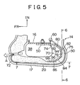
- An air bag module 38 and a support bracket 40 are disposed in a cavity 42 formed between the frame 16 and the cushion 18 and fixed by studs 34 to the intermediate portion 24 of the frame 16.
- the air bag module 38 has the air bag 46 and an inflator 44.
- the inflator 44 is in the shape of an elongated cylinder and has ports (not shown) through which the inflator gas is discharged to inflate the air bag 46.
- the inflator 44 contains chemicals for generating an inflator gas for discharge at the time of deployment of the air bag.
- the air bag 46 is made of any conventional fabric material which is suitable for air bag construction. The air bag 46 is folded in the cavity 42.
- a front end 59 of the strap 58 is sewn on the inner surface of the trim cover 20 near an edge 61 forming the seam line 32 of the trim cover 20.
- the strap 58 extends to a U-shaped clip 60 which is mounted to the rear end of the strap 58.
- the clip 60 engages the rear flange 22 of the frame 16.
- the strap 58 may be formed of any suitable flexible material having a low modulus of elasticity, such as the material from which seat belts are formed.
- the strap 58 is approximately 65mm in width, approximately 230mm in length and approximately 0.2 to 0.3mm in thickness. As shown in Figs.
- the reaction surface 76 is formed so that the thickness of the rear portion 30 of the cushion 18 sandwiched between the strap 72 and the reaction surface 76 is substantially constant from top to bottom of the strap 72.
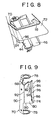
- the rear portion 30 of the cushion 18 shown in Fig. 5 is omitted. Therefore in Fig. 8, there is a gap formed between the corner panel portion 84 of the arm 74 and the strap 72.
- the strap 72 substantially uniformly supports the inner surface of the rear portion 30 of the cushion 18 on the arm 74 from top to bottom of the strap 72.
- FIG. 10 An air bag deployment apparatus according to a second embodiment of the present invention will be described hereinafter with reference to Figs. 10 through 14.
- This apparatus utilizes a support bracket 110 similar to that of the first embodiment with the strap 58 which extends through the aperture 62 in the cushion 18.
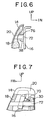
- the inflator 44 (the air bag module 38) is mounted to angle with respect to the rear surface of the seat in a direction generally parallel to the front surface of the seat, as is the case with the second embodiment shown in Fig. 7.
- the support bracket 110 may be stamped in one piece with a mounting portion 50 and an arm 112.
- the arm 112 has an inner panel portion 114, an intermediate panel portion 116 and an end panel portion 118.
- the inner panel portion 114 and the intermediate panel portion 116 extend generally laterally outwardly from the frame 16 towards the side surface 17 of the seat back 14.
- the support brackets 40, 70 and 110 of the first and second embodiments and of the comparative example also serve as a protector encompassing the air bag module 38. If an object has flung into the passenger seat in case of a side collision of the vehicle, the protector encompassing the air bag module protects the air bag module from the object.
- the first and second embodiments and the comparative example can provide the aforementioned effect without substantially increasing the number of parts in comparison with the conventional structure.
- the support brackets 40, 70 and 110 may be composed of separate parts, a support bracket 115 shown in Fig. 14 and an arm 140 having at its inner end a flange 142 to be mounted directly to the back of the frame 16.
Landscapes
- Engineering & Computer Science (AREA)
- Mechanical Engineering (AREA)
- Air Bags (AREA)
- Seats For Vehicles (AREA)
Priority Applications (1)
| Application Number | Priority Date | Filing Date | Title |
|---|---|---|---|
| EP06100534.4A EP1657126B1 (en) | 1999-03-10 | 2000-03-09 | Air bag deployment apparatus for vehicle seat |
Applications Claiming Priority (2)
| Application Number | Priority Date | Filing Date | Title |
|---|---|---|---|
| US09/266,098 US6213498B1 (en) | 1999-03-10 | 1999-03-10 | Seat back air bag deployment system |
| US266098 | 1999-03-10 |
Related Child Applications (1)
| Application Number | Title | Priority Date | Filing Date |
|---|---|---|---|
| EP06100534.4A Division EP1657126B1 (en) | 1999-03-10 | 2000-03-09 | Air bag deployment apparatus for vehicle seat |
Publications (3)
| Publication Number | Publication Date |
|---|---|
| EP1034989A2 EP1034989A2 (en) | 2000-09-13 |
| EP1034989A3 EP1034989A3 (en) | 2003-05-07 |
| EP1034989B1 true EP1034989B1 (en) | 2006-07-05 |
Family
ID=23013171
Family Applications (2)
| Application Number | Title | Priority Date | Filing Date |
|---|---|---|---|
| EP00105020A Expired - Lifetime EP1034989B1 (en) | 1999-03-10 | 2000-03-09 | Vehicle seat with an air bag deployment apparatus |
| EP06100534.4A Expired - Lifetime EP1657126B1 (en) | 1999-03-10 | 2000-03-09 | Air bag deployment apparatus for vehicle seat |
Family Applications After (1)
| Application Number | Title | Priority Date | Filing Date |
|---|---|---|---|
| EP06100534.4A Expired - Lifetime EP1657126B1 (en) | 1999-03-10 | 2000-03-09 | Air bag deployment apparatus for vehicle seat |
Country Status (4)
| Country | Link |
|---|---|
| US (1) | US6213498B1 (enExample) |
| EP (2) | EP1034989B1 (enExample) |
| JP (1) | JP4000740B2 (enExample) |
| DE (1) | DE60029153T2 (enExample) |
Families Citing this family (30)
| Publication number | Priority date | Publication date | Assignee | Title |
|---|---|---|---|---|
| US6450528B1 (en) * | 1998-10-01 | 2002-09-17 | Toyota Jidosha Kabushiki Kaisha | Vehicle seat housing an airbag device |
| US6357789B1 (en) * | 1999-06-24 | 2002-03-19 | Ts Tech Co., Ltd. | Seat provided with side air bag system |
| JP3472537B2 (ja) | 2000-09-06 | 2003-12-02 | 本田技研工業株式会社 | 側面衝突用エアバッグ装置 |
| DE10321459A1 (de) * | 2003-05-13 | 2004-12-02 | Trw Occupant Restraint Systems Gmbh & Co. Kg | Sitzintegriertes Fahrzeuginsassen-Rückhaltesystem |
| US7377542B2 (en) | 2004-12-01 | 2008-05-27 | Lear Corporation | Vehicle seat side air bag system |
| US20060113765A1 (en) * | 2004-12-01 | 2006-06-01 | Lear Corporation | Vehicle seat side air bag system |
| DE102005042026B4 (de) * | 2005-09-02 | 2012-10-04 | Autoliv Development Ab | Vorhanggassack-Einheit |
| DE102006007301B4 (de) * | 2006-02-16 | 2010-09-09 | Lear Corporation, Southfield | Fahrzeugsitz-Airbagführung mit einem flexiblen Paneel mit einer Befestigung über eine Dichtscheibe an einer inneren Extremität |
| DE102006023624B4 (de) * | 2006-05-19 | 2013-07-04 | Autoliv Development Ab | Baugruppe |
| JP4760533B2 (ja) * | 2006-05-26 | 2011-08-31 | 豊田合成株式会社 | エアバッグ装置 |
| US8210567B2 (en) * | 2006-07-18 | 2012-07-03 | Irvin Automotive Products, Inc. | Seat side airbag seam |
| DE102006053911B4 (de) * | 2006-11-15 | 2010-07-22 | Lear Corp., Southfield | Seitenairbaganordnung für einen Fahrzeugsitz |
| US7967328B2 (en) * | 2007-05-24 | 2011-06-28 | Irvin Automotive Products, Inc. | Continuous side airbag seam |
| US7677594B2 (en) * | 2007-06-29 | 2010-03-16 | Toyota Motor Engineering & Manufacturing North America, Inc. | Vehicle seat having a side airbag deployment strap |
| JP2009040229A (ja) * | 2007-08-09 | 2009-02-26 | Takata Corp | 側突用エアバッグ装置 |
| US7784819B2 (en) * | 2008-02-14 | 2010-08-31 | Gm Global Technology Operations, Inc. | Airbag system |
| US9120411B2 (en) * | 2008-07-14 | 2015-09-01 | Lear Corporation | Automotive seat foam pad assembly |
| US8113539B2 (en) * | 2008-07-29 | 2012-02-14 | Lear Corporation | Automotive seat trim cover |
| DE102008049505B4 (de) | 2008-09-29 | 2018-07-19 | GM Global Technology Operations LLC (n. d. Ges. d. Staates Delaware) | Airbaganordnung für einen Fahrzeugsitz sowie Fahrzeugsitz mit der Airbaganordnung |
| JP5309956B2 (ja) * | 2008-12-18 | 2013-10-09 | マツダ株式会社 | シート用サイドエアバッグ構造 |
| JP4877350B2 (ja) * | 2009-03-27 | 2012-02-15 | 豊田合成株式会社 | サイドエアバッグ装置 |
| DE102009016888A1 (de) * | 2009-04-08 | 2010-10-14 | GM Global Technology Operations, Inc., Detroit | Seitenschutzairbaganordnung |
| US20100295282A1 (en) * | 2009-05-21 | 2010-11-25 | Hyundai Motor Company | Seat with side airbag for vehicles |
| DE102009024142B4 (de) * | 2009-06-04 | 2016-05-12 | TAKATA Aktiengesellschaft | Airbagmodul für ein Kraftfahrzeug |
| DE102010045969A1 (de) * | 2010-09-18 | 2012-03-22 | Gm Global Technology Operations Llc (N.D.Ges.D. Staates Delaware) | Fahrzeugsitz mit einem Airbag |
| CN103228491B (zh) * | 2011-01-27 | 2015-03-25 | 丰田自动车株式会社 | 搭载了侧面安全气囊装置的汽车用座椅 |
| JP6105554B2 (ja) * | 2012-03-16 | 2017-03-29 | テイ・エス テック株式会社 | クッションパッド及び車両用シート |
| DE102013200077A1 (de) | 2013-01-04 | 2014-07-10 | Lear Corporation | Fahrzeugsitzanordnung mit einem Seiten-Airbag und einem Führungspaneel mit beabstandeten vorderen Enden zum Erzeugen einer Scherkraft |
| DE102013225053A1 (de) * | 2013-12-05 | 2015-06-11 | Autoliv Development Ab | Airbagmodul |
| GB2527824A (en) * | 2014-07-03 | 2016-01-06 | Nissan Motor Mfg Uk Ltd | Airbag assembly |
Family Cites Families (17)
| Publication number | Priority date | Publication date | Assignee | Title |
|---|---|---|---|---|
| JP3039089B2 (ja) * | 1991-11-22 | 2000-05-08 | タカタ株式会社 | 自動車の乗員頭部の保護装置 |
| JP3009021B2 (ja) | 1995-02-20 | 2000-02-14 | 池田物産株式会社 | 車両の側突用エアバッグ装置 |
| JP2848482B2 (ja) | 1995-03-24 | 1999-01-20 | 池田物産株式会社 | 車両の側突用エアバッグ装置 |
| US5639111A (en) | 1995-03-29 | 1997-06-17 | General Motors Corporation | Air bag module |
| CA2185296C (en) * | 1995-09-18 | 1999-07-13 | Yasunori Hasegawa | Seat structure having a side impact air bag apparatus |
| EP0768215B1 (en) * | 1995-10-11 | 2002-11-20 | Toyota Jidosha Kabushiki Kaisha | Seat structure having a side impact air bag apparatus |
| JP3305547B2 (ja) | 1995-10-30 | 2002-07-22 | 高島屋日発工業株式会社 | エアバッグ装置を備えた車輛用シート |
| JP3815833B2 (ja) | 1996-01-17 | 2006-08-30 | 豊田合成株式会社 | 側部用エアバッグ装置 |
| US5700028A (en) | 1996-03-19 | 1997-12-23 | General Motors Corporation | Air bag module with energy absorbing mounting bracket |
| JP3385852B2 (ja) * | 1996-05-31 | 2003-03-10 | 日産自動車株式会社 | 車両用エアバッグ装置 |
| JPH1053091A (ja) * | 1996-08-09 | 1998-02-24 | Nissan Motor Co Ltd | 車両用シートのエアバッグ装置 |
| DE19746387B4 (de) * | 1996-10-25 | 2004-06-24 | Honda Giken Kogyo K.K. | Airbagvorrichtung |
| JPH10157550A (ja) * | 1996-12-04 | 1998-06-16 | Ikeda Bussan Co Ltd | サイドエアバッグ装置 |
| US6045151A (en) * | 1997-02-28 | 2000-04-04 | Hoover Universal, Inc. | Seat mounted side air bag with deployment force concentrator |
| US5906390A (en) * | 1997-05-19 | 1999-05-25 | Trw Vehicle Safety Systems Inc. | Vehicle occupant protection apparatus |
| US5938232A (en) * | 1997-10-24 | 1999-08-17 | Breed Automotive Technology, Inc. | Force directing air bag deployment pocket |
| JPH11129855A (ja) * | 1997-10-31 | 1999-05-18 | Ts Tec Kk | サイドエアーバッグ装置を備える車輌用シート |
-
1999
- 1999-03-10 US US09/266,098 patent/US6213498B1/en not_active Expired - Lifetime
-
2000
- 2000-03-09 EP EP00105020A patent/EP1034989B1/en not_active Expired - Lifetime
- 2000-03-09 EP EP06100534.4A patent/EP1657126B1/en not_active Expired - Lifetime
- 2000-03-09 JP JP2000064770A patent/JP4000740B2/ja not_active Expired - Fee Related
- 2000-03-09 DE DE60029153T patent/DE60029153T2/de not_active Expired - Lifetime
Also Published As
| Publication number | Publication date |
|---|---|
| EP1034989A2 (en) | 2000-09-13 |
| EP1657126B1 (en) | 2015-07-29 |
| EP1034989A3 (en) | 2003-05-07 |
| EP1657126A2 (en) | 2006-05-17 |
| EP1657126A3 (en) | 2009-03-18 |
| US6213498B1 (en) | 2001-04-10 |
| DE60029153T2 (de) | 2007-06-06 |
| DE60029153D1 (de) | 2006-08-17 |
| JP4000740B2 (ja) | 2007-10-31 |
| JP2000280854A (ja) | 2000-10-10 |
Similar Documents
| Publication | Publication Date | Title |
|---|---|---|
| EP1034989B1 (en) | Vehicle seat with an air bag deployment apparatus | |
| US7695004B2 (en) | Airbag apparatus | |
| KR101219703B1 (ko) | 차량용 루프 에어백장치 | |
| US6561540B1 (en) | Seat structure having a side impact air bag apparatus | |
| US7699339B2 (en) | Bracket for securing side airbag for automotive vehicle | |
| US5997032A (en) | Seat with side air bag | |
| EP3900985B1 (en) | Side airbag device, vehicle seat provided with same, and method for manufacturing side airbag device | |
| EP1803614B1 (en) | Vehicle seat | |
| EP0856439A1 (en) | Side air bag-carrying seat structure | |
| JP5572348B2 (ja) | 車両用ルーフエアバッグ装置 | |
| JPH10203294A (ja) | シームレス側面膨張式拘束展開システム | |
| JP5330758B2 (ja) | シートバック構造 | |
| JP3528704B2 (ja) | エアバッグ装置を内蔵した車両用シート | |
| EP3521109A1 (en) | Side airbag apparatus | |
| JP2011068198A (ja) | エアバッグ装置を備えた車両用シート | |
| WO2019176966A1 (ja) | サイドエアバッグ装置 | |
| JP3642893B2 (ja) | サイドエアバッグ内蔵シートのシートパッド構造 | |
| KR100495037B1 (ko) | 차량의 사이드 에어백 장치 | |
| US7896388B2 (en) | Seat airbag | |
| US20220063547A1 (en) | Airbag apparatus for vehicle | |
| JP2011068197A (ja) | エアバッグ装置を備えた車両用シート | |
| JPH0986327A (ja) | 車体側部のエネルギ吸収構造 | |
| JP3402151B2 (ja) | エアバッグ装置 | |
| JP2010155575A (ja) | 乗員保護装置、及び車両 | |
| JP2019156173A (ja) | サイドエアバッグ装置 |
Legal Events
| Date | Code | Title | Description |
|---|---|---|---|
| PUAI | Public reference made under article 153(3) epc to a published international application that has entered the european phase |
Free format text: ORIGINAL CODE: 0009012 |
|
| 17P | Request for examination filed |
Effective date: 20000309 |
|
| AK | Designated contracting states |
Kind code of ref document: A2 Designated state(s): AT BE CH CY DE DK ES FI FR GB GR IE IT LI LU MC NL PT SE |
|
| AX | Request for extension of the european patent |
Free format text: AL;LT;LV;MK;RO;SI |
|
| PUAL | Search report despatched |
Free format text: ORIGINAL CODE: 0009013 |
|
| AK | Designated contracting states |
Designated state(s): AT BE CH CY DE DK ES FI FR GB GR IE IT LI LU MC NL PT SE |
|
| AX | Request for extension of the european patent |
Extension state: AL LT LV MK RO SI |
|
| 17Q | First examination report despatched |
Effective date: 20031112 |
|
| AKX | Designation fees paid |
Designated state(s): DE FR GB |
|
| GRAP | Despatch of communication of intention to grant a patent |
Free format text: ORIGINAL CODE: EPIDOSNIGR1 |
|
| RTI1 | Title (correction) |
Free format text: VEHICLE SEAT WITH AN AIR BAG DEPLOYMENT APPARATUS |
|
| RIN1 | Information on inventor provided before grant (corrected) |
Inventor name: SUZUKI, KOICHI Inventor name: GHALAMBOR, HALEH Inventor name: MIKUTSU, SATOSHI Inventor name: KATO, TAKEAKI |
|
| GRAS | Grant fee paid |
Free format text: ORIGINAL CODE: EPIDOSNIGR3 |
|
| GRAA | (expected) grant |
Free format text: ORIGINAL CODE: 0009210 |
|
| RIN1 | Information on inventor provided before grant (corrected) |
Inventor name: KATO, TAKEAKI Inventor name: SUZUKI, KOICHI Inventor name: GHALAMBOR, HALEH Inventor name: MIKUTSU, SATOSHI |
|
| AK | Designated contracting states |
Kind code of ref document: B1 Designated state(s): DE FR GB |
|
| REG | Reference to a national code |
Ref country code: GB Ref legal event code: FG4D |
|
| RIC1 | Information provided on ipc code assigned before grant |
Ipc: B60R 21/20 20060101AFI20060530BHEP |
|
| REF | Corresponds to: |
Ref document number: 60029153 Country of ref document: DE Date of ref document: 20060817 Kind code of ref document: P |
|
| ET | Fr: translation filed | ||
| PLBE | No opposition filed within time limit |
Free format text: ORIGINAL CODE: 0009261 |
|
| STAA | Information on the status of an ep patent application or granted ep patent |
Free format text: STATUS: NO OPPOSITION FILED WITHIN TIME LIMIT |
|
| 26N | No opposition filed |
Effective date: 20070410 |
|
| REG | Reference to a national code |
Ref country code: GB Ref legal event code: 746 Effective date: 20111114 |
|
| REG | Reference to a national code |
Ref country code: DE Ref legal event code: R084 Ref document number: 60029153 Country of ref document: DE Effective date: 20111109 |
|
| REG | Reference to a national code |
Ref country code: FR Ref legal event code: PLFP Year of fee payment: 17 |
|
| REG | Reference to a national code |
Ref country code: FR Ref legal event code: PLFP Year of fee payment: 18 |
|
| REG | Reference to a national code |
Ref country code: FR Ref legal event code: PLFP Year of fee payment: 19 |
|
| PGFP | Annual fee paid to national office [announced via postgrant information from national office to epo] |
Ref country code: DE Payment date: 20190226 Year of fee payment: 20 Ref country code: GB Payment date: 20190306 Year of fee payment: 20 |
|
| PGFP | Annual fee paid to national office [announced via postgrant information from national office to epo] |
Ref country code: DE Payment date: 20190226 Year of fee payment: 20 Ref country code: FR Payment date: 20190213 Year of fee payment: 20 |
|
| REG | Reference to a national code |
Ref country code: DE Ref legal event code: R071 Ref document number: 60029153 Country of ref document: DE |
|
| REG | Reference to a national code |
Ref country code: GB Ref legal event code: PE20 Expiry date: 20200308 |
|
| PG25 | Lapsed in a contracting state [announced via postgrant information from national office to epo] |
Ref country code: GB Free format text: LAPSE BECAUSE OF EXPIRATION OF PROTECTION Effective date: 20200308 |