EP1034989B1 - Vehicle seat with an air bag deployment apparatus - Google Patents
Vehicle seat with an air bag deployment apparatus Download PDFInfo
- Publication number
- EP1034989B1 EP1034989B1 EP00105020A EP00105020A EP1034989B1 EP 1034989 B1 EP1034989 B1 EP 1034989B1 EP 00105020 A EP00105020 A EP 00105020A EP 00105020 A EP00105020 A EP 00105020A EP 1034989 B1 EP1034989 B1 EP 1034989B1
- Authority
- EP
- European Patent Office
- Prior art keywords
- air bag
- strap
- cushion
- frame
- deployment
- Prior art date
- Legal status (The legal status is an assumption and is not a legal conclusion. Google has not performed a legal analysis and makes no representation as to the accuracy of the status listed.)
- Expired - Lifetime
Links
Images


Classifications
-
- B—PERFORMING OPERATIONS; TRANSPORTING
- B60—VEHICLES IN GENERAL
- B60R—VEHICLES, VEHICLE FITTINGS, OR VEHICLE PARTS, NOT OTHERWISE PROVIDED FOR
- B60R21/00—Arrangements or fittings on vehicles for protecting or preventing injuries to occupants or pedestrians in case of accidents or other traffic risks
- B60R21/02—Occupant safety arrangements or fittings, e.g. crash pads
- B60R21/16—Inflatable occupant restraints or confinements designed to inflate upon impact or impending impact, e.g. air bags
- B60R21/20—Arrangements for storing inflatable members in their non-use or deflated condition; Arrangement or mounting of air bag modules or components
- B60R21/207—Arrangements for storing inflatable members in their non-use or deflated condition; Arrangement or mounting of air bag modules or components in vehicle seats
-
- B—PERFORMING OPERATIONS; TRANSPORTING
- B60—VEHICLES IN GENERAL
- B60R—VEHICLES, VEHICLE FITTINGS, OR VEHICLE PARTS, NOT OTHERWISE PROVIDED FOR
- B60R21/00—Arrangements or fittings on vehicles for protecting or preventing injuries to occupants or pedestrians in case of accidents or other traffic risks
- B60R2021/0002—Type of accident
- B60R2021/0006—Lateral collision
-
- B—PERFORMING OPERATIONS; TRANSPORTING
- B60—VEHICLES IN GENERAL
- B60R—VEHICLES, VEHICLE FITTINGS, OR VEHICLE PARTS, NOT OTHERWISE PROVIDED FOR
- B60R21/00—Arrangements or fittings on vehicles for protecting or preventing injuries to occupants or pedestrians in case of accidents or other traffic risks
- B60R21/02—Occupant safety arrangements or fittings, e.g. crash pads
- B60R21/16—Inflatable occupant restraints or confinements designed to inflate upon impact or impending impact, e.g. air bags
- B60R2021/161—Inflatable occupant restraints or confinements designed to inflate upon impact or impending impact, e.g. air bags characterised by additional means for controlling deployment trajectory
-
- B—PERFORMING OPERATIONS; TRANSPORTING
- B60—VEHICLES IN GENERAL
- B60R—VEHICLES, VEHICLE FITTINGS, OR VEHICLE PARTS, NOT OTHERWISE PROVIDED FOR
- B60R21/00—Arrangements or fittings on vehicles for protecting or preventing injuries to occupants or pedestrians in case of accidents or other traffic risks
- B60R21/02—Occupant safety arrangements or fittings, e.g. crash pads
- B60R21/16—Inflatable occupant restraints or confinements designed to inflate upon impact or impending impact, e.g. air bags
- B60R21/20—Arrangements for storing inflatable members in their non-use or deflated condition; Arrangement or mounting of air bag modules or components
- B60R21/215—Arrangements for storing inflatable members in their non-use or deflated condition; Arrangement or mounting of air bag modules or components characterised by the covers for the inflatable member
- B60R21/2165—Arrangements for storing inflatable members in their non-use or deflated condition; Arrangement or mounting of air bag modules or components characterised by the covers for the inflatable member characterised by a tear line for defining a deployment opening
Definitions
- the strap may extend adjacent to the reaction surface.
- the support member may be a protector for protecting the air bag module from an impacting object outside a vehicle.
- An air bag module 38 and a support bracket 40 are disposed in a cavity 42 formed between the frame 16 and the cushion 18 and fixed by studs 34 to the intermediate portion 24 of the frame 16.
- the air bag module 38 has the air bag 46 and an inflator 44.
- the inflator 44 is in the shape of an elongated cylinder and has ports (not shown) through which the inflator gas is discharged to inflate the air bag 46.
- the inflator 44 contains chemicals for generating an inflator gas for discharge at the time of deployment of the air bag.
- the air bag 46 is made of any conventional fabric material which is suitable for air bag construction. The air bag 46 is folded in the cavity 42.
- a front end 59 of the strap 58 is sewn on the inner surface of the trim cover 20 near an edge 61 forming the seam line 32 of the trim cover 20.
- the strap 58 extends to a U-shaped clip 60 which is mounted to the rear end of the strap 58.
- the clip 60 engages the rear flange 22 of the frame 16.
- the strap 58 may be formed of any suitable flexible material having a low modulus of elasticity, such as the material from which seat belts are formed.
- the strap 58 is approximately 65mm in width, approximately 230mm in length and approximately 0.2 to 0.3mm in thickness. As shown in Figs.
- the reaction surface 76 is formed so that the thickness of the rear portion 30 of the cushion 18 sandwiched between the strap 72 and the reaction surface 76 is substantially constant from top to bottom of the strap 72.
- the rear portion 30 of the cushion 18 shown in Fig. 5 is omitted. Therefore in Fig. 8, there is a gap formed between the corner panel portion 84 of the arm 74 and the strap 72.
- the strap 72 substantially uniformly supports the inner surface of the rear portion 30 of the cushion 18 on the arm 74 from top to bottom of the strap 72.
- FIG. 10 An air bag deployment apparatus according to a second embodiment of the present invention will be described hereinafter with reference to Figs. 10 through 14.
- This apparatus utilizes a support bracket 110 similar to that of the first embodiment with the strap 58 which extends through the aperture 62 in the cushion 18.
- the inflator 44 (the air bag module 38) is mounted to angle with respect to the rear surface of the seat in a direction generally parallel to the front surface of the seat, as is the case with the second embodiment shown in Fig. 7.
- the support bracket 110 may be stamped in one piece with a mounting portion 50 and an arm 112.
- the arm 112 has an inner panel portion 114, an intermediate panel portion 116 and an end panel portion 118.
- the inner panel portion 114 and the intermediate panel portion 116 extend generally laterally outwardly from the frame 16 towards the side surface 17 of the seat back 14.
- the support brackets 40, 70 and 110 of the first and second embodiments and of the comparative example also serve as a protector encompassing the air bag module 38. If an object has flung into the passenger seat in case of a side collision of the vehicle, the protector encompassing the air bag module protects the air bag module from the object.
- the first and second embodiments and the comparative example can provide the aforementioned effect without substantially increasing the number of parts in comparison with the conventional structure.
- the support brackets 40, 70 and 110 may be composed of separate parts, a support bracket 115 shown in Fig. 14 and an arm 140 having at its inner end a flange 142 to be mounted directly to the back of the frame 16.
Landscapes
- Engineering & Computer Science (AREA)
- Mechanical Engineering (AREA)
- Air Bags (AREA)
- Seats For Vehicles (AREA)
Description
- The present invention relates to a vehicle seat comprising an air bag deployment apparatus for side impact and, more particularly, to an air bag deployment apparatus which is mounted in a seat back of a vehicle seat.
- In order to provide passengers of vehicles with protection from side impact, it is known to utilize air bags which are deployed from the vehicle seat back to extend between a passenger and a vehicle side wall or a door. In these air bag deployment apparatuses, an air bag module is mounted to the frame of the vehicle seat. A cushion extends over the air bag module and the frame. A trim cover in which a frangible seam line is formed extends over the cushion. Upon activation, the air bag ruptures the cushion and the frangible seam line in the trim cover to extend between the passenger and the vehicle side wall or the door from the seat back. Various methods have been used to ensure that the bag deploys properly. These include storing the bag within a box which has a frangible end to direct the direction of deployment, as disclosed in U.S. Patent No. 5, 700, 028.
- It is also known, as disclosed in Japanese Patent Application Laid-Open No. 8-258660, to direct the deployment of the air bag to a seam in the trim cover by means of a pair of flexible straps spaced apart from each other. One end of each strap is fixed to the frame and the other end is sewn to one side of a pair of trim covers sewn up along the seam line. The straps follow the inside contour of the cushions. When the inflator is activated, the air bag is inflated by the gas emitted from the inflator and deployed between two straps which direct the bag towards the seam in the trim cover.
- However, since the box harder than the cushions is disposed inside the seat back in the air bag deployment apparatus disclosed in the aforementioned U.S. Patent No. 5, 700, 028, the box hampers the cushioning performance of the seat back. This alters the ergonomics and comfort of the seat back.
- In the air bag deployment apparatus disclosed in Japanese Patent Application Laid-Open No. HEI 8-258660, the straps follow the contour of the foam so that the deployment of the air bag presses the cushions of the seat back outwardly. Thus, during deployment of the air bag, the air bag presses the cushion and then ruptures the seam line. This results in a loss of the energy for deployment of the air bag because part of it is used to press the cushion.
- On the other hand, Japanese Patent Application Laid-Open No. HEI 10-157550 which discloses the features of the preamble of claim 1 show an air bag system for a seat having a strap extending along the inside of a trim cover from a seam line and coupled to a rear portion of a frame. In this air bag system, the strap is disposed to encompass the side and rear portions of the air bag module. In order to ensure the cushioning performance of side and rear surfaces of the seat disclosed in this publication, it is considered to also provide the side and rear surfaces of the seat with cushions. In this case, it is considered that the strap extends between the cushion on the side portion of the seat and the trim cover from the seam line and then rearwardly of the cushion on the rear portion of the seat and is coupled to the frame. That is, the strap encompasses the cushions on the rear and side portions of the seat while it extends to the seam line from the frame. In such a construction, upon deployment of the air bag, the strap receives a deployment pressure of the air bag and is pulled forwardly. At this moment the strap compresses the cushion on the rear portion of the seat forwardly. The compression of the cushion brings about a loss in energy for deployment of the air bag. Also, since the strap is allowed to be displaced forwardly by a deformed amount of the cushion, the seam line may not be ruptured properly. If the cushion on the rear portion of the seat is thickened to enhance the cushioning performance of the rear surface of the seat or to arrange the air bag module in front of the seat back, the aforementioned problem becomes acute. Accordingly, it has been required to take a measure such as the boosting of the pressure of inflator gas for the purpose of rupturing the seam line with greater reliability.
- Document EP 0 788 940 A2 discloses a seat structure having a side impact air bag apparatus provided in a housing having a hinged lid. The housing is integrated into a side portion of a seat back which side portion opposes a vehicle door. The airbag is activated at the time of a side impact such that a sewn portion of a seat surface layer, which is formed by sewing a front seat surface layer for covering the front of the seat back to a side seat surface layer for covering the side of the seat back, breaks and an air bag body inflates between a side portion of a vehicle body and the side of a vehicle occupant.
- It is the object of the present invention to provide a vehicle seat comprising an air bag deployment apparatus for side impact which has a relatively low gas pressure for deployment and is easy to mount, inexpensive and ensures a certain and easy deployment.
- The present invention further provides an air bag deployment apparatus which demonstrates high stability in the direction of deployment and can maintain the ergonomics of a conventional seat.
- A first aspect of the present invention is given in claim 1.
- According to the first aspect of the present invention, since the strap is supported on the reaction surface of the support member, the amount of forward displacement of the strap is limited. Accordingly, the seam line to which the strap is coupled is inhibited from being displaced forwardly due to deformation of the cushion, which makes it possible to effectively transmit the deployment pressure of the air bag to the seam line and rupture the seam line with certainty. This results in stable deployment of the air bag and reduction in the loss of energy for deployment caused by excessive compression of the cushion. Thus, the gas pressure required for deployment of the air bag is significantly reduced.
- In the aforementioned aspect, the strap may extend adjacent to the reaction surface.
- In this construction, since the strap is adjacent to the reaction surface of the support member, the amount of forward displacement of the strap can be limited through contact between the strap and the reaction surface when the deployment pressure of the air bag acts on the strap. This makes it possible to effectively transmit the deployment pressure of the air bag to the seam line and rupture the seam line with certainty.
- In the aforementioned aspect, the strap may be disposed to penetrate an aperture in the cushion.
- In this construction, since the strap penetrates the aperture in the cushion, the strap can be extended between the side portions of the cushion and the trim cover at the shortest distance from the reaction surface of the support bracket (member), and the strap can be of relatively short length.
- In the aforementioned aspect, the cushion may have a rear portion extending rearwardly of the air bag module with a part of the rear portion being sandwiched between the reaction surface and the strap, and the sandwiched part of the rear portion may have a substantially uniform thickness from top to bottom of the strap.
- In this construction, the rear portion of the cushion sandwiched between the strap and the reaction surface has a substantially uniform thickness from top to bottom of the strap. Therefore the deployment pressure of the air bag is substantially uniformly transmitted to the rear portion of the cushion sandwiched between the strap and the reaction surface. This provides substantially uniform compression of the part of the cushion contacting the reaction surface during deployment of the air bag, whereby the deformed amount of that part becomes substantially uniform from top to bottom of the strap and the strap is inhibited from being twisted. Therefore, the magnitude and direction of the force transmitted to the seam line from the strap can be stabilized and the seam line can be ruptured with certainty. This provides stable deployment of the air bag in a predetermined direction. Moreover, since the thickness of the cushion can be adjusted by modifying the shape of the support member, even if the air bag module is disposed further forwardly of the seat, the air bag can be deployed properly. In addition, as application to vehicles of different types is made possible through a slight modification of the shape of the support member, the applicability of the air bag deployment apparatus improves.
- In the aforementioned aspect, a path of the strap extending in a fore-to-aft direction of the seat may form an acute angle with a direction of deployment of the air bag with respect to a height direction of the seat, and the arm may be formed of a plurality of panel portions extending substantially coplanar with the path of the strap.
- In this construction, even if the path of the strap extending in the fore-to-aft direction of the strap forms an acute angle with the direction of deployment of the air bag with respect to the height direction of the seat, the strap extends from the portion where it is coupled to the frame to the seam line without being twisted. This enables the deployment pressure of the air bag to be transmitted to the seam line with certainty.
- In the aforementioned aspect, the air bag module may be mounted to the frame through the support member.
- In this construction, the aforementioned effects can be achieved without substantially increasing the number of parts in comparison with the conventional structure.
- In the aforementioned aspect, the support member may have an end portion extending towards a front portion of the seat from the reaction surface.
- In the aforementioned aspect, at least a part of the strap may extend between the trim cover and the cushion.
- In the aforementioned aspect, the support member may be a protector for protecting the air bag module from an impacting object outside a vehicle.
- The foregoing and further objects, features and advantages of the present invention will become apparent from the following description of preferred embodiments with reference to the accompanying drawings, wherein:
- Fig. 1 is a perspective view schematically showing a vehicle seat fitted with an air bag deployment apparatus according to a first embodiment of the present invention;
- Fig. 2 is a partial sectional view of the vehicle seat fitted with the air bag deployment apparatus according to the first embodiment of the present invention, in a state prior to deployment of the air bag;
- Fig. 3 is a partial sectional view of the vehicle seat taken along a line 3-3 shown in Fig. 2;
- Fig. 4 is a partial sectional view of the vehicle seat fitted with the air bag deployment apparatus according to the first embodiment of the present invention, in a state of deployment of the air bag;
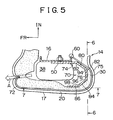
- Fig. 5 is a partial sectional view of a vehicle seat fitted with an air bag deployment apparatus according to a comparative example for better understanding the scope of the present invention, in a state prior to deployment of the air bag;
- Fig. 6 is a partial sectional view of the vehicle seat taken along a line 6-6 shown in Fig. 5;
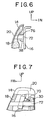
- Fig. 7 is a partial sectional view of the vehicle seat taken along a line 7-7 shown in Fig. 5;
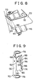
- Fig. 8 is a perspective view of the air bag deployment apparatus according to the comparative example for better understanding the scope of the present invention;
- Fig. 9 is a perspective view of a support bracket in the comparative example for better understanding the scope of the present invention;
- Fig. 10 is a partial sectional view of a vehicle seat fitted with an air bag deployment apparatus according to a second embodiment of the present invention;
- Fig. 11 is a perspective view of a support bracket in the second embodiment of the present invention;
- Fig. 12 is a top view of the support bracket in the second embodiment of the present invention;
- Fig. 13 is a top view of a modification example of the support bracket in the second embodiment of the present invention; and
- Fig. 14 is a top view of another modification example of the support bracket in the second embodiment of the present invention.
- Respective embodiments as well as one comparative example of the present invention will be described hereinafter with reference to the accompanying drawings. In the accompanying drawings, arrows FR, IN and UP denote directions to front, central and upper parts of a vehicle respectively.
- Figs. 1 through 4 show an air bag deployment apparatus according to a first embodiment of the present invention. Fig. 1 shows a
seat 12 composed of aseat cushion 13 and a seat back 14. The seat back 14 has twoside surfaces 17 and afront surface 15 extending between the side surfaces 17. Thefront surface 15 is formed to support a passenger. As shown in Fig. 2, the seat back 14 has acushion 18, atrim cover 20 covering an outer periphery of thecushion 18, and a generallyU-shaped frame 16 supporting thecushion 18 and thetrim cover 20. Theframe 16 can be formed of a rigid material such as metal or carbon fiber composite material. Theframe 16 has anintermediate portion 24 on a horizontal cross-section and arear flange 22 extending from theintermediate portion 24. Thecushion 18 has a generally C-shaped cross-section with two side portions 28 (only one of them is shown in Fig. 2), afront portion 26 coupling front ends of theside portions 28 to each other, andrear portions 30 extending from rear ends of therespective side portions 28 towards the center of the seat. Therear portions 30 of thecushion 18 serve to ensure cushioning properties when theseat 12 is touched from behind. Thecushion 18 can be formed of a known foam material. Thecushion 18 encompasses theframe 16 so that theframe 16 is sandwiched between thefront portion 26 and therear portions 30 of thecushion 18. - As shown in Fig. 2, the outer periphery of the
cushion 18 is covered with thetrim cover 20 which is formed from fabric or leather. Thetrim cover 20 has a vertically extendingfrangible seam line 32. Theseam line 32 extends vertically along thefront surface 15 of the seat back 14 in the neighborhood of a corner portion formed by thefront surface 15 and theside surface 17. Theseam line 32 has sufficient length to permit deployment of anair bag 46. However, theseam line 32 may be replaced with a seam line extending along the full height of the seat. - An
air bag module 38 and asupport bracket 40 are disposed in acavity 42 formed between theframe 16 and thecushion 18 and fixed by studs 34 to theintermediate portion 24 of theframe 16. Theair bag module 38 has theair bag 46 and aninflator 44. The inflator 44 is in the shape of an elongated cylinder and has ports (not shown) through which the inflator gas is discharged to inflate theair bag 46. The inflator 44 contains chemicals for generating an inflator gas for discharge at the time of deployment of the air bag. Theair bag 46 is made of any conventional fabric material which is suitable for air bag construction. Theair bag 46 is folded in thecavity 42. To elaborate in detail, theair bag 46 is coupled in thecavity 42 to the front surface of the inflator 44, that is, the surface closer to theseam line 32. In this embodiment, theair bag module 38, theinflator 44 and theair bag 46 may be of a conventional type. - As shown in Figs. 1 and 2, the
support bracket 40 has anarm 57 extending generally outwardly towards theside portions 28 of thecushion 18 from a mountingportion 50 for theframe 16. The mountingportion 50 of thesupport bracket 40 may be of any shape necessary to conform to the surface of theframe 16 and support thearm 57 extending outwardly and laterally from theframe 16 to the vicinity of theside surface 17 of the seat back 14. The mountingportion 50 has apertures (not shown) into which the studs 34 are inserted. Thearm 57 has aninner panel portion 54, anintermediate panel portion 55, and anend panel portion 56. Theinner panel portion 54 inclines rearwardly and outwardly from the mountingportion 50 and conforms with an angled portion of theframe 16. Theintermediate panel portion 55 extends laterally from a rear end of theinner panel portion 54 towards theside surface 17 of the seat back. Theend panel portion 56 is bent approximately 90° from theintermediate panel portion 55 to be parallel to theside surface 17 of the seat back, and extends forwardly. The rear surface of theintermediate panel portion 55 forms areaction surface 52 for supporting astrap 58. Thesupport bracket 40 can be formed in a known manner from a rigid material such as metal. - As shown in Figs. 1 and 2, a
front end 59 of thestrap 58 is sewn on the inner surface of thetrim cover 20 near anedge 61 forming theseam line 32 of thetrim cover 20. Thestrap 58 extends to aU-shaped clip 60 which is mounted to the rear end of thestrap 58. Theclip 60 engages therear flange 22 of theframe 16. Thestrap 58 may be formed of any suitable flexible material having a low modulus of elasticity, such as the material from which seat belts are formed. In this embodiment, thestrap 58 is approximately 65mm in width, approximately 230mm in length and approximately 0.2 to 0.3mm in thickness. As shown in Figs. 2 and 3, thestrap 58 extends from theframe 16 along thereaction surface 52 of theintermediate panel portion 55 of thesupport bracket 40 and through anaperture 62 in thecushion 18. Theaperture 62 extends laterally through theside portion 28 of thecushion 18. Theaperture 62 is approximately 20mm in width in the fore-to-aft direction and 100mm in height to freely accept thestrap 58 therethrough. After exiting theaperture 62 thestrap 58 turns approximately 90° to extend between thetrim cover 20 and theside portion 28 of thecushion 18 to theseam line 32. - It will be described hereinafter how the first embodiment of the present invention functions.
- As shown in Fig. 2, the
air bag 46 deploys generally in the direction of theseam line 32 as shown by the arrow "A". As is apparent from Fig. 4, thestrap 58 receives a deployment pressure from theair bag 46 and ruptures theseam line 32 during deployment of theair bag 46. More specifically, if the inflator gas emits from the inflator 44, theair bag 46 is urged to expand laterally and forwardly. At this moment, theside portions 28 and thecentral portion 26 of thecushion 18 are pressed due to the deployment pressure of theair bag 46. Because the outer periphery of thecushion 18 is encompassed by thestrap 58 which has a low modulus of elasticity and thus is unlikely to be elongated, the deployment pressure of theair bag 46 acting on theside portions 28 is transmitted to theseam line 32 by thestrap 58. Therefore theseam line 32 can be ruptured with certainty at the initial stage of deployment of theair bag 46. In response to the rupture of theseam line 32, thecushion 18 is ruptured upon receipt of the deployment pressure of theair bag 46. Theair bag 46 deploys outwardly through the ruptured location of thecushion 18. At this moment, in response to the deployment pressure of theair bag 46, a small amount of thecushion 18 adjacent to theend panel portion 56 is compressed against theend panel portion 56 of thesupport bracket 40. However, since the rear portion of thestrap 58 is supported by thereaction surface 52 of thesupport bracket 40, the amount of forward displacement of thestrap 58 is limited. Therefore, theseam line 32 to which thestrap 58 is coupled is inhibited from being displaced forwardly due to deformation of thecushion 18, and it is possible to effectively transmit the deployment pressure of theair bag 46 to theseam line 32 and rupture it with certainty. This results in stable deployment of theair bag 46 and a reduction in the loss of energy for deployment of theair bag 46 caused by excessive compression of thecushion 18. Thus the gas pressure required for the inflator 44 to deploy the air bag can significantly be reduced. In other words, it becomes possible to use the inflator 44 with a low output. - In this embodiment, since the
strap 58 penetrates theaperture 62, thestrap 58 can be extended between theside portions 28 of thecushion 18 and thetrim cover 20 at the shortest distance from thereaction surface 52 of thesupport bracket 40, and thestrap 58 can be of a relatively short length. If thestrap 58 is inserted into theaperture 62 through a slit (not shown) formed in theaperture 62 to communicate with the outer surface of thecushion 18, the mounting operation of thestrap 58 is facilitated and the operability in assembling the seat improves. - An air bag deployment apparatus according to comparative example for better understanding the scope of the present invention will be described hereinafter with reference to Figs. 5 through 9.
- The comparative example for better understanding the scope is different from the first embodiment in that it includes a modified
support bracket 70 and astrap 72 which loops around thecushion 18. In addition, the comparative example for better understanding the scope dispenses with theaperture 62 of thecushion 18 as mentioned in the description of the first embodiment. As shown in Fig. 5, thesupport bracket 70 has anarm 74 with areaction surface 76 which is formed to be parallel to the path of thestrap 72 as it travels in a path around thecushion 18. Thestrap 72 extends from theframe 16 rearwardly to the inside of thetrim cover 20 at arear surface 75 of the seat back 74 and then passes through the outside of thecushion 18 and the inside of thetrim cover 20. Thestrap 72 then extends along the inside of thetrim cover 20 to theseam line 32. - As shown in Figs. 7 and 9, the
support bracket 70 includes the mountingportion 50 with a pair of upper andlower rings 78 for holding the inflator (not shown) and thearm 74. As for the contour of the seat back 14, since the front surface may be angled with respect to the back surface as shown in Fig. 7 and the side surface may be sloped laterally and upwardly towards the center as shown in Fig. 6, thearm 74 has four panel portions which are formed to be generally parallel to the path of thestrap 72. Figs. 6 and 7 are sectional views which are taken along lines 6-6 and 7-7 shown in Fig. 5 respectively. To furnish a clear illustration, these sectional views additionally show thestrap 72. The inflator (the air bag module) is secured to be generally parallel to the front surface of the seat. That is, thearm 74 has aninner panel portion 80, arear panel portion 82, acorner panel portion 84 and anend panel portion 86 as shown in Fig. 9. - The
inner panel portion 80 extends from atop edge 88 to abottom edge 90 of thearm 74 and between afirst bend line 92 and asecond bend line 94. Theinner panel portion 80 extends at an angle towards therear surface 75 of the seat back 14 from thefirst bend line 92 of the mountingportion 50 as shown in Fig. 5. Therear panel portion 82 is wedge-shaped and defined by thesecond bend line 94 and athird bend line 96. Therear panel portion 82 extends generally parallel to therear surface 75 of the seat back. Thecorner panel portion 84 is wedge-shaped and defined by thethird bend line 96 and afourth bend line 98. - As shown in Figs. 7 and 9, the
corner panel portion 84 is wider at thetop edge 88 than at thelower edge 90 and angles to be generally parallel to the contour of the seat back 14 as it turns from the rear portion along the inner surface of thetrim cover 20, so that theupper edge 88 is located closer to the inflator 44 than thebottom edge 90. Theend panel portion 86 has a wedge-shape which is wider at thebottom edge 90 than at thetop edge 88 and angles to be generally parallel to theside surface 17 of the seat back 14 so that thetop edge 88 is located closer to the inflator 44 than thebottom edge 90. Thus, thearm 74 is smaller at thetop edge 88 than at thebottom edge 90. - As shown in Fig. 5, the
reaction surface 76 is formed so that the thickness of therear portion 30 of thecushion 18 sandwiched between thestrap 72 and thereaction surface 76 is substantially constant from top to bottom of thestrap 72. In Fig. 8, therear portion 30 of thecushion 18 shown in Fig. 5 is omitted. Therefore in Fig. 8, there is a gap formed between thecorner panel portion 84 of thearm 74 and thestrap 72. Thestrap 72 substantially uniformly supports the inner surface of therear portion 30 of thecushion 18 on thearm 74 from top to bottom of thestrap 72. The uniform contact relationship between thearm 74 and the inner surface of therear portion 30 of thecushion 18 serves to substantially uniformly transmit the deployment pressure of theair bag 46 to therear portion 30 of thecushion 18 sandwiched between thestrap 72 and thereaction surface 76. This ensures that the part of therear portion 30 of thecushion 18 contacting thearm 74 is substantially uniformly pressed during deployment of the air bag. Thus, the rear portion of the cushion is deformed substantially uniformly from top to bottom of thestrap 72, which inhibits thestrap 72 from being twisted. Therefore, the magnitude and direction of the force transmitted to theseam line 32 from thestrap 72 can be stabilized and theseam line 32 can be ruptured with certainty. This provides stable deployment of theair bag 46 in a predetermined direction. - In this comparative example, since the shape of the
support bracket 70 is modified to adjust the thickness of thecushion 18, theair bag 46 can be deployed appropriately even if theair bag module 38 is disposed further forwardly of the seat back 14. Because application to vehicles of different types is made possible through a slight modification of the shape of thesupport bracket 70, the applicability of the air bag deployment apparatus improves. - An air bag deployment apparatus according to a second embodiment of the present invention will be described hereinafter with reference to Figs. 10 through 14. This apparatus utilizes a
support bracket 110 similar to that of the first embodiment with thestrap 58 which extends through theaperture 62 in thecushion 18. In the second embodiment, the inflator 44 (the air bag module 38) is mounted to angle with respect to the rear surface of the seat in a direction generally parallel to the front surface of the seat, as is the case with the second embodiment shown in Fig. 7. As shown in Figs. 11 and 12, thesupport bracket 110 may be stamped in one piece with a mountingportion 50 and anarm 112. Thearm 112 has aninner panel portion 114, anintermediate panel portion 116 and anend panel portion 118. Theinner panel portion 114 and theintermediate panel portion 116 extend generally laterally outwardly from theframe 16 towards theside surface 17 of the seat back 14. - As shown in Figs. 11 and 12, the
intermediate panel portion 116 and theend panel portion 118 angle so that atop edge 122 of thearm 112 is located closer to the inflator 44 than abottom edge 120 of thearm 112. Thus, thearm 112 is wider at thebottom edge 120 than at thetop edge 122. In other words, thestrap 58 extends along thearm 112 from the portion where theclip 60 is attached to theframe 16, in a direction inclined with respect to the plumb line. By using thesupport bracket 110 thus formed, thestrap 58 extends perpendicularly to the axis of the inflator (the air bag module), that is, parallel to the direction of deployment of the air bag near the portion where thestrap 58 is coupled to theframe 16, and extends generally horizontally on the side surfaces of the seat. Thus, as is the case with the comparative example shown in Fig. 7, the direction perpendicular to the axis of the inflator, that is, the direction of deployment of the air bag forms an acute angle with the path of thestrap 58 in the fore-to-aft direction of the seat with respect to the height direction of the seat when viewed from the side surface. By using thesupport bracket 110, thestrap 58 extends from the portion where it is coupled to theframe 16 to theseam line 32 without being twisted. This enables the deployment pressure of the air bag to be transmitted to the seam line with certainty. At the moment of deployment of the air bag, thestrap 58 substantially uniformly contacts thearm 112 without unilaterally touching the top or bottom edge of thearm 112, whereby the deployment pressure of the air bag can be transmitted to the seam line with certainty. - The
support brackets air bag module 38. If an object has flung into the passenger seat in case of a side collision of the vehicle, the protector encompassing the air bag module protects the air bag module from the object. Thus, the first and second embodiments and the comparative example can provide the aforementioned effect without substantially increasing the number of parts in comparison with the conventional structure. - The
support brackets portion 132 and anarm 134 which are welded together as is apparent from asupport bracket 134 shown in Fig. 13. - The
support brackets support bracket 115 shown in Fig. 14 and anarm 140 having at its inner end aflange 142 to be mounted directly to the back of theframe 16. - While the present invention has been described with reference to what are presently considered to be preferred embodiments thereof, it is to be understood that the present invention is not limited to the disclosed embodiments or constructions. On the contrary, the present invention is intended to cover various modifications and equivalent arrangements. In addition, while the various elements of the disclosed invention are shown in various combinations and configurations which are exemplary, other combinations and configurations, including more, less or only a single embodiment, may also be within the scope of the present invention, solely as defined by the appending claims.
Claims (8)
- A vehicle seat comprising:a seat back (14) having a frame (16), a cushion (18) extending about the frame (16) to form a cavity (42) and a trim cover (20) extending over the cushion (18) and having a frangible seam line (32)an air bag deployment apparatus with an air bag module (38) mounted to the frame (16) within the cavity (42) and a strap (58; 72), one end of the strap (58; 72) being attached to the frame (16) and the other end being attached to the trim cover (20) at the seam line (32);characterized in that
the vehicle seat further comprises a support member (40, 70, 110) mounted to the frame (16) and having an arm (57; 74; 112; 134; 140) extending from the frame (16) towards a side portion of the seat back (14) to form a reaction surface (52; 76) on one side, and encompassing the air bag module (38), and in that said strap (58; 72) is extending behind the reaction surface (52; 76) from the frame (16) to the side portion of the seat back (14) and extending adjacent to the reaction surface (52) and
in that a part of the cushion (18) is located at least at a side of the airbag module (38) in a vehicular lateral direction. - The vehicle seat according to claim 1, characterized in that the strap (58) is disposed to penetrate an aperture (62) in the cushion (18).
- The vehicle seat according to claim 2, characterized in that said strap (58) extends between the trim cover (20) and said part of the cushion (18) located at the side of the air bag module (38) in the vehicular lateral direction.
- The vehicle seat according to claim 1, characterized in that a path of the strap (72) extending in a fore-to-aft direction of the seat forms an acute angle with a direction of deployment of the air bag with respect to a height direction of the seat, and that the arm (112) is formed of a plurality of panel portions (114, 116, 118) extending substantially coplanar with the path of the strap (72).
- The vehicle seat according to one of claims 1 to 4, characterized in that the air bag module (38) is mounted to the frame (16) through the support member (40; 70; 110).
- The vehicle seat according to one of claims 1 to 5, characterized in that the support member (40; 70; 110) has an end portion (56, 86, 118) extending towards a front portion of the seat from the reaction surface (52; 76).
- The vehicle seat according to one of claims 1, 2 and 4 to 6, characterized in that at least a part of the strap (58, 72) extends between the trim cover (20) and the cushion (18).
- The vehicle seat according to one of claims 1 to 7, characterized in that the support member (40; 70; 110) is a protector for protecting the air bag module (38) from an object impacting from the outside of a vehicle.
Priority Applications (1)
| Application Number | Priority Date | Filing Date | Title |
|---|---|---|---|
| EP06100534.4A EP1657126B1 (en) | 1999-03-10 | 2000-03-09 | Air bag deployment apparatus for vehicle seat |
Applications Claiming Priority (2)
| Application Number | Priority Date | Filing Date | Title |
|---|---|---|---|
| US09/266,098 US6213498B1 (en) | 1999-03-10 | 1999-03-10 | Seat back air bag deployment system |
| US266098 | 1999-03-10 |
Related Child Applications (1)
| Application Number | Title | Priority Date | Filing Date |
|---|---|---|---|
| EP06100534.4A Division EP1657126B1 (en) | 1999-03-10 | 2000-03-09 | Air bag deployment apparatus for vehicle seat |
Publications (3)
| Publication Number | Publication Date |
|---|---|
| EP1034989A2 EP1034989A2 (en) | 2000-09-13 |
| EP1034989A3 EP1034989A3 (en) | 2003-05-07 |
| EP1034989B1 true EP1034989B1 (en) | 2006-07-05 |
Family
ID=23013171
Family Applications (2)
| Application Number | Title | Priority Date | Filing Date |
|---|---|---|---|
| EP06100534.4A Expired - Lifetime EP1657126B1 (en) | 1999-03-10 | 2000-03-09 | Air bag deployment apparatus for vehicle seat |
| EP00105020A Expired - Lifetime EP1034989B1 (en) | 1999-03-10 | 2000-03-09 | Vehicle seat with an air bag deployment apparatus |
Family Applications Before (1)
| Application Number | Title | Priority Date | Filing Date |
|---|---|---|---|
| EP06100534.4A Expired - Lifetime EP1657126B1 (en) | 1999-03-10 | 2000-03-09 | Air bag deployment apparatus for vehicle seat |
Country Status (4)
| Country | Link |
|---|---|
| US (1) | US6213498B1 (en) |
| EP (2) | EP1657126B1 (en) |
| JP (1) | JP4000740B2 (en) |
| DE (1) | DE60029153T2 (en) |
Families Citing this family (29)
| Publication number | Priority date | Publication date | Assignee | Title |
|---|---|---|---|---|
| US6450528B1 (en) * | 1998-10-01 | 2002-09-17 | Toyota Jidosha Kabushiki Kaisha | Vehicle seat housing an airbag device |
| US6357789B1 (en) * | 1999-06-24 | 2002-03-19 | Ts Tech Co., Ltd. | Seat provided with side air bag system |
| DE10321459A1 (en) * | 2003-05-13 | 2004-12-02 | Trw Occupant Restraint Systems Gmbh & Co. Kg | Seat-integrated vehicle occupant restraint system |
| US20060113765A1 (en) * | 2004-12-01 | 2006-06-01 | Lear Corporation | Vehicle seat side air bag system |
| US7377542B2 (en) | 2004-12-01 | 2008-05-27 | Lear Corporation | Vehicle seat side air bag system |
| DE102005042026B4 (en) * | 2005-09-02 | 2012-10-04 | Autoliv Development Ab | Curtain airbag unit |
| DE102006007301B4 (en) * | 2006-02-16 | 2010-09-09 | Lear Corporation, Southfield | Vehicle seat airbag guide having a flexible panel with attachment via a sealing washer on an inner extremity |
| DE102006023624B4 (en) * | 2006-05-19 | 2013-07-04 | Autoliv Development Ab | module |
| JP4760533B2 (en) * | 2006-05-26 | 2011-08-31 | 豊田合成株式会社 | Airbag device |
| US8210567B2 (en) * | 2006-07-18 | 2012-07-03 | Irvin Automotive Products, Inc. | Seat side airbag seam |
| DE102006053911B4 (en) * | 2006-11-15 | 2010-07-22 | Lear Corp., Southfield | Side airbag assembly for a vehicle seat |
| US7967328B2 (en) * | 2007-05-24 | 2011-06-28 | Irvin Automotive Products, Inc. | Continuous side airbag seam |
| US7677594B2 (en) * | 2007-06-29 | 2010-03-16 | Toyota Motor Engineering & Manufacturing North America, Inc. | Vehicle seat having a side airbag deployment strap |
| JP2009040229A (en) * | 2007-08-09 | 2009-02-26 | Takata Corp | Airbag device for side impact |
| US7784819B2 (en) * | 2008-02-14 | 2010-08-31 | Gm Global Technology Operations, Inc. | Airbag system |
| US9120411B2 (en) * | 2008-07-14 | 2015-09-01 | Lear Corporation | Automotive seat foam pad assembly |
| US8113539B2 (en) * | 2008-07-29 | 2012-02-14 | Lear Corporation | Automotive seat trim cover |
| DE102008049505B4 (en) | 2008-09-29 | 2018-07-19 | GM Global Technology Operations LLC (n. d. Ges. d. Staates Delaware) | Airbag arrangement for a vehicle seat and vehicle seat with the airbag assembly |
| JP5309956B2 (en) * | 2008-12-18 | 2013-10-09 | マツダ株式会社 | Side airbag structure for seat |
| JP4877350B2 (en) * | 2009-03-27 | 2012-02-15 | 豊田合成株式会社 | Side airbag device |
| DE102009016888A1 (en) * | 2009-04-08 | 2010-10-14 | GM Global Technology Operations, Inc., Detroit | Side protection airbag arrangement for vehicle, has vehicle seat, which has seat frame, and airbag module with airbag |
| US20100295282A1 (en) * | 2009-05-21 | 2010-11-25 | Hyundai Motor Company | Seat with side airbag for vehicles |
| DE102009024142B4 (en) * | 2009-06-04 | 2016-05-12 | TAKATA Aktiengesellschaft | Airbag module for a motor vehicle |
| DE102010045969A1 (en) * | 2010-09-18 | 2012-03-22 | Gm Global Technology Operations Llc (N.D.Ges.D. Staates Delaware) | Vehicle seat with an airbag |
| WO2012101809A1 (en) * | 2011-01-27 | 2012-08-02 | トヨタ自動車株式会社 | Automobile seat containing side-airbag device |
| WO2013137355A1 (en) * | 2012-03-16 | 2013-09-19 | テイ・エス テック株式会社 | Cushion pad and vehicle seat |
| DE102013200077A1 (en) | 2013-01-04 | 2014-07-10 | Lear Corporation | A vehicle seat assembly having a side airbag and a guide panel with spaced forward ends for generating a shear force |
| DE102013225053A1 (en) * | 2013-12-05 | 2015-06-11 | Autoliv Development Ab | airbag module |
| GB2527824A (en) * | 2014-07-03 | 2016-01-06 | Nissan Motor Mfg Uk Ltd | Airbag assembly |
Family Cites Families (17)
| Publication number | Priority date | Publication date | Assignee | Title |
|---|---|---|---|---|
| JP3039089B2 (en) * | 1991-11-22 | 2000-05-08 | タカタ株式会社 | Car occupant head protection device |
| JP3009021B2 (en) | 1995-02-20 | 2000-02-14 | 池田物産株式会社 | Airbag device for vehicle side collision |
| JP2848482B2 (en) | 1995-03-24 | 1999-01-20 | 池田物産株式会社 | Airbag device for side collision of vehicles |
| US5639111A (en) | 1995-03-29 | 1997-06-17 | General Motors Corporation | Air bag module |
| CA2185296C (en) * | 1995-09-18 | 1999-07-13 | Yasunori Hasegawa | Seat structure having a side impact air bag apparatus |
| DE69624892T2 (en) * | 1995-10-11 | 2003-08-28 | Toyota Jidosha K.K., Toyota | Seat structure with a side impact airbag arrangement |
| JP3305547B2 (en) | 1995-10-30 | 2002-07-22 | 高島屋日発工業株式会社 | Vehicle seat with airbag device |
| JP3815833B2 (en) | 1996-01-17 | 2006-08-30 | 豊田合成株式会社 | Side airbag device |
| US5700028A (en) | 1996-03-19 | 1997-12-23 | General Motors Corporation | Air bag module with energy absorbing mounting bracket |
| JP3385852B2 (en) * | 1996-05-31 | 2003-03-10 | 日産自動車株式会社 | Vehicle airbag device |
| JPH1053091A (en) * | 1996-08-09 | 1998-02-24 | Nissan Motor Co Ltd | Air bag device of vehicular seat |
| DE19746387B4 (en) * | 1996-10-25 | 2004-06-24 | Honda Giken Kogyo K.K. | airbag device |
| JPH10157550A (en) * | 1996-12-04 | 1998-06-16 | Ikeda Bussan Co Ltd | Side air bag device |
| US6045151A (en) * | 1997-02-28 | 2000-04-04 | Hoover Universal, Inc. | Seat mounted side air bag with deployment force concentrator |
| US5906390A (en) * | 1997-05-19 | 1999-05-25 | Trw Vehicle Safety Systems Inc. | Vehicle occupant protection apparatus |
| US5938232A (en) * | 1997-10-24 | 1999-08-17 | Breed Automotive Technology, Inc. | Force directing air bag deployment pocket |
| JPH11129855A (en) * | 1997-10-31 | 1999-05-18 | Ts Tec Kk | Seat for vehicle provided with side air bag device |
-
1999
- 1999-03-10 US US09/266,098 patent/US6213498B1/en not_active Expired - Lifetime
-
2000
- 2000-03-09 JP JP2000064770A patent/JP4000740B2/en not_active Expired - Fee Related
- 2000-03-09 EP EP06100534.4A patent/EP1657126B1/en not_active Expired - Lifetime
- 2000-03-09 DE DE60029153T patent/DE60029153T2/en not_active Expired - Lifetime
- 2000-03-09 EP EP00105020A patent/EP1034989B1/en not_active Expired - Lifetime
Also Published As
| Publication number | Publication date |
|---|---|
| EP1034989A3 (en) | 2003-05-07 |
| EP1034989A2 (en) | 2000-09-13 |
| EP1657126A2 (en) | 2006-05-17 |
| DE60029153T2 (en) | 2007-06-06 |
| JP2000280854A (en) | 2000-10-10 |
| JP4000740B2 (en) | 2007-10-31 |
| DE60029153D1 (en) | 2006-08-17 |
| EP1657126B1 (en) | 2015-07-29 |
| US6213498B1 (en) | 2001-04-10 |
| EP1657126A3 (en) | 2009-03-18 |
Similar Documents
| Publication | Publication Date | Title |
|---|---|---|
| EP1034989B1 (en) | Vehicle seat with an air bag deployment apparatus | |
| US7695004B2 (en) | Airbag apparatus | |
| KR101219703B1 (en) | Roof airbag apparatus for vehicle | |
| US6561540B1 (en) | Seat structure having a side impact air bag apparatus | |
| US7699339B2 (en) | Bracket for securing side airbag for automotive vehicle | |
| EP1803614B1 (en) | Vehicle seat | |
| US5997032A (en) | Seat with side air bag | |
| EP0856439A1 (en) | Side air bag-carrying seat structure | |
| JP5572348B2 (en) | Roof airbag device for vehicle | |
| EP3900985A1 (en) | Side airbag device, vehicle seat provided with same, and method for manufacturing side airbag device | |
| JPH10203294A (en) | Seamless side expansion type constraint development system | |
| US7896388B2 (en) | Seat airbag | |
| JP3528704B2 (en) | Vehicle seat with built-in airbag device | |
| EP3521109A1 (en) | Side airbag apparatus | |
| US20200346611A1 (en) | A passenger protection apparatus | |
| JP5330758B2 (en) | Seat back structure | |
| JP2011068198A (en) | Seat for vehicle equipped with airbag device | |
| WO2019176966A1 (en) | Side airbag device | |
| KR20220142931A (en) | Side airbag assemblies and methods of assembly | |
| KR100495037B1 (en) | Side airbag device of the vehicle | |
| JP3642893B2 (en) | Seat pad structure for seat with built-in side airbag | |
| JP2011068197A (en) | Seat for vehicle equipped with airbag device | |
| JPH0986327A (en) | Energy absorbing structure at side part of body | |
| US11584330B2 (en) | Airbag apparatus for vehicle | |
| JP3402151B2 (en) | Airbag device |
Legal Events
| Date | Code | Title | Description |
|---|---|---|---|
| PUAI | Public reference made under article 153(3) epc to a published international application that has entered the european phase |
Free format text: ORIGINAL CODE: 0009012 |
|
| 17P | Request for examination filed |
Effective date: 20000309 |
|
| AK | Designated contracting states |
Kind code of ref document: A2 Designated state(s): AT BE CH CY DE DK ES FI FR GB GR IE IT LI LU MC NL PT SE |
|
| AX | Request for extension of the european patent |
Free format text: AL;LT;LV;MK;RO;SI |
|
| PUAL | Search report despatched |
Free format text: ORIGINAL CODE: 0009013 |
|
| AK | Designated contracting states |
Designated state(s): AT BE CH CY DE DK ES FI FR GB GR IE IT LI LU MC NL PT SE |
|
| AX | Request for extension of the european patent |
Extension state: AL LT LV MK RO SI |
|
| 17Q | First examination report despatched |
Effective date: 20031112 |
|
| AKX | Designation fees paid |
Designated state(s): DE FR GB |
|
| GRAP | Despatch of communication of intention to grant a patent |
Free format text: ORIGINAL CODE: EPIDOSNIGR1 |
|
| RTI1 | Title (correction) |
Free format text: VEHICLE SEAT WITH AN AIR BAG DEPLOYMENT APPARATUS |
|
| RIN1 | Information on inventor provided before grant (corrected) |
Inventor name: SUZUKI, KOICHI Inventor name: GHALAMBOR, HALEH Inventor name: MIKUTSU, SATOSHI Inventor name: KATO, TAKEAKI |
|
| GRAS | Grant fee paid |
Free format text: ORIGINAL CODE: EPIDOSNIGR3 |
|
| GRAA | (expected) grant |
Free format text: ORIGINAL CODE: 0009210 |
|
| RIN1 | Information on inventor provided before grant (corrected) |
Inventor name: KATO, TAKEAKI Inventor name: SUZUKI, KOICHI Inventor name: GHALAMBOR, HALEH Inventor name: MIKUTSU, SATOSHI |
|
| AK | Designated contracting states |
Kind code of ref document: B1 Designated state(s): DE FR GB |
|
| REG | Reference to a national code |
Ref country code: GB Ref legal event code: FG4D |
|
| RIC1 | Information provided on ipc code assigned before grant |
Ipc: B60R 21/20 20060101AFI20060530BHEP |
|
| REF | Corresponds to: |
Ref document number: 60029153 Country of ref document: DE Date of ref document: 20060817 Kind code of ref document: P |
|
| ET | Fr: translation filed | ||
| PLBE | No opposition filed within time limit |
Free format text: ORIGINAL CODE: 0009261 |
|
| STAA | Information on the status of an ep patent application or granted ep patent |
Free format text: STATUS: NO OPPOSITION FILED WITHIN TIME LIMIT |
|
| 26N | No opposition filed |
Effective date: 20070410 |
|
| REG | Reference to a national code |
Ref country code: GB Ref legal event code: 746 Effective date: 20111114 |
|
| REG | Reference to a national code |
Ref country code: DE Ref legal event code: R084 Ref document number: 60029153 Country of ref document: DE Effective date: 20111109 |
|
| REG | Reference to a national code |
Ref country code: FR Ref legal event code: PLFP Year of fee payment: 17 |
|
| REG | Reference to a national code |
Ref country code: FR Ref legal event code: PLFP Year of fee payment: 18 |
|
| REG | Reference to a national code |
Ref country code: FR Ref legal event code: PLFP Year of fee payment: 19 |
|
| PGFP | Annual fee paid to national office [announced via postgrant information from national office to epo] |
Ref country code: DE Payment date: 20190226 Year of fee payment: 20 Ref country code: GB Payment date: 20190306 Year of fee payment: 20 |
|
| PGFP | Annual fee paid to national office [announced via postgrant information from national office to epo] |
Ref country code: DE Payment date: 20190226 Year of fee payment: 20 Ref country code: FR Payment date: 20190213 Year of fee payment: 20 |
|
| REG | Reference to a national code |
Ref country code: DE Ref legal event code: R071 Ref document number: 60029153 Country of ref document: DE |
|
| REG | Reference to a national code |
Ref country code: GB Ref legal event code: PE20 Expiry date: 20200308 |
|
| PG25 | Lapsed in a contracting state [announced via postgrant information from national office to epo] |
Ref country code: GB Free format text: LAPSE BECAUSE OF EXPIRATION OF PROTECTION Effective date: 20200308 |