JP4760533B2 - Airbag device - Google Patents
Airbag device Download PDFInfo
- Publication number
- JP4760533B2 JP4760533B2 JP2006146894A JP2006146894A JP4760533B2 JP 4760533 B2 JP4760533 B2 JP 4760533B2 JP 2006146894 A JP2006146894 A JP 2006146894A JP 2006146894 A JP2006146894 A JP 2006146894A JP 4760533 B2 JP4760533 B2 JP 4760533B2
- Authority
- JP
- Japan
- Prior art keywords
- vehicle
- airbag
- inflating
- seat back
- deploying
- Prior art date
- Legal status (The legal status is an assumption and is not a legal conclusion. Google has not performed a legal analysis and makes no representation as to the accuracy of the status listed.)
- Active
Links
Images


Classifications
-
- B—PERFORMING OPERATIONS; TRANSPORTING
- B60—VEHICLES IN GENERAL
- B60R—VEHICLES, VEHICLE FITTINGS, OR VEHICLE PARTS, NOT OTHERWISE PROVIDED FOR
- B60R21/00—Arrangements or fittings on vehicles for protecting or preventing injuries to occupants or pedestrians in case of accidents or other traffic risks
- B60R21/02—Occupant safety arrangements or fittings, e.g. crash pads
- B60R21/16—Inflatable occupant restraints or confinements designed to inflate upon impact or impending impact, e.g. air bags
- B60R21/20—Arrangements for storing inflatable members in their non-use or deflated condition; Arrangement or mounting of air bag modules or components
- B60R21/207—Arrangements for storing inflatable members in their non-use or deflated condition; Arrangement or mounting of air bag modules or components in vehicle seats
Landscapes
- Engineering & Computer Science (AREA)
- Mechanical Engineering (AREA)
- Air Bags (AREA)
- Seats For Vehicles (AREA)
Description
本発明は、車両側方からの衝撃を緩和するために設けられるエアバッグ装置に関するものである。 The present invention relates to an airbag device provided to alleviate an impact from a side of a vehicle.
側突等、車両に側方からの衝撃が加わった場合にその衝撃から乗員等を保護する装置としてエアバッグ装置が知られている(特許文献1〜3参照)。同装置のエアバッグモジュールは、例えば、車両用シートのシートバック(背もたれ)について車外側の側部に組み込まれている。エアバッグモジュールは、車両側方からの衝撃に応じてガスを発生するインフレータと、そのインフレータからのガスにより膨張展開させられるエアバッグとを備える。 2. Description of the Related Art An airbag device is known as a device that protects an occupant and the like from a side impact such as a side collision when the vehicle is subjected to a side impact (see Patent Documents 1 to 3). The airbag module of the apparatus is incorporated in a side portion on the vehicle outer side, for example, with respect to a seat back (backrest) of a vehicle seat. The airbag module includes an inflator that generates gas in response to an impact from the side of the vehicle, and an airbag that is inflated and deployed by the gas from the inflator.
上記エアバッグ装置では、車両のボディサイド部に側方から衝撃が加わると、インフレータからガスがエアバッグ内に噴出供給され、エアバッグがシートバックから前方へ膨張展開される。この膨張展開したエアバッグが、乗員と車室内に侵入してくるボディサイド部との間に介在することとなり、ボディサイド部を通じて乗員へ伝わる側方からの衝撃が緩和される。
ところで、エアバッグ装置にあっては、ボディサイド部の車室内への進入に先立ち、乗員をボディサイド部から遠ざける方向へ押して車両内側へ移動させることができれば、乗員保護性能をより向上させることができるものと考えられる。この点、上述した従来のエアバッグ装置では、膨張展開したエアバッグによって乗員を押すことができるものの、乗員を押すタイミングが、膨張したエアバッグがシートバックから飛び出してある程度展開した後になる。従って、これらのエアバッグ装置では、上述した乗員保護性能の向上を図るうえで改善の余地がある。 By the way, in the airbag device, if the occupant can be pushed in the direction away from the body side portion and moved to the vehicle inner side before entering the vehicle interior of the body side portion, the occupant protection performance can be further improved. It is considered possible. In this regard, in the conventional airbag device described above, the occupant can be pushed by the inflated and deployed airbag, but the timing to push the occupant is after the inflated airbag has popped out of the seat back and deployed to some extent. Therefore, these airbag devices have room for improvement in improving the above-described occupant protection performance.
本発明はこのような実情に鑑みてなされたものであって、その目的は、車両の側方からの衝撃に対する乗員の保護性能をさらに向上させることのできるエアバッグ装置を提供することにある。 The present invention has been made in view of such a situation, and an object of the present invention is to provide an airbag device capable of further improving the protection performance of an occupant against an impact from the side of a vehicle.
上記目的を達成するために、請求項1に記載の発明は、車両側方からの衝撃に応じてガスを発生するガス発生源と、前記ガス発生源からのガスにより膨張展開させられるエアバッグとを備えるエアバッグモジュールが、車両用シートのシートバックについて車外側の側部に組み込まれてなるエアバッグ装置であって、前後方向に延びる側板部、及び同側板部の前端から車外側へ延びる前板部を備えてなるブラケットが、前記シートバックの車外側の側部内に配置されており、前記エアバッグの一部をなす第1膨張展開部は、折り畳まれていない状態で前記側板部の車内側近傍に配置され、前記エアバッグの一部をなす第2膨張展開部は、折り畳まれた状態で前記前板部の前方近傍に配置されており、前記シートバックにおける車外側のサイドサポート部の付け根部分と、前記シートバック内の前記エアバッグモジュールとの間には、前記エアバッグの膨張展開方向を規制する補強部材としての硬質物が設けられておらず、前記側板部が、膨張する前記第1膨張展開部を通じてガスの圧力を受け、斜め前方車内側へ向かう反力を発生させる第1受圧部として機能することにより、前記第1膨張展開部を斜め前方車内側へ向けて膨張展開させて前記付け根部分を斜め前方車内側へ押圧し、前記前板部が、膨張する前記第2膨張展開部を通じてガスの圧力を受け、前方へ向かう反力を発生させる第2受圧部として機能することにより、前記第2膨張展開部を車両前方へ向けて膨張展開させるようにしたことを要旨とする。 In order to achieve the above object, the invention according to claim 1 is a gas generation source that generates gas in response to an impact from a side of a vehicle, and an airbag that is inflated and deployed by the gas from the gas generation source. An airbag device comprising: a side plate portion extending in the front-rear direction and a front plate portion extending from the front end of the same side plate portion to the vehicle outer side. A bracket provided with a plate portion is disposed in a side portion of the seat back outside the vehicle, and the first inflating and deploying portion forming a part of the airbag is not folded in the vehicle of the side plate portion. The second inflating and deploying portion that is disposed in the vicinity of the inside and that forms a part of the airbag is disposed in the vicinity of the front of the front plate portion in a folded state, And base of the port portion, between the air bag module within the seat back, the hard material as a reinforcing member is not provided for regulating the inflation and deployment direction of the airbag, the side plate portion, By functioning as a first pressure receiving portion that receives a gas pressure through the first inflating and expanding portion that expands and generates a reaction force toward the inside of the obliquely forward vehicle, the first inflating and deploying portion is directed toward the inside of the obliquely forward vehicle. As a second pressure receiving portion that inflates and expands and presses the base portion diagonally forward toward the inside of the vehicle, the front plate portion receives gas pressure through the second inflating and expanding portion to expand and generates a reaction force toward the front. The gist is that the second inflating and deploying portion is inflated and deployed toward the front of the vehicle by functioning.
上記の構成によれば、車両側方からの衝撃に応じてガス発生源からガスが発生されると、そのガスによりエアバッグの第1膨張展開部が膨張し始める。この際、ブラケットの側板部が第1受圧部として機能し、膨張する第1膨張展開部を通じてガスの圧力が側板部によって受け止められるとともに、斜め前方車内側へ向かう反力が発生される。この反力により、第1膨張展開部が斜め前方車内側へ向けて膨張展開させられ、シートバックにおける車外側のサイドサポート部の付け根部分が、斜め前方車内側へ押圧される。この押圧により、サイドサポート部における付け根部分の近傍が膨らむ。この膨らんだサイドサポート部により、車両用シートに着座している乗員が押されて車両内側へ移動させられる。 According to the above configuration, when the gas is generated from the gas generation source in response to the impact from the side of the vehicle , the first inflating / deploying portion of the airbag starts to expand due to the gas. At this time, the side plate portion of the bracket functions as a first pressure receiving portion, and the pressure of the gas is received by the side plate portion through the expanding and expanding first expanding portion, and a reaction force is generated toward the diagonally forward vehicle interior. This reaction force, the first inflation expansion portion is expanded deployed toward the obliquely forward vehicle interior, base portion of the side support portion of the exterior of the sheet Tobakku is pressed to the swash Me preceding vehicle interior. By this pressing, the vicinity of the base portion in the side support portion swells. By this swelled side support portion, the occupant seated on the vehicle seat is pushed and moved to the inside of the vehicle.
また、ガス発生源からのガスによりエアバッグの第2膨張展開部が膨張展開し始める。この際、ブラケットの前板部が第2受圧部として機能し、膨張する第2膨張展開部を通じてガスの圧力が前板部によって受け止められるとともに、前方へ向かう反力が発生される。この反力により、第2膨張展開部が従来のサイドエアバッグ装置におけるエアバッグと同様に、前方へ向けて膨張展開させられる。
その後、エアバッグの膨張の進行に伴いサイドサポート部が破断され、同エアバッグがその破断した箇所を通じてシートバックから飛び出す。その後もエアバッグは膨張展開し、乗員と車室内に侵入してくるボディサイド部との間に介在し、上記乗員を直接車両内側へ押圧し、ボディサイド部を通じて乗員へ伝わる側方からの衝撃を緩和する。
Further, the second inflating and deploying portion of the airbag starts to inflate and deploy by the gas from the gas generation source. At this time, the front plate portion of the bracket functions as a second pressure receiving portion, and the gas pressure is received by the front plate portion through the expanding and expanding second expanding portion, and a reaction force directed forward is generated. By this reaction force, the second inflating and deploying portion is inflated and deployed forward as in the airbag in the conventional side airbag device.
Thereafter, as the airbag is inflated, the side support portion is broken, and the airbag pops out from the seat back through the broken portion. After that, the airbag is inflated and deployed , interposed between the occupant and the body side part entering the vehicle interior, pressing the occupant directly to the inside of the vehicle , and the impact from the side transmitted to the occupant through the body side part To ease .
このように、請求項1に記載の発明では、エアバッグがシートバック内で膨らんでいる膨張の初期段階から乗員を車内側へ押すことができる。膨張したエアバッグがシートバックから飛び出した後に乗員を直接押す場合よりも早い時期から、乗員を車内側へ移動させることができ、車両の側方からの衝撃に対する乗員の保護性能をさらに向上させることが可能となる。 Thus, according to the first aspect of the present invention, the occupant can be pushed toward the inside of the vehicle from the initial stage of inflation when the airbag is inflated in the seat back. The occupant can be moved to the inside of the vehicle at an earlier time than when the inflated airbag jumps out of the seat back and then directly presses the occupant, further improving the occupant's protection performance against the impact from the side of the vehicle Is possible.
ここで、仮にシートバック内のエアバッグモジュールとサイドサポート部の付け根部分との間に硬質物が存在すると、エアバッグの膨張展開が硬質物によって妨げられる。エアバッグの膨張初期に、サイドサポート部の付け根部分が斜め前方車内側へ押圧されにくく、サイドサポート部の付け根部分が同方向へ膨らんで乗員を車内側へ押す効果が得られにくくなる。しかし、請求項1に記載の発明では、こうした硬質物がエアバッグモジュール及び付け根部分間に設けられていない。そのため、エアバッグの膨張展開の初期段階から、サイドサポート部の付け根部分を斜め前方車内側へ押圧することが可能となり、上述した効果が確実に得られる。 Here, if a hard object exists between the airbag module in the seat back and the base portion of the side support part, the inflation and deployment of the airbag is hindered by the hard object. At the initial stage of inflation of the airbag, the base portion of the side support portion is not easily pushed diagonally forward toward the inside of the vehicle. However, in the invention described in claim 1 , such a hard object is not provided between the airbag module and the base portion. Therefore, from the initial stage of inflation and deployment of the airbag, it is possible to press the base portion of the side support portion obliquely forward vehicle interior, effects described above can be surely obtained.
また、エアバッグが折り畳まれていると、その折り畳み部分は膨張展開の抵抗となる。この点、請求項1に記載の発明では、第1膨張展開部が折り畳まれていない。このため、折り畳まれている場合よりも膨張展開の抵抗となる要素が少なくなり、第1膨張展開部を速く膨張展開させ、乗員をより早い時期から車内側へ押圧することができる。 Further, when the airbag is folded, the folded portion serves as a resistance to inflation and deployment. In this regard, in the first aspect of the present invention, the first inflated / deployed portion is not folded. For this reason, there are fewer elements that are inflated and deployed than in the case of being folded, the first inflated and deployed part can be inflated and deployed faster, and the occupant can be pushed toward the inside of the vehicle from an earlier time.
また、上記の構成によれば、第2膨張展開部は折り畳まれることによりコンパクトとなる。そのため、サイドサポート部の車外側の側部内の限られた空間であっても第2膨張展開部を確実に組み込むことが可能となる。 Moreover, according to said structure, a 2nd expansion | deployment expansion | deployment part becomes compact by folding. Therefore, even if it is the limited space in the side part of the vehicle outer side of the side support part, the second inflating / deploying part can be reliably incorporated.
本発明のエアバッグ装置によれば、車両側方からの衝撃に対する乗員の保護性能をより一層向上させることができる。 According to the airbag device of the present invention, it is possible to further improve the occupant protection performance against an impact from the side of the vehicle.
以下、本発明を具体化した一実施形態について、図1〜図8を参照して説明する。
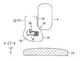
図1は、本実施形態のエアバッグ装置が適用される車両用シート(座席)11のシートバック(背もたれ部)12を示している。また、図2は、車両におけるシートバック12及びボディサイド部13の位置関係を示している。これらの図1及び図2の少なくとも一方に示すように、車両用シート11(シートバック12)は車両のドア等のボディサイド部13の車内側近傍に配置されている。
Hereinafter, an embodiment embodying the present invention will be described with reference to FIGS.
FIG. 1 shows a seat back (backrest portion) 12 of a vehicle seat (seat) 11 to which the airbag apparatus of the present embodiment is applied. Moreover, FIG. 2 has shown the positional relationship of the seat back 12 and the
なお、図1及び図2では、矢印Aで示す側が車外側を、矢印Bで示す側が車内側をそれぞれ指している。従って、矢印A,Bで示す方向が車幅方向となる。また、図1及び図2中、矢印Cで示す方向は、車両の進行方向前方(以下、単に「前方」という)を指している。他の図についても同様である。 1 and 2, the side indicated by the arrow A indicates the vehicle outer side, and the side indicated by the arrow B indicates the vehicle inner side. Accordingly, the direction indicated by arrows A and B is the vehicle width direction. 1 and 2, the direction indicated by the arrow C indicates the front of the vehicle in the traveling direction (hereinafter simply referred to as “front”). The same applies to other figures.
シートバック12は、その前部であって、車幅方向における両側部にサイドサポート部14,15を有している。両サイドサポート部14,15は、車両用シート11に着座してシートバック12にもたれた乗員Pの車幅方向の動きを規制するように乗員Pをサポートするためのものである。ここで、シートバック12において、車内側及び車外側の両側部を除く部分を中間部10とすると、両サイドサポート部14,15はこの中間部10の前面よりも前方へ張り出している。
The
次に、シートバック12において、サイドサポート部15を含む車外側の側部16の内部構造について説明する。
図3に示すように、シートバック12では、シートフレームが骨格とされ、その周りにウレタンフォーム等の弾性材からなるシートパッド21が設けられている。シートフレームの一部はシートバック12の側部16内に配置されており、この部分(以下、「サイドフレーム部22」という)は、本実施形態では金属板を曲げ加工することによって形成されている。サイドフレーム部22は、前後方向へ延びる側壁部23(図4参照)と、その側壁部23の後端から車内側へ折り曲げられた後壁部24とを備えている。
Next, in the seat back 12, the internal structure of the
As shown in FIG. 3, in the
シートパッド21は複数枚の表皮25〜27によって被覆されている。表皮26,27は、サイドサポート部15の側面前部において重ね合わされて縫合されている。この縫合部分28は、シートパッド21に設けられた溝部29に収容されている。縫合部分28は、両表皮26,27の非縫合部分よりも強度が低いことから、後述するエアバッグ44によって破断される破断予定部の一部を構成している。
The
また、図5に示すように、表皮25,26において、中間部10とサイドサポート部15との境界部17に対応する箇所は、後方へ折り曲げられて縫合されている。この縫合部分30は、後方へ引っ張られた状態で、シートパッド21の前部に設けられた溝部31内に収容されている。縫合部分30を後方へ引っ張った状態に保持するために、次の構成が採用されている。縫合部分30には布等からなるワイヤ取付け部32が共縫いされており、上下方向に延びる吊り込みワイヤ33がこのワイヤ取付け部32に挿入されている。また、上記溝部31の後方近傍には上下方向に延びるインサートワイヤ34がシートパッド21に埋設されている。そして、これらの吊り込みワイヤ33及びインサートワイヤ34は、上下方向についての複数箇所においてリング35をかしめることによって連結されている。リング35の材料としては金属が代表的である。なお、図5ではかしめる前の状態のリング35が図示されている。
Further, as shown in FIG. 5, in the
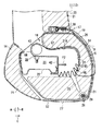
図3に示すように、シートパッド21についてサイドフレーム部22の近傍には、エアバッグ装置の主要部をなすエアバッグモジュール18を組み込むための収容空間が設けられている。この収容空間は、サイドフレーム部22よりも車内側の近傍部分に設けられた側部収容空間36と、サイドフレーム部22よりも前側の近傍部分に設けられた前部収容空間37とを有する。前部収容空間37は、側部収容空間36の前側に連続して形成されている。
As shown in FIG. 3, in the vicinity of the
ここで、前部収容空間37や、ここに収容されるエアバッグ44等は車両用シート11の座り心地(シートバック12のもたれ心地)を損なう要因となり得る。シートパッド21が設けられている場合よりも弾力性が低下するからである。そのため、前部収容空間37の大きさは、乗り心地等を大きく損なわないような大きさに制限されている。なお、側部収容空間36では、こうした大きさについての制限はほとんどない。
Here, the
前部収容空間37の車外側の角部からは、表皮26,27の縫合部分28に向けてスリット38が延びている。シートパッド21においてスリット38と縫合部分28との間の箇所は薄肉状をなしており、縫合部分28とともに上記破断予定部を構成している。
A
図3及び図4の少なくとも一方に示すように、サイドフレーム部22にはブラケット39が取り付けられている。ブラケット39は、サイドフレーム部22の側壁部23から車内側へ所定距離隔てた箇所で前後方向に延びる側板部41と、その側板部41の前端から車外側へ延びる前板部42とを備える。これらの側板部41及び前板部42はいずれも金属板等の剛性の高い板材によって形成されている。そして、ブラケット39は締結部品(図示略)等により、前板部42においてサイドフレーム部22の側壁部23の前端部に固定されている。なお、ブラケット39はサイドフレーム部22に一体形成されてもよい。また、サイドフレーム部22そのものがブラケット39を構成していてもよい。
As shown in at least one of FIGS. 3 and 4, a
エアバッグモジュール18は、ガス発生源としてのインフレータ43と、このインフレータ43を覆うように装着されたエアバッグ44とを備えている。インフレータ43の内部にはガス発生剤(図示略)が収容されている。このタイプのインフレータ43ではガス発生剤の燃焼反応によってガスが生成される。このタイプに代えて、高圧ガスの充填された高圧ガスボンベの隔壁を火薬等を用いて破ってガスを噴出させるタイプのインフレータが用いられてもよい。インフレータ43は上記ブラケット39の側板部41の車内側近傍に配置され、ボルト45、ナット46等の締結部品によってその側板部41の後端部に固定されている。
The
エアバッグ44は、例えば一対の基布をその周縁部を縫合することによって袋状に形成されている。エアバッグ44は、機能的には、斜め前方車内側へ向けて膨張展開する第1膨張展開部47と、前方へ向けて膨張展開する第2膨張展開部48とを備えて構成されている。第1膨張展開部47は、側部収容空間36中、インフレータ43よりも前方、かつ側板部41の車内側近傍において折り畳まれていない状態で配置されている。第2膨張展開部48は、前部収容空間37中、第1膨張展開部47よりも前方、かつ前板部42の前方近傍において折り畳まれた状態で配置されている。
The
上述したインフレータ43、エアバッグ44等は、合成樹脂等のケースには収容されておらず、可撓性を有する袋体(図示略)によって包み込まれている。
このようにしてエアバッグモジュール18が、シートバック12について車外側の側部16に組み込まれている。こうした態様でエアバッグモジュール18を組み込んだのは、シートバック12における車外側のサイドサポート部15について、その付け根部分19をエアバッグ44の膨張展開時に斜め前方車内側へ押圧するためである。ここでの付け根部分19は、図3において二点鎖線で示すように、車外側のサイドサポート部15についてエアバッグ44によって押圧される部分であって、エアバッグモジュール18と乗員Pとの間の部分である。より詳しくは、付け根部分19は、車幅方向については、サイドサポート部15において上記境界部17と第2膨張展開部48とによって挟まれた部分である。また、付け根部分19は、前後方向については、サイドサポート部15において中間部10の前面よりも前側の部分である。
The inflator 43, the
In this way, the
シートバック12内のエアバッグモジュール18と少なくとも付け根部分19との間には、エアバッグ44の膨張展開を妨げるような硬質物は何ら設けられていない。硬質物としては、例えばエアバッグ44の膨張展開方向を規制する補強部材等が挙げられる。一般的なサイドエアバッグ装置では、シートバックの側部内に収容されたエアバッグを斜め前方車外側へ確実に膨張展開させるべく、エアバッグを同方向へ導くための硬質の補強部材が設けられるところ、本実施形態ではこうした補強部材が設けられていない。なお、シートパッド21や、上述したエアバッグモジュール18を包み込む袋体は変形しやすく、この硬質物に該当しない。
Between the
こうした硬質物を設けない領域としては、エアバッグ44の膨張展開を妨げないという観点からは広い方が望ましく、境界部17と縫合部分28とによって挟まれた領域が、採り得る最も広い領域(最大領域)となる。この最大領域中、第2膨張展開部48よりも車外側の箇所は、一般的なサイドエアバッグ装置においても同様にエアバッグの膨張展開を妨げる硬質物が設けられない領域である。従って、上記最大領域は、一般的なサイドエアバッグ装置のそれよりも広くなる。また、サイドサポート部15についてエアバッグ44の膨張展開時に斜め前方車内側へ押圧される箇所(付け根部分19)は、硬質物が設けられない上記最大領域に含まれる。しかも、付け根部分19は、一般的なサイドエアバッグ装置において硬質物の設けられない上記領域よりも車内側に位置しており、エアバッグ44の膨張展開初期にはこの部分においてシートパッド21が押圧される。
The region where such a hard object is not provided is preferably wide from the viewpoint of not hindering the inflation and deployment of the
エアバッグ装置は、上述したエアバッグモジュール18のほかに図示しない衝撃センサ及び制御装置を備える。衝撃センサは加速度センサ等からなり、車両のボディサイド部13(図2参照)に設けられている。衝撃センサは、ボディサイド部13に側方から加えられる衝撃を検出する。制御装置は、衝撃センサによって検出された衝撃が所定値以上である場合にインフレータ43を作動させる。インフレータ43から高圧のガスがエアバッグ44内に噴出供給され、そのガスの圧力によってエアバッグ44が膨張展開される。
The airbag device includes an impact sensor and a control device (not shown) in addition to the
さらに、表皮26,27及びシートパッド21間であって、サイドフレーム部22、ブラケット39及びエアバッグモジュール18の周りに対応する箇所には、エアバッグ44の展開性向上を目的として、伸びの少ない材料によってそれぞれ帯状に形成された2枚の力布51,52が巻き付けられている。各力布51,52の一方の端部は、上記縫合部分28において表皮26,27と共縫いされている。また、各力布51,52の他方の端部は上記サイドフレーム部22の後壁部24に係止されている。両力布51,52は、エアバッグ44の膨張展開初期に伸長した状態となることにより、所定の展開方向とは異なる方向へのエアバッグ44の膨張を抑制する。また、両力布51,52は、シートパッド21の変形や表皮26,27の伸びを抑制して破断予定部の破断のきっかけとする。
Furthermore, between the
上記のようにして本実施形態のエアバッグ装置が構成されている。このエアバッグ装置では、図3に示す状態において、車両側方からの衝撃に応じてインフレータ43から高圧のガスが噴出されると、そのガスにより、まずエアバッグ44の第1膨張展開部47が膨張し始める。この際、高い剛性を有するブラケット39の側板部41が第1受圧部として機能し、斜め後方車外側へ向かうガスの圧力を受け止めるとともに、斜め前方車内側へ向かう反力F1を発生させる。この反力F1により、第1膨張展開部47が斜め前方車内側へ確実にかつ速く膨張展開していき、側部収容空間36等においてシートパッド21の内面21Aに当接する。膨張が進行するに従い、第1膨張展開部47がシートパッド21を斜め前方車内側へ押圧する。
The airbag device of the present embodiment is configured as described above. In this airbag apparatus, when a high-pressure gas is ejected from the inflator 43 in response to an impact from the side of the vehicle in the state shown in FIG. 3, first, the first inflating and deploying
この押圧により、図6に示すように、サイドサポート部15における付け根部分19が斜め前方車内側へ膨らみ始める。この膨らんだサイドサポート部15により、車両用シート11に着座してシートバック12にもたれている乗員Pが押されて車内側へ移動させられる。この移動方向は、車両のボディサイド部13から遠ざかる方向である。
By this pressing, as shown in FIG. 6, the
ここで、仮にシートバック12内のエアバッグモジュール18と付け根部分19との間に硬質物が存在すると、エアバッグ44の膨張展開が硬質物によって妨げられる。エアバッグ44の膨張初期に付け根部分19が斜め前方車内側へ押圧されにくく、同付け根部分19が同方向へ膨らみ乗員Pを車内側へ押す効果が得られにくくなる。しかし、本実施形態では、こうした硬質物がエアバッグモジュール18及び付け根部分19間に設けられていない。そのため、エアバッグ44の膨張展開の初期段階から、サイドサポート部15の付け根部分19が斜め前方車内側へ確実に押圧される。
Here, if a hard object exists between the
また、仮に第1膨張展開部47が折り畳まれていると、その折り畳み部分は膨張展開の抵抗となる。この点、本実施形態では第1膨張展開部47が折り畳まれていない。このため、折り畳まれている場合よりも膨張展開の抵抗となる要素が少なく、第1膨張展開部47が速く膨張展開させられる。
Further, if the first inflating and unfolding
上記エアバッグ44では、インフレータ43から噴出される高圧のガスにより、第1膨張展開部47に加え、第2膨張展開部48もまた膨張し始める。ガスの圧力が第2膨張展開部48を通じてブラケット39の前板部42に加わる。この際、剛性の高い前板部42が第2受圧部として機能し、後方へ向かうガスの圧力を受け止めるとともに、前方へ向かう反力F2を発生させる。この反力F2により、第2膨張展開部48が前方へ確実にかつ速く膨張展開していき、前部収容空間37においてシートパッド21の内面21Bに当接する。膨張が進行するに従い、第2膨張展開部48がシートパッド21を前方へ押圧するとともに、同第2膨張展開部48の一部がスリット38内に進入していく。第2膨張展開部48は、スリット38内に充填された後も膨張展開し続けようとする。
In the
そのため、エアバッグ44(第1膨張展開部47及び第2膨張展開部48)の膨張の進行に伴いサイドサポート部15が、図7に示すように破断予定部において破断される。すなわち、スリット38と縫合部分28との間におけるシートパッド21の薄肉部分が破断されるとともに、同縫合部分28における縫合状態が解除されて開口49が生ずる。第1膨張展開部47及び第2膨張展開部48は破断により生じた上記開口49を拡大させつつ、その開口49を通じてシートバック12から飛び出す。このとき、サイドサポート部15において開口49よりも車内側の部分は、縫合部分30を支点として前方へ開く。また、サイドサポート部15において開口49よりも後ろ側の部分は、シートパッド21の側部に設けられた切欠き50を支点として後方へ開く。
Therefore, as the airbag 44 (the first inflating and deploying
その後も第1膨張展開部47は膨張展開し続け、図8において矢印Dで示すように乗員Pを直接車内側へ押圧する。なお、同図8中の二点鎖線はエアバッグ装置が作動する前の乗員Pの位置を示している。
Thereafter, the first inflating and deploying
このように本実施形態によると、エアバッグ44がシートバック12内で膨らんでいる膨張の初期段階から、乗員Pが車内側へ押される。膨張したエアバッグ44がシートバック12から飛び出した後に乗員Pを直接押す場合よりも早い時期から、乗員Pが車内側へ移動させられる。
As described above, according to the present embodiment, the occupant P is pushed to the inside of the vehicle from the initial stage of inflation in which the
また、縫合部分28等の破断に伴い生じた開口49から飛び出した第2膨張展開部48はシートバック12から前方へ膨張展開する。この膨張展開したエアバッグ44が、乗員P、特に肩から腰に掛けての広い箇所と、図8の矢印Eで示すように車室内に進入してくるボディサイド部13との間に介在し、ボディサイド部13を通じて乗員Pへ伝わる側方からの衝撃を緩和する。この際、上述したように予めサイドサポート部15により乗員Pが押されて車内側へ移動させられているため、ボディサイド部13から乗員Pに伝わる衝撃が和らげられる。
In addition, the second inflating / deploying
以上詳述した本実施形態によれば、次の効果が得られる。
(1)シートバック12における車外側のサイドサポート部15についてその付け根部分19がエアバッグ44の膨張展開時に斜め前方車内側へ押圧されるように、エアバッグモジュール18をシートバック12内に組み込んでいる。このため、エアバッグ44がシートバック12内で膨らむ膨張の初期段階から乗員Pを車内側へ押すことができる。膨張したエアバッグ44がシートバック12から飛び出した後に乗員Pを直接押す場合よりも早い時期から、乗員Pを車内側へ移動させることができ、車両側方からの衝撃に対する乗員Pの保護性能をさらに向上させることができる。
According to the embodiment described in detail above, the following effects can be obtained.
(1) The
(2)エアバッグ44の膨張初期については、上記(1)のように弾性材からなるシートバック12(シートパッド21)を介して乗員Pを車内側へ押すようにしている。そのため、エアバッグ44自体によるよりも乗員Pをソフトに押すことができる。
(2) In the initial stage of inflation of the
(3)シートバック12内のエアバッグモジュール18とサイドサポート部15の付け根部分19との間に、エアバッグ44の膨張展開を妨げるような硬質物を何ら設けていない。そのため、エアバッグ44の膨張展開の初期段階から、付け根部分19を斜め前方車内側へ押圧することが可能となり、上記(1)に記載の効果を確実に得ることができる。
(3) No hard object is provided between the
(4)エアバッグ44に、斜め前方車内側へ向けて膨張展開する第1膨張展開部47と、前方へ向けて膨張展開する第2膨張展開部48とを設けている。このため、第1膨張展開部47の膨張展開により、上記(1)に記載の効果を得ることができる。これに加えて、第2膨張展開部48の膨張展開により、ボディサイド部13を通じて乗員Pへ伝わる側方からの衝撃を緩和することができる。このときには、第1膨張展開部47の膨張展開によって乗員が車内側へ既に移動させられている。従って、両膨張展開部47,48の膨張展開により、車両に対する側方からの衝撃を一層効果的に緩和することができる。
(4) The
(5)シートバック12内であって第1膨張展開部47の車外側近傍にブラケット39の側板部41を設け、これを第1受圧部として機能させるようにしている。そのため、側板部41により、膨張する第1膨張展開部47を通じてガスの圧力を受け、同第1膨張展開部47に斜め前方車内側へ向かう反力F1を作用させることができる。従って、こうした第1受圧部の設けられていない場合に比べ、第1膨張展開部47を斜め前方車内側へ確実にかつ速く膨張展開させて、サイドサポート部15の付け根部分19を斜め前方車内側へ押圧することができる。
(5) A
(6)第1膨張展開部47を折り畳まずにシートバック12内に組み込んでいる。このため、折り畳んだ場合よりも膨張展開の抵抗となる要素を少なくし、第1膨張展開部47を速く膨張展開させ、乗員Pをより早い時期から車内側へ押圧することができる。
(6) The first inflating and deploying
(7)シートバック12内であって第2膨張展開部48の後方近傍にブラケット39の前板部42を設け、これを第2受圧部として機能させるようにしている。そのため、前板部42により、膨張する第2膨張展開部48を通じてガスの圧力を受け、同第2膨張展開部48に対し前方へ向かう反力F2を作用させることができる。従って、こうした第2受圧部が設けられていない場合に比べ、第2膨張展開部48を前方へ確実にかつ速く膨張展開させることができる。
(7) A
(8)車両用シート11の乗り心地を確保する観点からは、サイドフレーム部22の前方に大きな前部収容空間37を設けることが困難である。この点、本実施形態では、第2膨張展開部48を折り畳むことによりコンパクトにしている。そのため、上記のように前部収容空間37が大きくなくても第2膨張展開部48を確実に組み込むことができる。
(8) From the viewpoint of securing the riding comfort of the
なお、本発明は次に示す別の実施形態に具体化することができる。
・本発明のエアバッグ装置は、上記実施形態とは異なる形状を有するサイドフレーム部22が用いられた車両用シートにも適用可能である。図9〜図11は、その一態様を示している。
Note that the present invention can be embodied in another embodiment described below.
-The airbag apparatus of this invention is applicable also to the vehicle seat in which the
図9及び図10のサイドフレーム部22では、側壁部23の前端から車内側に延びる前壁部53が設けられている。この場合、上記実施形態と同様の構成を有するブラケット39をサイドフレーム部22に取り付けるとともに、インフレータ43及び第1膨張展開部47を側板部41の車内側近傍に配置し、第2膨張展開部48を前板部42の前方近傍に配置してもよい。
9 and 10, a
図10では、図9よりも側壁部23の前後長の長いサイドフレーム部22が用いられている。これに伴い、図9ではインフレータ43がサイドフレーム部22の後壁部24よりも後方に配置されているのに対し、図10ではインフレータ43が同後壁部24よりも前方に配置されている。
In FIG. 10, the
また、図11ではサイドフレーム部22が円管状をなしている。この場合、インフレータ43及びエアバッグ44を、ブラケット39を介してサイドフレーム部22に取り付けてもよい。ブラケット39は、前後方向に延びる側板部54と、その側板部54の後端から車内側へ延びる後板部55と、側板部54の前端から車外側へ延びる前板部56とを有する。そして、ブラケット39をその後板部55においてサイドフレーム部22に固定する。さらに、インフレータ43及び第1膨張展開部47を側板部54の車内側近傍に配置し、第2膨張展開部48を前板部56の前方近傍に配置してもよい。
In FIG. 11, the
・図12に示すように、エアバッグモジュール18をサイドフレーム部22に直接取付けてもよい。
サイドフレーム部22が、前記実施形態と同様に側壁部23及び後壁部24を備えるものである場合には、高い剛性を有する側壁部23は、第1膨張展開部47の車外側近傍に位置することから第1受圧部として機能する。この機能発揮により、側壁部23は、膨張する第1膨張展開部47を通じてガスの圧力を受け、斜め前方車内側へ向かう反力を発生させる。
As shown in FIG. 12, the
In the case where the
また、高い剛性を有する側壁部23の前端部は、第2膨張展開部48の後側近傍に位置することから第2受圧部として機能する。この機能発揮により、側壁部23の前端が、膨張する第2膨張展開部48を通じてガスの圧力を受け、前方へ向かう反力を発生させる。そのため、第1受圧部及び第2受圧部を別途設けなくても上記実施形態と同様の効果が得られる。
Further, since the front end portion of the
・エアバッグ44における第2膨張展開部48を割愛してもよい。この場合、第1膨張展開部47のみによってエアバッグ44を構成することとなる。これに伴い第2受圧部が不要となる。この場合にも、サイドサポート部15により乗員Pが押されて車内側へ移動させられる。そのため、進入してくるボディサイド部13と乗員Pとの干渉を抑制し、その干渉に伴う衝撃を和らげることができる。
-You may omit the 2nd expansion |
・第1膨張展開部47を折り畳んだ状態でシートバック12に組み込んでもよい。また、第2膨張展開部48を折り畳まない状態でシートバック12に組み込んでもよい。
・本発明は、乗員Pについて上記実施形態とは異なる部位を保護するエアバッグ装置にも適用可能である。
-You may incorporate in the seat back 12 in the state which the 1st expansion | deployment expansion |
-This invention is applicable also to the airbag apparatus which protects the site | part different from the said embodiment about the passenger | crew P. FIG.
11…車両用シート、12…シートバック、14,15…サイドサポート部、16…側部、18…エアバッグモジュール、19…付け根部分、22…サイドフレーム部、41…側板部(第1受圧部)、42…前板部(第2受圧部)、43…インフレータ(ガス発生源)、44…エアバッグ、47…第1膨張展開部、48…第2膨張展開部、F1,F2…反力。
DESCRIPTION OF
Claims (1)
前後方向に延びる側板部、及び同側板部の前端から車外側へ延びる前板部を備えてなるブラケットが、前記シートバックの車外側の側部内に配置されており、
前記エアバッグの一部をなす第1膨張展開部は、折り畳まれていない状態で前記側板部の車内側近傍に配置され、
前記エアバッグの一部をなす第2膨張展開部は、折り畳まれた状態で前記前板部の前方近傍に配置されており、
前記シートバックにおける車外側のサイドサポート部の付け根部分と、前記シートバック内の前記エアバッグモジュールとの間には、前記エアバッグの膨張展開方向を規制する補強部材としての硬質物が設けられておらず、
前記側板部が、膨張する前記第1膨張展開部を通じてガスの圧力を受け、斜め前方車内側へ向かう反力を発生させる第1受圧部として機能することにより、前記第1膨張展開部を斜め前方車内側へ向けて膨張展開させて前記付け根部分を斜め前方車内側へ押圧し、
前記前板部が、膨張する前記第2膨張展開部を通じてガスの圧力を受け、前方へ向かう反力を発生させる第2受圧部として機能することにより、前記第2膨張展開部を車両前方へ向けて膨張展開させるようにしたことを特徴とするエアバッグ装置。 An airbag module comprising a gas generation source that generates gas in response to an impact from the side of the vehicle and an airbag that is inflated and deployed by the gas from the gas generation source is provided on the outside of the vehicle with respect to the seat back of the vehicle seat. An airbag device incorporated in a side part,
A bracket comprising a side plate portion extending in the front-rear direction and a front plate portion extending from the front end of the same side plate portion to the vehicle outer side is disposed in the side portion on the vehicle outer side of the seat back,
The first inflating and deploying portion forming a part of the airbag is disposed in the vicinity of the vehicle interior side of the side plate portion in an unfolded state,
The second inflating and deploying part forming a part of the airbag is arranged in the vicinity of the front of the front plate part in a folded state,
Between the base portion of the side support portion on the vehicle outer side in the seat back and the airbag module in the seat back, a hard material is provided as a reinforcing member that regulates the inflation and deployment direction of the airbag. Without
The side plate portion functions as a first pressure receiving portion that receives a gas pressure through the first inflating and expanding portion that expands and generates a reaction force toward the inside of the diagonally forward vehicle. Inflate and deploy toward the inside of the car and press the base part diagonally forward to the inside of the car,
The front plate portion functions as a second pressure receiving portion that receives a gas pressure through the second inflating and expanding portion that expands and generates a reaction force toward the front, thereby causing the second inflating and expanding portion to face the front of the vehicle. An airbag apparatus characterized by being inflated and deployed.
Priority Applications (3)
| Application Number | Priority Date | Filing Date | Title |
|---|---|---|---|
| JP2006146894A JP4760533B2 (en) | 2006-05-26 | 2006-05-26 | Airbag device |
| US11/802,280 US7695004B2 (en) | 2006-05-26 | 2007-05-22 | Airbag apparatus |
| DE102007000291A DE102007000291A1 (en) | 2006-05-26 | 2007-05-25 | Airbag device for reducing impact from a vehicle's side has an airbag subassembly built into a vehicle seat's backrest with side supports |
Applications Claiming Priority (1)
| Application Number | Priority Date | Filing Date | Title |
|---|---|---|---|
| JP2006146894A JP4760533B2 (en) | 2006-05-26 | 2006-05-26 | Airbag device |
Publications (3)
| Publication Number | Publication Date |
|---|---|
| JP2007314075A JP2007314075A (en) | 2007-12-06 |
| JP2007314075A5 JP2007314075A5 (en) | 2008-08-14 |
| JP4760533B2 true JP4760533B2 (en) | 2011-08-31 |
Family
ID=38622372
Family Applications (1)
| Application Number | Title | Priority Date | Filing Date |
|---|---|---|---|
| JP2006146894A Active JP4760533B2 (en) | 2006-05-26 | 2006-05-26 | Airbag device |
Country Status (3)
| Country | Link |
|---|---|
| US (1) | US7695004B2 (en) |
| JP (1) | JP4760533B2 (en) |
| DE (1) | DE102007000291A1 (en) |
Families Citing this family (35)
| Publication number | Priority date | Publication date | Assignee | Title |
|---|---|---|---|---|
| WO2006133739A1 (en) * | 2005-06-17 | 2006-12-21 | Dalphi Metal España, S.A. | Automotive vehicle seat with an airbag in the backrest thereof |
| JP5128229B2 (en) * | 2007-10-04 | 2013-01-23 | 本田技研工業株式会社 | Bracket for vehicle |
| WO2010003407A1 (en) * | 2008-07-10 | 2010-01-14 | Inova Gmbh | Airbag module and seat related thereto, and also manufacturing apparatus and assembly method therefore |
| JP5330758B2 (en) * | 2008-08-11 | 2013-10-30 | トヨタ自動車株式会社 | Seat back structure |
| JP4877350B2 (en) * | 2009-03-27 | 2012-02-15 | 豊田合成株式会社 | Side airbag device |
| DE102009016666A1 (en) * | 2009-03-31 | 2010-10-07 | Dr. Ing. H.C. F. Porsche Aktiengesellschaft | vehicle seat |
| DE102009016888A1 (en) * | 2009-04-08 | 2010-10-14 | GM Global Technology Operations, Inc., Detroit | Side protection airbag arrangement for vehicle, has vehicle seat, which has seat frame, and airbag module with airbag |
| WO2010131322A1 (en) * | 2009-05-11 | 2010-11-18 | トヨタ自動車株式会社 | Vehicle seat |
| JP5471026B2 (en) * | 2009-05-14 | 2014-04-16 | トヨタ紡織株式会社 | Vehicle seat with side airbag device |
| US20100295282A1 (en) * | 2009-05-21 | 2010-11-25 | Hyundai Motor Company | Seat with side airbag for vehicles |
| JP5476968B2 (en) * | 2009-12-11 | 2014-04-23 | トヨタ紡織株式会社 | Vehicle seat |
| US8955907B2 (en) | 2010-12-24 | 2015-02-17 | Ts Tech Co., Ltd. | Vehicle seat |
| JP5669567B2 (en) * | 2010-12-24 | 2015-02-12 | テイ・エス テック株式会社 | Vehicle seat |
| KR101283698B1 (en) * | 2011-03-29 | 2013-07-05 | 기아자동차주식회사 | Side air-bag for a vehicle |
| US8353526B2 (en) * | 2011-04-01 | 2013-01-15 | Lear Corporation | Air bag assembly with air bag guide secured by multiple fasteners |
| DE102012009886B4 (en) | 2011-06-08 | 2023-11-30 | Zf Automotive Germany Gmbh | Gas bag package for a side gas bag protection device integrated into a vehicle seat and vehicle seat with integrated gas bag package |
| EP2567870B1 (en) * | 2011-09-09 | 2015-03-25 | Autoliv Development AB | Vehicle seat with an airbag unit |
| CN104507760B (en) * | 2012-07-25 | 2018-01-12 | 丰田自动车株式会社 | The expansion direction limiting structure of side airbag |
| JP5942772B2 (en) * | 2012-10-18 | 2016-06-29 | トヨタ自動車株式会社 | Vehicle seat with side airbag device |
| JP6139956B2 (en) * | 2013-04-18 | 2017-05-31 | テイ・エス テック株式会社 | Vehicle seat |
| EP2939886B1 (en) | 2012-12-28 | 2018-12-05 | TS Tech Co., Ltd. | Airbag module-equipped seat, and method for mounting same |
| JP6098409B2 (en) * | 2013-07-19 | 2017-03-22 | 豊田合成株式会社 | Side airbag device |
| KR102269369B1 (en) * | 2014-11-17 | 2021-06-25 | 현대모비스 주식회사 | Installation structure of side airbag |
| JP5932007B2 (en) * | 2014-12-16 | 2016-06-08 | テイ・エス テック株式会社 | Vehicle seat |
| KR102083142B1 (en) * | 2016-09-05 | 2020-03-02 | 현대모비스 주식회사 | Curtain airbag apparatus |
| JP6610493B2 (en) | 2016-10-03 | 2019-11-27 | トヨタ自動車株式会社 | Vehicle seat with side airbag device |
| EP3549830B1 (en) * | 2016-12-05 | 2024-09-18 | Autoliv Development AB | Side air bag device |
| JP6658585B2 (en) * | 2017-02-03 | 2020-03-04 | トヨタ自動車株式会社 | Vehicle seats equipped with side airbag devices |
| JP6725193B2 (en) * | 2017-02-21 | 2020-07-15 | ダイハツ工業株式会社 | Side airbag device |
| JP6919383B2 (en) * | 2017-07-18 | 2021-08-18 | トヨタ自動車株式会社 | Vehicle seats equipped with side airbag devices |
| DE102017213855A1 (en) | 2017-08-09 | 2019-02-14 | Volkswagen Aktiengesellschaft | Safety device for a vehicle seat of a motor vehicle with an airbag |
| CN113423617B (en) * | 2018-12-21 | 2023-05-02 | 奥托立夫开发公司 | Side airbag device, method for manufacturing same, and vehicle seat provided with same |
| JP7180456B2 (en) * | 2019-03-06 | 2022-11-30 | トヨタ自動車株式会社 | Seat structure with far side airbag device |
| EP4218495A1 (en) * | 2019-04-17 | 2023-08-02 | Autoliv Development AB | Side airbag device |
| KR102625278B1 (en) * | 2019-05-31 | 2024-01-16 | 아우토리브 디벨롭먼트 아베 | Side airbag device and method of manufacturing the side airbag device |
Family Cites Families (11)
| Publication number | Priority date | Publication date | Assignee | Title |
|---|---|---|---|---|
| JP3712081B2 (en) * | 1996-01-31 | 2005-11-02 | マツダ株式会社 | Vehicle airbag device |
| JP3358450B2 (en) * | 1996-07-09 | 2002-12-16 | 三菱自動車工業株式会社 | Car seats |
| JP3642893B2 (en) | 1996-09-06 | 2005-04-27 | 株式会社タチエス | Seat pad structure for seat with built-in side airbag |
| JP3649820B2 (en) | 1996-09-06 | 2005-05-18 | 株式会社タチエス | Trim cover structure for seat with built-in side airbag. |
| JPH1134786A (en) * | 1997-07-17 | 1999-02-09 | Toyoda Gosei Co Ltd | Air bag device for side collision |
| US6450528B1 (en) * | 1998-10-01 | 2002-09-17 | Toyota Jidosha Kabushiki Kaisha | Vehicle seat housing an airbag device |
| US6213498B1 (en) * | 1999-03-10 | 2001-04-10 | Toyota Technical Center Usa, Inc. | Seat back air bag deployment system |
| US6352304B1 (en) * | 1999-08-19 | 2002-03-05 | Johnson Controls Technology Company | Device for indicating an airbag module position |
| JP2004017927A (en) * | 2002-06-20 | 2004-01-22 | Shigeru Co Ltd | Seat back for vehicle |
| US7134685B2 (en) * | 2004-01-16 | 2006-11-14 | Lear Corporation | Air bag deployment arrangement |
| JP4691727B2 (en) * | 2006-03-29 | 2011-06-01 | ダイハツ工業株式会社 | Seat with built-in side airbag |
-
2006
- 2006-05-26 JP JP2006146894A patent/JP4760533B2/en active Active
-
2007
- 2007-05-22 US US11/802,280 patent/US7695004B2/en active Active
- 2007-05-25 DE DE102007000291A patent/DE102007000291A1/en active Pending
Also Published As
| Publication number | Publication date |
|---|---|
| US7695004B2 (en) | 2010-04-13 |
| JP2007314075A (en) | 2007-12-06 |
| DE102007000291A1 (en) | 2007-11-29 |
| US20070273129A1 (en) | 2007-11-29 |
Similar Documents
| Publication | Publication Date | Title |
|---|---|---|
| JP4760533B2 (en) | Airbag device | |
| JP4187721B2 (en) | Improved vehicle seat | |
| JP4952422B2 (en) | Side airbag device | |
| JP5035004B2 (en) | Side airbag device | |
| JP6435412B2 (en) | Crew protection device | |
| JP5003299B2 (en) | Side airbag device | |
| JP6748294B2 (en) | Occupant protection device | |
| JP4816387B2 (en) | Side airbag device | |
| JP4962185B2 (en) | Side airbag device | |
| JP5572348B2 (en) | Roof airbag device for vehicle | |
| CN111918795B (en) | Side airbag device and vehicle seat having the same | |
| JP2008174137A (en) | Side airbag device | |
| US20220055570A1 (en) | Side airbag device, vehicle seat provided with same, and method for manufacturing side airbag device | |
| JP5907135B2 (en) | Side airbag device for vehicle | |
| JP2018052275A (en) | Airbag device for vehicle and wrapping material used therefor | |
| JP2019147426A (en) | Vehicle occupant protection device | |
| WO2019138954A1 (en) | Occupant protection apparatus | |
| CN110603174A (en) | Side airbag device | |
| JP6067489B2 (en) | Side airbag device | |
| JP2019137100A (en) | Side airbag device | |
| JP2008137458A (en) | Airbag device | |
| JP2010155575A (en) | Occupant crash protection device and vehicle | |
| JP5365433B2 (en) | Airbag device for passenger seat | |
| JP4640325B2 (en) | Side airbag device for vehicle | |
| JP6995210B2 (en) | Side airbag device |
Legal Events
| Date | Code | Title | Description |
|---|---|---|---|
| A521 | Written amendment |
Free format text: JAPANESE INTERMEDIATE CODE: A523 Effective date: 20080627 |
|
| A621 | Written request for application examination |
Free format text: JAPANESE INTERMEDIATE CODE: A621 Effective date: 20080821 |
|
| A977 | Report on retrieval |
Free format text: JAPANESE INTERMEDIATE CODE: A971007 Effective date: 20101117 |
|
| A131 | Notification of reasons for refusal |
Free format text: JAPANESE INTERMEDIATE CODE: A131 Effective date: 20101130 |
|
| A521 | Written amendment |
Free format text: JAPANESE INTERMEDIATE CODE: A523 Effective date: 20110128 |
|
| TRDD | Decision of grant or rejection written | ||
| A01 | Written decision to grant a patent or to grant a registration (utility model) |
Free format text: JAPANESE INTERMEDIATE CODE: A01 Effective date: 20110510 |
|
| A61 | First payment of annual fees (during grant procedure) |
Free format text: JAPANESE INTERMEDIATE CODE: A61 Effective date: 20110523 |
|
| FPAY | Renewal fee payment (event date is renewal date of database) |
Free format text: PAYMENT UNTIL: 20140617 Year of fee payment: 3 |
|
| R150 | Certificate of patent or registration of utility model |
Ref document number: 4760533 Country of ref document: JP Free format text: JAPANESE INTERMEDIATE CODE: R150 Free format text: JAPANESE INTERMEDIATE CODE: R150 |