JP4816387B2 - Side airbag device - Google Patents
Side airbag device Download PDFInfo
- Publication number
- JP4816387B2 JP4816387B2 JP2006270867A JP2006270867A JP4816387B2 JP 4816387 B2 JP4816387 B2 JP 4816387B2 JP 2006270867 A JP2006270867 A JP 2006270867A JP 2006270867 A JP2006270867 A JP 2006270867A JP 4816387 B2 JP4816387 B2 JP 4816387B2
- Authority
- JP
- Japan
- Prior art keywords
- airbag
- vehicle
- airbag device
- side airbag
- seat
- Prior art date
- Legal status (The legal status is an assumption and is not a legal conclusion. Google has not performed a legal analysis and makes no representation as to the accuracy of the status listed.)
- Active
Links
Images


Description
本発明は、車室に配設されたシートのシートバックに設けられた膨張部をシートに着座する乗員と車両側壁との間において膨張展開させるサイドエアバッグ装置に関する。 The present invention relates to a side airbag device that inflates and deploys an inflatable portion provided on a seat back of a seat disposed in a passenger compartment between an occupant seated on the seat and a vehicle side wall.
従来車両の乗員保護装置としては、例えば特許文献1に記載されるように、側突等、車両にその横方向から大きな衝撃力が作用した場合に、その衝撃から乗員を保護するようにしたサイドエアバッグ装置が知られている。このサイドエアバッグ装置においては、車両への衝撃の検知を契機にインフレータからガスが発生し、この発生したガスがシートのシートバックに設けられたエアバッグに流入することによりエアバッグが膨張を開始する。そして、この膨張したエアバッグがシートバックから車両側壁とシートに着座した乗員との間の空間に展開される。
このように、従来のサイドエアバッグ装置にあっては、シートに着座した乗員と車両側壁との間の僅かな空間において膨張展開させる必要がある。ここで、例えば乗員がシートにおいて車両側壁寄りに着座している場合、或いはシートに着座した乗員の体格が標準的な大人の体格を大きく上回っているような場合等には、このエアバッグが膨張展開し得る空間が更に狭められることとなる。その結果、従来のエアバッグ装置にあっては、このような場合にエアバッグを膨張展開させる際の迅速性および確実性を確保することが困難になるおそれがあり、このような点でなお改善の余地を残すものとなっていた。 Thus, in the conventional side airbag apparatus, it is necessary to inflate and deploy in a slight space between the occupant seated on the seat and the vehicle side wall. Here, for example, when the occupant is seated near the vehicle side wall in the seat, or when the physique of the occupant seated on the seat is significantly higher than the standard adult physique, the airbag is inflated. The space that can be developed is further narrowed. As a result, in the conventional airbag device, it may be difficult to ensure the speed and certainty when inflating and deploying the airbag in such a case, and this point is still an improvement. The room was left.
本発明は、上記課題に鑑みてなされたものであり、その目的は、シートに着座した乗員と車両側壁との間にエアバッグを膨張展開させるサイドエアバッグ装置において、エアバッグの膨張展開可能な空間を広く確保してその膨張展開を迅速かつ確実に行うことの可能なサイドエアバッグ装置を提供することにある。 The present invention has been made in view of the above problems, and an object of the present invention is to enable the airbag to be inflated and deployed in a side airbag device that inflates and deploys an airbag between an occupant seated on a seat and a vehicle side wall. It is an object of the present invention to provide a side airbag device capable of securing a wide space and inflating and deploying it quickly and reliably.
上記課題を解決するために、請求項1に記載の発明は、車室に配設されるシートのシートバックに設けられた主膨張部が前記シートに着座する乗員と車両側壁との間で膨張展開するサイドエアバッグ装置において、前記シートバック内の前記主膨張部よりも車内側に偏倚した位置には、該主膨張部が膨張展開する際に膨張展開する補助膨張部が設けられ、前記主膨張部は、前記シートバックを破断して前記車室内に膨張展開し、前記補助膨張部は、前記シートバックを変形させながら該シートバックを介して前記シートに着座する乗員の上半身を車両斜め前方の車内側に押圧して膨張展開することをその要旨とする。 In order to solve the above problems, a first aspect of the present invention, the expansion between the vehicle occupant and the vehicle sidewall main expansion portion provided in a seat back of a seat disposed in the vehicle compartment is seated on the seat in the side airbag device that expand, in the main than expanding portion and biased inside the vehicle position within said seat back, the auxiliary inflatable portion main inflation portion is inflated and deployed when inflated and deployed is provided, wherein The main inflating portion breaks the seat back and inflates and deploys in the passenger compartment, and the auxiliary inflating portion deforms the seat back and deforms the upper body of an occupant seated on the seat via the seat back. The gist is to inflate and deploy by pressing toward the front vehicle interior.
同構成によれば、主膨張部の膨張展開に際し、該主膨張部よりも早い時期にインフレータから補助膨張部にガスが流入して、該補助膨張部が膨張展開する。この補助膨張部の膨張展開によって乗員の上半身が車内側に変位するようになるため、乗員と車両側壁との間の空間が広くなる。この空間の拡大後に主膨張部が膨張展開するようになる。したがって、このように広くなった空間においては、主膨張部がその膨張展開の際に乗員と側壁とによって挟まれて膨張が妨げられることが抑制されるため、主膨張部をより確実かつ迅速に膨張展開させることができるようになる。従って、例えば乗員の腰を押圧するようにした構成と比較して、乗員と車両側壁との間の空間をより迅速に拡大させることができ、この点において主膨張部のより確実かつ迅速な膨張展開に寄与することができるようになる。 According to this configuration, when the main inflating portion is inflated and deployed, gas flows from the inflator to the auxiliary inflating portion earlier than the main inflating portion, and the auxiliary inflating portion is inflated and deployed. Since the expansion exhibition therefore the upper body of the occupant to open the auxiliary inflatable portion comes to be displaced inside the vehicle, the space between the occupant and the vehicle sidewall wider. After the expansion of the space, the main expansion part expands and deploys. Therefore, in such a wide space, the main inflating portion is prevented from being hindered from being inflated by being sandwiched between the occupant and the side wall at the time of inflating and deploying. It can be inflated and deployed. Therefore, for example, the space between the occupant and the vehicle side wall can be expanded more quickly than in the configuration in which the occupant's waist is pressed, and in this respect, the main expansion portion can be more reliably and quickly expanded. It will be possible to contribute to the development.
なお、このような補助膨張部としては、請求項2に記載されるように、これを主膨張部とは別の独立したものとする構成や、請求項3に記載されるように、共通のエアバッグの内部を区画形成することにより主膨張部とは別の膨張空間とする構成を採用することができる。 In addition, as such an auxiliary | assistant expansion | swelling part, as described in Claim 2, the structure which makes this independent from the main expansion | swelling part, and as described in Claim 3, it is common. It is possible to adopt a configuration in which the interior of the airbag is partitioned to form an inflatable space different from the main inflatable portion.
請求項4に記載の発明は、請求項2又は請求項3に記載のサイドエアバッグ装置において、前記補助膨張部は前記主膨張部よりもその容積が小さく設定されてなることをその要旨とする。 The gist of the invention according to claim 4 is that, in the side airbag device according to claim 2 or claim 3, the volume of the auxiliary inflation portion is set smaller than that of the main inflation portion. .
補助膨張部は乗員を押圧して変位させるためにその内圧が高く設定されることが望ましく、一方、主膨張部は乗員を受け止めるために可能な限り大きく展開されるようその大きさが設定されることが望ましい。この点上記構成によれば、限られた膨張のための空間において主膨張部の展開範囲を確保するとともに、補助膨張部の内圧を高めることができる。 It is desirable that the auxiliary inflating portion is set to have a high internal pressure in order to press and displace the occupant, while the main inflating portion is sized to be expanded as much as possible to catch the occupant. It is desirable. In this regard, according to the above configuration, the expansion range of the main expansion portion can be secured in the limited space for expansion, and the internal pressure of the auxiliary expansion portion can be increased.
なお、主膨張部よりも早い時期にインフレータから補助膨張部にガスを流入させて膨張展開させるためには例えば請求項5に記載の構成が採用可能である。すなわち、請求項5に記載の発明は、請求項1〜4のいずれか一項に記載のサイドエアバッグ装置において、前記主膨張部は、衝撃検知センサによる車両への衝突の検知を契機に膨張が開始されるとともに、前記補助膨張部は、車両への衝突を衝突前に検知するプリクラッシュセンサによる検知を契機に膨張が開始されることをその要旨とする。 In order to inflate and expand the gas by flowing the gas from the inflator to the auxiliary inflating part earlier than the main inflating part , for example, the configuration described in claim 5 can be adopted. That is, according to a fifth aspect of the present invention, in the side airbag device according to any one of the first to fourth aspects, the main inflating portion is inflated upon detection of a collision with a vehicle by an impact detection sensor. The gist of the auxiliary inflating section is that the expansion is started in response to detection by a pre-crash sensor that detects a collision with the vehicle before the collision.
請求項6に記載の発明は、請求項1〜5のいずれか一項に記載のサイドエアバッグ装置において、前記補助膨張部は、インフレータから流入されるガスの流入速度が、前記主膨張部に流入されるガスの流入速度より速く設定されてなることをその要旨とする。 According to a sixth aspect of the present invention, in the side airbag device according to any one of the first to fifth aspects, the auxiliary inflating portion has an inflow rate of gas flowing in from an inflator to the main inflating portion. The gist is that it is set faster than the inflow speed of the inflowing gas.
同構成によれば、主膨張部の膨張展開に際してより早期に補助膨張部を膨張展開させて乗員を車内側に変位させることが可能となり、それぞれの膨張部に対するガスの流入速度を同じ速度に設定した場合と比べて主膨張部が膨張展開するためにより広い空間を確保することができるようになる。 According to this configuration, it is possible to inflate and deploy the auxiliary inflatable part earlier when the main inflating part is inflated and to displace the occupant to the inside of the vehicle, and set the gas inflow speed to each inflating part to the same speed. Compared to the case, the main inflating part is inflated and deployed, so that a wider space can be secured.
請求項7に記載の発明は、請求項1〜6のいずれか一項に記載のサイドエアバッグ装置において、前記補助膨張部は、前記シートに着座した乗員の肩部から腹部にかかる部位を車両後方から押圧し得る位置に膨張展開するように前記シートバック内に設けられることをその要旨とする。 Invention according to claim 7, in the side airbag apparatus according to any one of claims 1 to 6, wherein the auxiliary expansion portion, vehicle parts according to the abdomen from the occupant of the shoulder seated on the seat The gist of the invention is that it is provided in the seat back so as to expand and deploy at a position where it can be pressed from behind.
同構成によれば、シートに着座している乗員の肋骨を横側や前側から押圧することを抑制することができ、補助膨張部をより適切に膨張させることができるようになる。 According to this configuration, it is possible to suppress pressing of the ribs of the occupant seated on the seat from the lateral side or the front side, and the auxiliary expansion portion can be expanded more appropriately.
本発明のサイドエアバッグ装置においては、エアバッグの膨張展開可能な空間を広く確保してその膨張展開を迅速かつ確実に行うことができるようになる。 In the side airbag device of the present invention, a wide space in which the airbag can be inflated and deployed can be secured, and the inflation and deployment can be performed quickly and reliably.
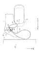
以下、本発明にかかるサイドエアバッグ装置の一実施形態について、図1〜図4に基づいて説明する。図1は本実施形態にかかる車室内においてサイドエアバッグ装置のエアバッグが膨張展開した状態をシートおよびシートに着座している乗員とともに示したものである。また、図2はこのサイドエアバッグ装置のエアバッグがシートバック内に収容された状態を、そのシートバック内部の構成と共々示す断面図である。なお、以下の記載において、車両の前進方向を前方(車両前方)として説明し、車両の後進方向を後方(車両後方)として説明する。また、以下の記載における上下方向は車両の上下方向、左右方向は車両の車幅方向であって車両前進時の左右方向と一致するものとする。 Hereinafter, an embodiment of a side airbag device according to the present invention will be described with reference to FIGS. FIG. 1 shows a state in which an airbag of a side airbag device is inflated and deployed in a vehicle interior according to the present embodiment together with a seat and a passenger seated on the seat. FIG. 2 is a cross-sectional view showing a state in which the airbag of the side airbag device is accommodated in the seat back together with the configuration inside the seat back. In the following description, the forward direction of the vehicle will be described as the front (front of the vehicle), and the reverse direction of the vehicle will be described as the rear (rear of the vehicle). Further, in the following description, the vertical direction is the vertical direction of the vehicle, and the horizontal direction is the vehicle width direction of the vehicle, which coincides with the horizontal direction when the vehicle is moving forward.
図1に示されるように、車室内にはシート10が設けられている。このシート10は、乗員Pの背もたれとなるシートバック11および乗員Pの着座部であるシートクッション12とによって構成されている。このシートバック11は、その前部であって、車幅方向における両側部にサイドサポート部13有しており、両サイドサポート部13は、車両シート10に着座してシートバック11にもたれた乗員Pの車幅方向の動きを規制するように乗員Pをサポートするためのものである。ここで、シートバック11において、車内側及び車外側の両側部を除く部分を中間部14とすると、両サイドサポート部13はこの中間部14の前面よりも前方へ張り出している。
As shown in FIG. 1, a
また、シートバック11の側部にはサイドエアバッグ装置20が内蔵されている。このサイドエアバッグ装置20は、衝撃検出部による車両の側部15への衝撃の検出を契機にインフレータ21(図2参照)から第1エアバッグ22内にガスを噴出させて、図1中において1点鎖線にて示すようにシート10に着座している乗員Pと車室内の側壁部16との間で同エアバッグ22を膨張展開させるように構成されている。このような態様で第1エアバッグ22が膨張展開されることで、乗員Pと上記側壁部16との接触が抑止され、乗員Pに対する衝撃も緩和されるようになる。
A
また、サイドエアバッグ装置20は、同じく衝撃検出部による車両の側壁部16への衝撃の検出を契機に第1エアバッグ22用のインフレータ21とは別のインフレータ23(図2参照)から第2エアバッグ24内にガスを噴出させて同エアバッグ24を膨張させる。そして、この膨張したエアバッグ24は、図1中に2点鎖線で示すようにシートバック11を変形させながら、同シートバック11を介して乗員Pを左側前方、すなわち車内側に押圧して変位させる。このような第2エアバッグ24の膨張により、第1エアバッグ22の展開スペース、すなわち乗員Pと側壁部16との間の空間が広くなり、第1エアバッグ22の展開性能の向上が図られている。
Further, the
以下、このようなサイドエアバッグ装置20の具体的な構成について、図2〜図4に基づいて説明する。なお、図3は、各エアバッグがシートバック内において膨張した状態を、そのシートバック内部の構成と共々示す断面図である。また図4は、第1エアバッグが車室内に膨張展開された状態をシートや車両の側壁部とともに示している。
Hereinafter, a specific configuration of such a
図2に示されるように、シートバック11では、シートフレームが骨格とされ、その周りにウレタンフォーム等の弾性材からなるシートパッド31が設けられている。シートフレームの一部はシートバック11のサイドサポート部13内に配置されており、この部分(以下、「サイドフレーム部32」という)は、本実施形態では金属板を曲げ加工することによって形成されている。サイドフレーム部32は、前後方向へ延びる側壁部33と、その側壁部33の後端から車内側へ折り曲げられた後壁部34とを備えている。
As shown in FIG. 2, in the
シートパッド31は複数枚の表皮35〜37によって被覆されており、表皮36,37は、サイドサポート部13の側面前部において重ね合わされて縫合されている。この縫合部分38は、シートパッド31に設けられた溝部39に収容されている。縫合部分38は、両表皮36,37の非縫合部分よりも強度が低く、第1エアバッグ22が膨張展開される際に破断されるように構成されている。
The
また、シートパッド31についてサイドフレーム部32の近傍には、上述した各エアバッグ22,24等を組み込むための収容空間が設けられている。この収容空間は、サイドフレーム部32よりも車内側(左方側)の部分に位置する側部収容空間41と、サイドフレーム部32よりも前側の部分に位置する前部収容空間42とを有している。前部収容空間42は、側部収容空間41の前側に位置して側部収容空間41から連続して形成されている。
The
前部収容空間42の車外側の角部からは、表皮36,37の縫合部分38に向けてスリット43が延びている。シートパッド31においてスリット43と縫合部分38との間の箇所は薄肉状に形成されることにより、縫合部分38とともに第1エアバッグ22の膨張に伴って破断されるように構成されている。
A
サイドフレーム部32にはブラケット44が取り付けられている。ブラケット44は、サイドフレーム部32の側壁部33から車内側へ所定距離隔てた箇所で前後方向に延びる側板部45と、その側板部45の前端から車外側へ延びる前板部46とを備える。これらの側板部45及び前板部46はいずれも金属板等の剛性の高い板材によって形成されている。そして、ブラケット44は前板部46においてサイドフレーム部32の側壁部33の前端部に固定されている。
A
そして、このように構成されたサイドフレーム部32には上述した各エアバッグ22,24がそれぞれ固定されている。より詳しくは、第1エアバッグ22の内部にはインフレータ21が収容されており、このインフレータ21は第1エアバッグ22共々側壁部33、すなわちサイドサポート部13の車外側の部位に対し固定されている。第1エアバッグ22は、その前方側の部位が折り畳まれた状態で収容されており、膨張に伴って折れ畳みが解除されて図2中にて矢印F1にて示す方向、すなわちシートパッド31に形成されたスリット43に向かって展開する。
And each
一方、第2エアバッグ24の内部にはインフレータ23が収容されており、このインフレータ23はブラケット44の側板部45の後端部、すなわちサイドサポート部13の車内側の部位にエアバッグ24共々固定されている。この第2エアバッグ24は、膨張に伴って図2中にて矢印F2にて示す方向に展開する。
On the other hand, an
このように構成された第1エアバッグ22及び第2エアバッグ24においては、その容量、すなわちガスの充填により膨張可能な体積が第2エアバッグ24の方が第1エアバッグ22よりも小さく設定されている。また、インフレータ21,23から各エアバッグ22,24に充填されるガスの流速(時間当たりの流量)は、インフレータ23の方がインフレータ21よりも速くなっている。これは、例えばインフレータ23の容量を大きくしたり、インフレータ23から第2エアバッグ24へのガスの流入経路となる部位の径を大きくしたりすることにより実現されている。
In the
また、サイドエアバッグ装置20は、衝撃検出部としての衝撃センサ及びプリクラッシュセンサ(図示略)を備えている。衝撃センサおよびプリクラッシュセンサは加速度センサ等からなり、車両の側部15(図1参照)に設けられている。衝撃センサは、側部15に側方から加えられる衝撃を検出し、この衝撃センサによって検出された衝撃が所定値以上である場合にインフレータ21が作動され第1エアバッグ22にガスが噴出される。一方、プリクラッシュセンサはいわゆるミリ波レーダ式のセンサであり、車両の側部15へ接近する他の車両を検出する。このプリクラッシュセンサにより、他の車両との衝突が回避不可能であると判定されるとインフレータ23が作動され第2エアバッグ24にガスが噴出される。
The
このように構成されたサイドエアバッグ装置20が作動すると、図3に示されるように、第1エアバッグ22は膨張展開して、スリット43を通じて縫合部分38を押圧し、サイドサポート部13を破断させる。そして、第1エアバッグ22は、この破断した部位から車室内に展開される。一方、第2エアバッグ24は左前方に向けて膨張されてシートパッド31をその内部から押圧する。この際この押圧力によりサイドサポート部13の形状が変形し、車両の内側に突出するようになり、乗員Pがこのサイドサポート部13によって車内側に押圧される。ちなみに、このとき第2エアバッグ24は、その膨張の大きさがシートクッション12に着座する乗員Pの肩部から腹部にかかる部位に対応するよう設定されており、乗員Pはこれらの部位が後方(斜め後方)から押圧される。すなわち図4に示されるように、第2エアバッグ24は2点鎖線にて示すようにその膨張時に乗員Pの背骨P1よりも後方において展開され、一方第1エアバッグ22は1点鎖線にて示すように乗員Pの胸部前方まで膨張展開して乗員Pの身体全体を受け止める。
When the
続いて、このようなサイドエアバッグ装置20の作用を説明する。
まずプリクラッシュセンサからの検出信号に基づき車両の側部15への衝突が回避不可能であると判定されると、インフレータ23が作動されて第2エアバッグ24内にガスが噴出される。そして、この第2エアバッグ24が膨張すると、図5に示されるように、第2エアバッグ24がシートバック11を介して乗員Pを矢印F3にて示す方向、すなわち車内側に変位させる。ここで、第2エアバッグ24はその容量が第1エアバッグ22と比べて小さく設定されているため、内圧も相対的に高くなり乗員Pを効果的に押圧することができる。また、第2エアバッグ24はその容量が小さいことから、第1エアバッグ22と比べて早期にその膨張展開が終了する。そしてその後、実際に車両の側部15へ衝撃が作用し、衝撃センサによって検出された衝撃が所定値以上である場合にインフレータ21が作動され第1エアバッグ22にガスが噴出される。第1エアバッグ22にガスが流入されると、同エアバッグ22は膨張を開始し、破断したサイドサポート部13からシートバック11外に展開される。このとき、第2エアバッグ24の膨張によって乗員Pが車内側に変位されていることから、乗員Pと側壁部16との間の空間は広くなっている。そのため、第1エアバッグ22は乗員Pと側壁部16との間で、これらに挟まれることなく好適に膨張展開することができるようになる。
Then, the effect | action of such a
First, when it is determined that a collision with the
以上に示した本実施形態のサイドエアバッグ装置20が奏することのできる効果を以下に示す。
(1)第1エアバッグ22が膨張展開する際に膨張展開する第2エアバッグ24をシートバック11内において第1エアバッグ22よりも車内側に偏倚した位置に設け、第2エアバッグ24の膨張展開力によりシート10に着座する乗員Pの上半身を車両斜め前方の車内側に押圧することとした。このように第2エアバッグ24が膨張展開することによって乗員Pの上半身が車内側に変位するようになるため、乗員Pと車両の側壁部16との間の空間が広くなる。したがって、このように広くなった空間においては、第1エアバッグ22がその膨張展開の際に乗員Pと側壁部16とによって挟まれて膨張が妨げられることが抑制されるため、第1エアバッグ22をより確実かつ迅速に膨張展開させることができるようになる。更に同構成では、第2エアバッグ24により乗員Pの上半身を押圧するため、乗員Pの上半身をその腰を起点としてより小さい力で大きく変位させることができる。従って、例えば乗員Pの腰を押圧するようにした構成と比較して、乗員Pと車両の側壁部16との間の空間をより迅速に拡大させることができ、この点において第1エアバッグ22のより確実かつ迅速な膨張展開に寄与することができるようになる。
The effects that can be achieved by the
(1) A
(2)第1エアバッグ22は、衝撃検知センサによる車両への衝突の検知を契機に膨張が開始されるとともに、第2エアバッグ24は、車両への衝突を衝突前に検知するプリクラッシュセンサによる検知を契機に膨張が開始されることとした。第2エアバッグ24が膨張展開して乗員Pと車両の側壁部16との間の空間が拡大された後に第1エアバッグ22が膨張展開するようになるため、第1エアバッグ22を一層確実かつ迅速に膨張展開させることができる。
(2) The
(3)第2エアバッグ24は、その流入されるガスの流入速度が、第1エアバッグ22に流入されるガスの流入速度より速く設定されることとした。第1エアバッグ22の膨張展開に際してより早期に第2エアバッグ24を膨張展開させて乗員Pを車内側に変位させることが可能となり、それぞれのエアバッグに対するガスの流入速度を同じ速度に設定した場合と比べて第1エアバッグ22が膨張展開するためにより広い空間を確保することができるようになる。
(3) The
(4)第2エアバッグ24は第1エアバッグ22よりもその容積が小さく設定されることとした。このように構成することで、限られた膨張のための空間において第1エアバッグ22の展開範囲を確保するとともに、第2エアバッグ24の内圧を高めることができる。
(4) The volume of the
(5)第2エアバッグ24はその膨張展開時にシート10に着座した乗員Pの肩部から腹部にかかる部位を車両後方から押圧し得る位置にするようにシートバック11内に設けられることとした。このようなサイドエアバッグ装置20においては、シート10に着座している乗員Pの肋骨を横側や前側から押圧することを抑制することができ、第2エアバッグ24をより適切に膨張させることができるようになる。
(5) The
なお、本実施形態はこれを適宜変更した以下の形態にて実施することもできる。
・上記実施形態においては、乗員Pの肩部から腹部にかかる部位を車両後方から押圧し得る位置に第2エアバッグ24が膨張展開されることとしたが、車室内の側壁部16との間の距離が確保されるように乗員Pを変位させることができれば、この乗員Pの押圧態様は適宜変更することができる。
In addition, this embodiment can also be implemented with the following forms which changed this suitably.
In the above embodiment, the
・上記実施形態においては、第2エアバッグ24の容量が第1エアバッグ22の容量よりも小さく設定されているが、インフレータから流入されるガス量が多く、乗員を変位させるために必要な内圧を確保できる場合は、第2エアバッグ24の容量は第1エアバッグ22と同様に大きく構成してもよい。
In the above embodiment, the capacity of the
・各エアバッグ22,24に流入されるガスの流速は、第1エアバッグ22が膨張展開される空間を十分に確保可能であれば、必ずしも異なる流速に設定されていなくてもよい。
The flow rate of the gas flowing into the
・第2エアバッグ24へのガスの流入開始時期を早期に設定するために、衝撃検知センサにより衝撃が検出されると、まずインフレータ23からのガスの噴出が開始され、次いでインフレータ21からのガスの噴出が開始される構成を採用してもよい。
In order to set the start timing of inflow of gas into the
・また、上述したように第1エアバッグ22の膨張展開時においてその膨張展開領域をより広く確保しておく上では、第2エアバッグ24の膨張開始時期(インフレータ23のガス噴出開始時期)を第1エアバッグ22の膨張開始時期(インフレータ21のガス噴出開始時期)よりも早い時期に設定するのが望ましい。しかしながら、各インフレータ21,23により同時にガスを噴出させて、これらエアバッグ22,24の膨張開始時期を同じ時期に設定した場合であっても、第2エアバッグ24の膨張展開により第1エアバッグ22の膨張展開時における膨張展開領域を増大させることはできる。そしてこのようにエアバッグ22,24がそれぞれ同時に展開を開始した場合であれ、第2エアバッグ24の展開が第1エアバッグ22よりも早期にその展開を完了する構成であれば、第1エアバッグ22の膨張展開領域はより増大するようになる。
In addition, as described above, when the
・また、各エアバッグ22,24の展開時期はインフレータからのガスの流入開始時期だけでなく、例えばエアバッグの折り畳みを維持するための止め布の解除態様等によって調整することもできる。
In addition, the deployment timing of the
・上記実施形態においては、主膨張部と補助膨張部とを独立した別個のエアバッグとして設けたが、これらを共通のエアバッグの内部をそれぞれの膨張部に区画することによって形成してもよい。すなわち、図6(a)に示されるようにエアバッグ120は、膨張展開時に車外側に位置する第1膨張部122と、膨張展開時に車内側に位置する第2膨張部124とを有している。インフレータ121はこれら各膨張部122,124の中間に設けられており、このインフレータ121とその周囲に形成されたシームによって各膨張部122,124は区画されている。このエアバッグ120が膨張すると、図6(b)に示されるように、第1膨張部122は乗員Pよりも車外側の位置に展開されるとともに、第2膨張部124は乗員Pを斜め後方から押圧する。なおこのような構成であれ、ガスの流入経路を適宜変更することで補助膨張部を主膨張部よりも早期に膨張させることは可能である。
In the above embodiment, the main inflatable portion and the auxiliary inflatable portion are provided as separate independent airbags, but they may be formed by dividing the inside of a common airbag into respective inflatable portions. . That is, as shown in FIG. 6A, the
・上記実施形態のサイドエアバッグ装置は、助手席等、他の席に設けてもよい。 The above mentioned embodiments of the side air bag device, a passenger seat or the like, may be provided in other seats.
10…シート、11…シートバック、20…サイドエアバッグ装置、21,23…インフレータ、22,24…エアバッグ、P…乗員。
DESCRIPTION OF
Claims (7)
前記シートバック内の前記主膨張部よりも車内側に偏倚した位置には、該主膨張部が膨張展開する際に膨張展開する補助膨張部が設けられ、
前記主膨張部は、前記シートバックを破断して前記車室内に膨張展開し、
前記補助膨張部は、前記シートバックを変形させながら該シートバックを介して前記シートに着座する乗員の上半身を車両斜め前方の車内側に押圧して膨張展開する
ことを特徴とするサイドエアバッグ装置。 In the side airbag device you inflated and deployed between the occupant and the vehicle sidewall main expansion portion provided in a seat back of a seat disposed in the vehicle compartment is seated on the seat,
An auxiliary inflating portion that is inflated and deployed when the main inflating portion is inflated and deployed is provided at a position biased toward the vehicle inner side than the main inflating portion in the seat back ,
The main inflating portion breaks the seat back and expands and deploys in the vehicle interior,
The side airbag device characterized in that the auxiliary inflating portion inflates and deploys by pressing the upper body of an occupant seated on the seat through the seat back while deforming the seat back to the inner side of the vehicle diagonally forward. .
前記主膨張部及び補助膨張部は独立した各別のものとして設けられてなる
ことを特徴とするサイドエアバッグ装置。 In the side airbag device according to claim 1,
The side airbag device, wherein the main inflatable portion and the auxiliary inflatable portion are provided as separate and independent ones.
前記主膨張部及び前記補助膨張部は共通のエアバッグの内部をそれぞれの膨張部に区画することにより形成されてなる
ことを特徴とするサイドエアバッグ装置。 In the side airbag device according to claim 1,
The side airbag device, wherein the main inflatable portion and the auxiliary inflatable portion are formed by dividing the inside of a common airbag into respective inflatable portions.
前記補助膨張部は前記主膨張部よりもその容積が小さく設定されてなる
ことを特徴とするサイドエアバッグ装置。 In the side airbag device according to claim 2 or claim 3,
The auxiliary airbag is set to have a volume smaller than that of the main inflation part.
前記主膨張部は、衝撃検知センサによる車両への衝突の検知を契機に膨張が開始されるとともに、
前記補助膨張部は、車両への衝突を衝突前に検知するプリクラッシュセンサによる検知を契機に膨張が開始される
ことを特徴とするサイドエアバッグ装置。 In the side airbag device according to any one of claims 1 to 4,
The main inflating portion starts to expand upon the detection of a collision with the vehicle by an impact detection sensor,
The side airbag device is characterized in that the auxiliary inflating portion starts to be inflated upon detection by a pre-crash sensor that detects a collision with a vehicle before the collision .
前記補助膨張部は、インフレータから流入されるガスの流入速度が、前記主膨張部に流入されるガスの流入速度より速く設定されてなる
ことを特徴とするサイドエアバッグ装置。 In the side airbag apparatus according to any one of claims 1 to 5
The side airbag device according to claim 1, wherein the auxiliary inflation portion is configured such that the inflow speed of the gas flowing in from the inflator is set faster than the inflow speed of the gas flowing into the main inflating portion .
前記補助膨張部は、前記シートに着座した乗員の肩部から腹部にかかる部位を車両後方から押圧し得る位置に膨張展開するように前記シートバック内に設けられる
ことを特徴とするサイドエアバッグ装置。 In the side airbag device according to any one of claims 1 to 6,
The side airbag device is characterized in that the auxiliary inflating portion is provided in the seat back so as to inflate and deploy to a position where the portion from the shoulder portion of the occupant seated on the seat to the abdomen can be pressed from the rear of the vehicle. .
Priority Applications (1)
| Application Number | Priority Date | Filing Date | Title |
|---|---|---|---|
| JP2006270867A JP4816387B2 (en) | 2006-10-02 | 2006-10-02 | Side airbag device |
Applications Claiming Priority (1)
| Application Number | Priority Date | Filing Date | Title |
|---|---|---|---|
| JP2006270867A JP4816387B2 (en) | 2006-10-02 | 2006-10-02 | Side airbag device |
Publications (3)
| Publication Number | Publication Date |
|---|---|
| JP2008087631A JP2008087631A (en) | 2008-04-17 |
| JP2008087631A5 JP2008087631A5 (en) | 2009-01-29 |
| JP4816387B2 true JP4816387B2 (en) | 2011-11-16 |
Family
ID=39372215
Family Applications (1)
| Application Number | Title | Priority Date | Filing Date |
|---|---|---|---|
| JP2006270867A Active JP4816387B2 (en) | 2006-10-02 | 2006-10-02 | Side airbag device |
Country Status (1)
| Country | Link |
|---|---|
| JP (1) | JP4816387B2 (en) |
Families Citing this family (19)
| Publication number | Priority date | Publication date | Assignee | Title |
|---|---|---|---|---|
| JP5330758B2 (en) * | 2008-08-11 | 2013-10-30 | トヨタ自動車株式会社 | Seat back structure |
| DE102009019766A1 (en) * | 2009-04-28 | 2010-01-28 | Takata-Petri Ag | Gas bag e.g. seat gas bag, for passenger-restraint system installed in e.g. seat of motor vehicle, has seam running along plane that is oriented diagonal or transverse to plane along which steering wheel ring and/or surface of panel extends |
| JP5779956B2 (en) * | 2011-04-20 | 2015-09-16 | 日産自動車株式会社 | Side airbag device |
| JP5626196B2 (en) * | 2011-12-19 | 2014-11-19 | トヨタ自動車株式会社 | Vehicle occupant protection device |
| US9592789B2 (en) | 2012-07-25 | 2017-03-14 | Toyota Jidosha Kabushiki Kaisha | Side airbag deployment direction control structure |
| JP6428666B2 (en) * | 2016-02-10 | 2018-11-28 | トヨタ自動車株式会社 | Vehicle seat with side airbag device |
| JP2017206205A (en) * | 2016-05-20 | 2017-11-24 | トヨタ自動車株式会社 | Occupant protection device |
| JP6394657B2 (en) | 2016-07-22 | 2018-09-26 | トヨタ自動車株式会社 | Vehicle occupant restraint system |
| JP6551330B2 (en) * | 2016-07-22 | 2019-07-31 | トヨタ自動車株式会社 | Vehicle occupant restraint system |
| JP6414157B2 (en) | 2016-07-22 | 2018-10-31 | トヨタ自動車株式会社 | Vehicle occupant restraint system |
| JP6561942B2 (en) * | 2016-08-22 | 2019-08-21 | トヨタ自動車株式会社 | Vehicle seat with side airbag device |
| JP6610493B2 (en) | 2016-10-03 | 2019-11-27 | トヨタ自動車株式会社 | Vehicle seat with side airbag device |
| JP6729454B2 (en) * | 2017-03-10 | 2020-07-22 | トヨタ自動車株式会社 | Airbag system |
| JP6769382B2 (en) * | 2017-04-06 | 2020-10-14 | トヨタ自動車株式会社 | Vehicle seats equipped with side airbag devices |
| JP6919383B2 (en) | 2017-07-18 | 2021-08-18 | トヨタ自動車株式会社 | Vehicle seats equipped with side airbag devices |
| JP6848762B2 (en) | 2017-08-09 | 2021-03-24 | トヨタ自動車株式会社 | Side airbag device |
| US11807183B2 (en) | 2018-10-23 | 2023-11-07 | Ts Tech Co., Ltd. | Occupant protection apparatus |
| JP2020066287A (en) * | 2018-10-23 | 2020-04-30 | テイ・エス テック株式会社 | Occupant protection device |
| WO2020129386A1 (en) * | 2018-12-21 | 2020-06-25 | オートリブ ディベロップメント エービー | Side airbag device, vehicle seat provided with same, and method for manufacturing side airbag device |
Family Cites Families (6)
| Publication number | Priority date | Publication date | Assignee | Title |
|---|---|---|---|---|
| JPH07215160A (en) * | 1994-01-31 | 1995-08-15 | Niles Parts Co Ltd | Side air bag device |
| JPH09136595A (en) * | 1995-11-15 | 1997-05-27 | Tokai Rika Co Ltd | Air bag device for side impact |
| JP3956777B2 (en) * | 2002-03-11 | 2007-08-08 | 豊田合成株式会社 | Side airbag device |
| JP4075680B2 (en) * | 2003-05-08 | 2008-04-16 | 豊田合成株式会社 | Side airbag device |
| JP2005112165A (en) * | 2003-10-08 | 2005-04-28 | Toyota Motor Corp | Side air bag device |
| JP4857825B2 (en) * | 2005-05-31 | 2012-01-18 | 豊田合成株式会社 | Crew protection method and protection structure |
-
2006
- 2006-10-02 JP JP2006270867A patent/JP4816387B2/en active Active
Also Published As
| Publication number | Publication date |
|---|---|
| JP2008087631A (en) | 2008-04-17 |
Similar Documents
| Publication | Publication Date | Title |
|---|---|---|
| JP4816387B2 (en) | Side airbag device | |
| JP6237727B2 (en) | Vehicle occupant protection device | |
| KR102004535B1 (en) | Rider protection | |
| JP4760533B2 (en) | Airbag device | |
| JP4552840B2 (en) | Side airbag device | |
| JP5651788B2 (en) | Seat bolster room | |
| JP6748294B2 (en) | Occupant protection device | |
| JP2004330925A (en) | Side air bag device | |
| JP2008201175A (en) | Side airbag device | |
| JP2018535883A (en) | Side impact airbag | |
| JP2008087631A5 (en) | ||
| CN111615473B (en) | Occupant protection device | |
| JP2010253999A (en) | Side airbag device and method of folding bag part of the same | |
| JP2013159304A (en) | Side airbag apparatus | |
| JP2009018715A (en) | Side airbag device | |
| JP2019085047A (en) | Rear seat side airbag device | |
| JP2021054243A (en) | Far-side airbag device | |
| JP5229238B2 (en) | Airbag device | |
| JP2009255706A (en) | Occupant crash protecting device for vehicle | |
| JP6613855B2 (en) | Rear seat occupant protection airbag device for vehicle | |
| JP2005096654A (en) | Air bag for rear seat, and air bag device for rear seat | |
| JP6729454B2 (en) | Airbag system | |
| WO2020071099A1 (en) | Vehicle seat | |
| JP2007161089A (en) | Occupant crash protection device for vehicle | |
| JP2017065483A (en) | Side air bag device |
Legal Events
| Date | Code | Title | Description |
|---|---|---|---|
| A521 | Written amendment |
Free format text: JAPANESE INTERMEDIATE CODE: A523 Effective date: 20081205 |
|
| A621 | Written request for application examination |
Free format text: JAPANESE INTERMEDIATE CODE: A621 Effective date: 20090128 |
|
| A131 | Notification of reasons for refusal |
Free format text: JAPANESE INTERMEDIATE CODE: A131 Effective date: 20110118 |
|
| A977 | Report on retrieval |
Free format text: JAPANESE INTERMEDIATE CODE: A971007 Effective date: 20110120 |
|
| A521 | Written amendment |
Free format text: JAPANESE INTERMEDIATE CODE: A523 Effective date: 20110316 |
|
| TRDD | Decision of grant or rejection written | ||
| A01 | Written decision to grant a patent or to grant a registration (utility model) |
Free format text: JAPANESE INTERMEDIATE CODE: A01 Effective date: 20110802 |
|
| A01 | Written decision to grant a patent or to grant a registration (utility model) |
Free format text: JAPANESE INTERMEDIATE CODE: A01 |
|
| A61 | First payment of annual fees (during grant procedure) |
Free format text: JAPANESE INTERMEDIATE CODE: A61 Effective date: 20110815 |
|
| FPAY | Renewal fee payment (event date is renewal date of database) |
Free format text: PAYMENT UNTIL: 20140909 Year of fee payment: 3 |
|
| R150 | Certificate of patent or registration of utility model |
Ref document number: 4816387 Country of ref document: JP Free format text: JAPANESE INTERMEDIATE CODE: R150 Free format text: JAPANESE INTERMEDIATE CODE: R150 |